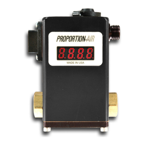
Proportion-Air ISQB1 Installation and operating instructions

1ISQB1 Installation Guide - 2/13/2015 | SSS
DESCRIPTION / IDENTIFICATION
The ISQB1 series control valve is an electronic
pressure regulator designed to precisely and
proportionally control the pressure of gaseous media
based on an electronic control signal.
The ISQB1 operates using two normally closed
solenoid valves, a pressure sensor, and a control
circuit. One valve is actuated to allow supply media
into the system. The second valve is actuated to allow
working media to vent through a threaded port to
atmosphere. The pressure sensor provides feedback
to the control circuit. The control circuit compares the
pressure sensor feedback to the user supplied
electronic command signal and actuates the
appropriate valve until the two signals match.
The ISQB1 series can be teamed with a variety of air
piloted pressure volume boosters for even greater
flow.
† Pressure ranges are customer specified. Output pressures other
than 100% are available.
ELECTRICAL
SUPPLY VOLTAGE 13.9 to 29 VDC (MAX)
SUPPLY CURRENT < 80 mA
COMMAND SIGNAL 4-20 mA Differential
COMMAND SIGNAL IMPEDANCE Current=100 Ω
MECHANICAL
PRESSURE RANGES Full Vacuum - 150 psig
(29.9 in. HG (Vac) - 10.3 Bar)
OUTPUT PRESSURE† 0-100% of range
FLOW RATE 0.80 SCFM @ 80 PSIG
(23 L/min @ 5.52 Bar)
Min CLOSED END VOLUME 1 in3
PORT SIZE 1/8” NPT
FILTRATION RECOMMENDED 20 Micron (included)
LINEARITY/HYSTERESIS <±0.15% F.S. BFSL
REPEATABILITY <±0.02% F.S.
ACCURACY <±0.2% F.S.
PHYSICAL
OPERATING TEMERPATURE 32-104°F (0-40°C) (T4)
WEIGHT 2.5 lbs. (1.1 Kg)
PROTECTION RATING NEMA 4
HOUSING Blue Anodized Aluminum
SPECIFICATIONS
HAZARDOUS AREA CLASSIFICATION
The ISQB is rated Intrinsically Safe and is
Factory Mutual approved for Class I, II &
III, Division 1, Groups C, D, E, F & G
Entity Parameters:
V Max = 29 VDC
I Max = 150 MA
Ci = 0.26uF
Li = 0
Field Wiring Drawing: ISQB-96026-2
NOTES: End user must determine fitness and
suitability of the ISQB1 control valve for their application.
The ISQB requires the use of Intrinsically Safe Barriers.
PROPORTION-AIR, INC.
8250 N. 600 West
McCordsville, IN 46055
877.331.1738
WETTED MATERIALS
PARAMTERS Port 1 (Pressure Port) Port 2 (Reference Port)
COVERS High Temperature Polyamide High Temperature Polyamide
SUBSTRATE Alumina Ceramic Alumina Ceramic
ADHESIVES Epoxy, RTV Epoxy, RTV
ELECTRONIC COMPONENTS Ceramic, Silicon Silicon, Glass, Gold, Solder
INSTALLATION & MAINTENANCE INSTRUCTIONS

2ISQB1 Installation Guide - 2/13/2015 | SSS
Electrical Connections:
1. All intrinsically safe installation must conform to
applicable Factory Mutual Code recommendations
and the National Electric Code, as well as any
applicable local codes or Fire Marshal directives. All
intrinsically safe installations must be performed by
personnel trained in the proper application of the
above.
2. Ensure all power is off before making any electrical
connections.
3. Figure 1 shows the location of the ISQB1 electrical
connector and figure 2 shows the connector. Table 2
identifies each connection
4. Must be wired in accordance with the supplied field
wiring drawing.
TABLE 2
ISQB1 PIN DESIGNATORS
PIN FUNCTION
1DC COMMON
2COMMAND (-)
3 NC
4COMMAND (+)
5NC
6POWER
Pneumatic Connections:
1. A typical 20 micron (minimum 40 micron) in-line filter
is recommended on the inlet of the ISQB1.
2. Connect supply pressure to the “IN” INLET PORT
(figure 1). See Table 1 for maximum supply
pressure.
3. Connect the “OUT” OUTLET PORT (figure 1) to the
device being controlled.
4. Media vents through exhaust port. If the media is
hazardous (classified), the threaded exhaust port
(figure 1) should be vented into a safe area.
5. Proceed with electrical connection.
TABLE 1
RATED PRESSURE FOR ISQB1 VALVES
For valves ordered with MAX.
calibrated pressure of Max. inlet pressure is
Vacuum up to 10 psig (0.69 bar) Consult factory
10.1 up to 30 psig (0.70 up to 2 bar) 35 psig (2.4 bar)
31 up to 100 psig (2.1 up to 7 bar) 110 psig (7.6 bar)
101 up to 150 psig (7 up to 12 bar) 150 psig (12 bar)
Figure 1
ZERO & SPAN
ACCESS CAP
THREADED
EXHAUST PORT
10-32 UNF
ELECTRICAL
CONNECTOR
QBT-01
BRACKET
ATMOSPHERIC
REFERENCE
INLET PORT OUTLET PORT
Figure 2
PIN 1
DC COMMON (-)
PIN 2
4-20 MA COMMAND (-)
PIN 6
DC POWER (+)
PIN 4
4-20 MA COMMAND (+)
NC
NC
Before you get started, please read these warnings:
Examine the product. Ensure that you received what you
ordered.
Read this guide first before you start and save it for later use.
All compressed air and power should be shut off before
installing, removing or performing maintenance on this product.
Installation and use of this product should be under the
supervision and control of properly qualified personnel in order
to avoid the risk of injury or death.
Media vents through exhaust port. If the media is hazardous
(classified), the exhaust port should be vented into a safe area.

3ISQB1 Installation Guide - 2/13/2015 | SSS
FIELD WIRING DRAWING ISQB-96026-2 (General Barrier)

4ISQB1 Installation Guide - 2/13/2015 | SSS
FIELD WIRING DRAWING ISQB-96026-2 (PEPPERL-FUCHS KFD2)

5ISQB1 Installation Guide - 2/13/2015 | SSS
FIELD WIRING DRAWING ISQB-96026-2 (PEPPERL-FUCHS Z728/KFD2)

6ISQB1 Installation Guide - 2/13/2015 | SSS
FIELD WIRING DRAWING ISQB-96026-2 (PHEONIX CONTACT MACX)

7ISQB1 Installation Guide - 2/13/2015 | SSS
FIELD WIRING DRAWING ISQB-96026-2 (PEPPERL-FUCHS KFD0)

8ISQB1 Installation Guide - 2/13/2015 | SSS
FIELD WIRING DRAWING ISQB-96026-2 (PEPPERL-FUCHS Z728)

9ISQB1 Installation Guide - 2/13/2015 | SSS
Example Part Number : ISQB1 T B N I X Z P 150 PS G BR
YOUR PART NUMBER : T I X
Section ——> 1 2 3 4 5 6 7 8 9 10 11 12 Options
1 Series
ISF1 Nonincindive ISF1*
ISQB1 Intrinsically Safe ISQB1
11 Pressure Unit
PS PSI Inches Hg IH
MB Millibars Inches H2OIW
BR Bar mm H2OMW
KP Kilopascal Kilograms/cm² KG
MP Megapascal Torr* TR
MH mm Hg
3 Manifold Material
B Brass (Standard)
A Aluminum
4 Thread Type
N NPT (Standard)
P BSPP
5 Input Signal Range
I 4 to 20 mADC
6 Monitor Signal Range
X No Monitor
7 Zero Offset
N 0% Pressure Starts Below Atmosphere
P 0% Pressure Starts Above Atmosphere
Z 0% Pressure Starts at Zero (Typical)
9 Full Scale Pressure Type
N 100% Pressure Ends Below Atmosphere
P 100% Pressure Ends Above Atmosphere
Z 100% Pressure Ends at Zero
10 Full Scale Pressure
Must be less than or equal to 150 psig
12 Pressure Unit of Measure
A Absolute Pressure
G Gage Pressure
8 Zero Offset Pressure
Typical is 0 (blank)*- If Greater than 30% of Full Scale
Pressure (#9 below) Please Consult Factory.
*Requires Afor Pressure Unit of Measure
*If Zfor Zero Offset (#7), please leave blank
2 Sensor Type
T -14.7 to 150 psig
13 Options
R1 Rotate Connector 180 Degrees
BR Install Foot Bracket
MOUNTING BRACKET
Type Bracket P#
Wrap-Around QBT-01
Please Note: The user has the additional
responsibility of supplying and or ensuring that the
connector/cable that is used with any Proportion-
Air ISQB or ISF1 series FM approved product,
meets all local and national codes for intrinsically
safe wiring.

10 ISQB1 Installation Guide - 2/13/2015 | SSS
5. Set the electrical command input to 20mADC. Adjust
the SPAN potentiometer until MAXIMUM desired
pressure is reached (clockwise to increase pressure).
6. Set the electrical command input to 10 percent of full
value (5.6mA).
7. Adjust the ZERO potentiometer until 10 percent of
maximum desired pressure is reached. (clockwise
increases pressure).
8. The ZERO and SPAN potentiometers interact slightly.
Repeat steps 5-10 until no error exists.
9. Verify unit shuts off by going to 4mADC command.
Check linearity by going to at least six pressures
throughout the full range.
NOTE: Only use this step if your device is totally
out of calibration. If it is slightly out of calibration,
omit this step and move on to paragraph 5. Using a
small screwdriver, turn both potentiometers 15 turns
clockwise. Then turn them 7 turns counter clockwise.
This will put the ISQB1 roughly at mid scale.
Re-calibration:
1. Wire the ISQB1 according to the section titled
“Electrical Connections.”
2. Connect a precision pressure gage or pressure
transducer to the OUTLET PORT of the ISQB1.
NOTE: There must be a closed volume of at least
1 in3 between the OUTLET PORT and the measuring
device for the ISQB1 to be stable.
3. Provide supply pressure to the INLET PORT of the
ISQB1. (See figure 1). Make sure supply pressure
does not exceed the rating for the valve. (see table 1)
All ISQB1 valves come calibrated from the factory by
trained personnel using precision calibration equipment.
The ISQB1 is a closed loop control valve using a
precision electronic pressure sensor. Typical drift is less
than 1% over the life of the product. If your ISQB1
appears to be out of calibration by more than 1%, it is not
likely to be ISQB1. Check the system for plumbing
leakage, wiring and electronic signal levels. Verify the
accuracy of your measuring equipment before re-
calibrating. If the ISQB1 valve needs re-calibration, use
the procedure described below:
RE-CALIBRATION PROCEDURE
4. Remove the zero and span plug on top of the ISQB1
to access the ZERO and SPAN adjustment
potentiometers (figure 1).
ISQB1 & BRACKET DIMENSIONS

11 ISQB1 Installation Guide - 2/13/2015 | SSS
Improper operaon could result in serious injury to persons or
loss of life!
1. PRODUCT COMPATIBILITY
Proporon-Air, Inc. products and accessories are for use in
industrial pneumac applicaons with compressed air
media. The compability of the equipment is the
responsibility of the end user. Product performance and
safety are the responsibility of the person who determined
the compability of the system. Also, this person is
responsible for connuously reviewing the suitability of the
products specied for the system, referencing the latest
catalog, installaon manual, Safety Precauons and all
materials related to the product.
2. EMERGENCY SHUTOFF
Proporon, Inc. products cannot be used as an emergency
shuto. A redundant safety system should be installed in
the system to prevent serious injury or loss of life.
3. EXPLOSIVE ATMOSPHERES
Products and equipment should not be used where
harmful, corrosive or explosive materials or gases are
present. Unless cered, Proporon-Air, Inc. products
cannot be used with ammable gases or in hazardous
environments.
4. AIR QUALITY
Clean, dry air is not required for Proporon-Air, Inc.
products. However, a 40 micron parculate lter is
recommended to prevent solid contaminaon from
entering the product.
5. TEMPERATURE
Products should be used with a media and ambient
environment inside of the specied temperature range of
32°F to 158°F. Consult factory for expanded temperature
ranges.
6. OPERATION
Only trained and cered personnel should operate
electronic and pneumac machinery and equipment.
Electronics and pneumacs are very dangerous when
handled incorrectly. All industry standard safety guidelines
should be observed.
7. SERVICE AND MAINTENANCE
Service and maintenance of machinery and equipment
should only be handled by trained and experienced
operators. Inspecon should only be performed aer
safety has been conrmed. Ensure all supply pressure has
been exhausted and residual energy (compressed gas,
springs, gravity, etc.) has been released in the enre
system prior to removing equipment for service or
maintenance.
Warning
Improper operaon could result in serious injury to persons or
damages to equipment!
1. PNEUMATIC CONNECTION
All pipes, pneumac hose and tubing should be free of all
contaminaon, debris and chips prior to installaon. Flush
pipes with compressed air to remove any loose parcles.
2. THREAD SEALANT
To prevent product contaminaon, thread tape is not
recommended. Instead, a non-migrang thread sealant is
recommended for installaon. Apply sealant a couple
threads from the end of the pipe thread to prevent
contaminaon.
3. ELECTRICAL CONNECTION
To prevent electronic damage, all electrical specicaons
should be reviewed and all electrical connecons should
be veried prior to operaon.
Cauon
Exempon from Liability
Warranty
1. Proporon-Air, Inc. is exempted from any damages
resulng from any operaons not contained within the
catalogs and/or instrucon manuals and operaons
outside the range of its product specicaons.
2. Proporon-Air, Inc. is exempted from any damage or loss
whatsoever caused by malfuncons of its products when
combined with other devices or soware.
3. Proporon-Air, Inc. and its employees shall be exempted
from any damage or loss resulng from earthquakes, re,
third person acons, accidents, intenonal or
unintenonal operator error, product misapplicaon or
irregular operang condions.
4. Proporon-Air, Inc. and its employees shall be exempted
from any damage or loss, either direct or indirect,
including consequenal damage or loss, claims,
proceedings, demands, costs, expenses, judgments,
awards, loss of prots or loss of chance and any other
liability whatsoever including legal expenses and costs,
which may be suered or incurred, whether in tort
(including negligence), contract, breach of statutory duty,
equity or otherwise.
Proporon-Air, Inc. products are warranted to the original
purchaser only against defects in material or workmanship for
one (1) year from the date of manufacture. The extent of
Proporon-Air’s liability under this warranty is limited to repair
or replacement of the defecve unit at Proporon-Air’s opon.
Proporon-Air shall have no liability under this warranty where
improper installaon or ltraon occurred.
Safety Precauons
Please read all of the following Safety Precauons before installing or operang any Proporon-Air, Inc. equipment or accessories.
To conrm safety, be sure to observe ‘ISO 4414: Pneumac Fluid Power - General rules relang to systems’ and other safety
pracces.
Table of contents
Other Proportion-Air Controllers manuals
Popular Controllers manuals by other brands
ARI
ARI ARI-PACO 2G Operating and installation instructions

Sulion
Sulion Driver VISIO IoT manual

Chemitech IT Perdana
Chemitech IT Perdana pH/ORP-3500 Series Operation manual

Crestron
Crestron 302 installation guide
Bollfilter
Bollfilter 2200 Operating and installation instructions
Rockwell Automation
Rockwell Automation Allen-Bradley MicroLogix 1400 user manual
