DATREND Systems venTest User manual

Operating Manual
venTest™
Ventilator Tester
MN-108


To order this manual, use Part Number 6100-200
Revision
Revision History
Description Date
A Initial Release 2016-Mar-08
B General update 2018-Jun-28
Copyright
Datrend Systems Inc. (“DSI”) agrees to a limited copyright release that allows you to reproduce manuals and other
printed materials for use in service training programs and other technical publications. If you would like other
reproductions or distributions, submit a written request to Datrend Systems Inc.
Unpacking and Inspection
Follow standard receiving practices upon receipt of the instrument. Check the shipping carton for damage. If damage
is found, stop unpacking the instrument. Notify the freight carrier and ask for an agent to be present while the instrument
is unpacked. There are no special unpacking instructions, but be careful not to damage the instrument when unpacking
it. Inspect the instrument for physical damage such as bent or broken parts, dents, or scratches.
Claims
Our routine method of shipment is via common carrier. Upon delivery, if physical damage is found, retain all packing
materials in their original condition and contact the carrier immediately to file a claim.
If the instrument is delivered in good physical condition but does not operate within specifications, or if there are any
other problems not caused by shipping damage, please contact your local sales representative or DSI immediately.
Standard Terms and Conditions
Refunds & Credits
Please note only serialized products (products labelled with a distinct serial number) and accessories are eligible for
partial refund and/or credit. Non-serialized parts and accessory items (cables, carrying cases, auxiliary modules, etc.)
are not eligible for return or refund. In order to receive a partial refund/credit, the product must not have been damaged,
and must be returned complete (meaning all manuals, cables, accessories, etc.) within 90 days of original purchase and
in “as new” and resalable condition. The Return Procedure must be followed.
Return Procedure
Every product returned for refund/credit must be accompanied by a Return Material Authorization (RMA) number,
obtained from Datrend Customer Service. All items being returned must be sent prepaid (freight, duty, brokerage, and
taxes ) to our factory location.
Restocking Charges
Products returned within 30 days of original purchase are subject to a minimum restocking fee of 15%. Products returned
in excess of 30 days after purchase, but prior to 90 days, are subject to a minimum restocking fee of 20%. Additional
charges for damage and/or missing parts and accessories will be applied to all returns. Products which are not in “as
new” and resalable condition, are not eligible for credit return and will be returned to the customer at their expense.
Certification
This instrument was thoroughly tested and inspected and found to meet DSI’s manufacturing specifications when it was
shipped from the factory. Calibration measurements are traceable to the National Research Council of Canada (NRC)
and/or the National Institute of Standards and Technology (NIST). Devices for which there are no NRC/NIST calibration
standards are measured against in-house performance standards using accepted test procedures.
Page i

Warranty
Warranty and Product Support
Datrend Systems Inc. ("DSI") warrants the venTest Unit (the "Datrend product") to be free from defects in materials and
workmanship under normal use and service for one (1) year from the date of original purchase. During the warranty
period DSI will, at our option, either repair or replace defects in materials and workmanship at no charge; provided the
Datrend product is returned (shipping, duty, brokerage and taxes prepaid) to DSI. Any and all transportation charges
incurred are the responsibility of the purchaser and are not included within this warranty. This warranty extends only to
the original purchaser and does not cover damage from abuse, neglect, accident or misuse or as the result of service
or modification by other than DSI. IN NO EVENT SHALL DATREND SYSTEMS INC. BE LIABLE FOR
CONSEQUENTIAL DAMAGES.
This warranty is subject to the following limitations:
!Standard Accessories: 90 day limited warranty
!Re-calibration of the instrument, which has a recommended annual calibration frequency, is not covered under the
warranty.
No warranty shall apply when damage is caused by any of the following:
!Power failure, surges, or spikes,
!Damage in transit, when moving the instrument, or if the unit is dropped,
!Improper power supply such as low voltage, incorrect voltage, defective wiring or inadequate fuses,
!Accident, alteration, abuse or misuse of the instrument,
!Fire, water damage, theft, war, riot, hostility, acts of God, such as hurricanes, floods, etc.
Only serialized products (those items bearing a distinct serial number tag) and their accessory items are covered under
this warranty. PHYSICAL DAMAGE CAUSED BY MISUSE OR PHYSICAL ABUSE IS NOT COVERED UNDER THE
WARRANTY. Items such as cables and non-serialized modules are not covered under this warranty.
This warranty gives you specific legal rights and you may have other rights, which vary from province to province, state
to state, or country to country. This warranty is limited to repairing the instrument to DSI's specifications.
When you return an instrument to DSI for service, repair or calibration, we recommend shipment using the original
shipping foam and container. If the original packing materials are not available, we recommend the following guide for
repackaging:
!Use a double-walled carton of sufficient strength for the weight being shipped.
!Use heavy paper or cardboard to protect all instrument surfaces. Use non-abrasive material around all projecting parts.
!Use at least four inches of tightly packed, industrial-approved, shock-absorbent material all around the instrument.
DSI will not be responsible for lost shipments or instruments received in damaged condition due to improper packaging
or handling. All warranty claim shipments must be made on a prepaid basis (freight, duty, brokerage, and taxes). No
returns will be accepted without a Return Materials Authorization ("RMA”) number. Please contact to obtain an RMA
number and receive help with shipping/customs documentation.
Page ii

Warranty Disclaimer
Should you elect to have your instrument serviced and/or calibrated by someone other than Datrend Systems or an
Authorized Service Centre, please be advised that the original warranty covering your product becomes void when the
tamper-resistant Quality Seal is removed or broken without proper factory authorization. We strongly recommend,
therefore, that you send your instrument to Datrend Systems or an Authorized Service Centre for service and calibration,
especially during the original warranty period.
In all cases, breaking the tamper-resistant Quality Seal should be avoided at all cost, as this seal is the key to your
original instrument warranty. In the event that the seal must be broken to gain internal access to the instrument (e.g.,
in the case of a customer-installed firmware upgrade), you must first contact Datrend Systems at 1-604-291-7747. You
will be required to provide us with the serial number for your instrument as well as a valid reason for breaking the Quality
Seal. You should break this seal only after you have received factory authorization. Do not break the Quality Seal before
you have contacted us! Following these steps will help ensure that you will retain the original warranty on your instrument
without interruption.
WARNING
Unauthorized user modifications or application beyond the published specifications may result in electrical shock hazards
or improper operation. Datrend Systems will not be responsible for any injuries sustained due to unauthorized equipment
modifications.
DSI DISCLAIMS ALL OTHER WARRANTIES, EXPRESSED OR IMPLIED, INCLUDING ANY WARRANTY OF
MERCHANTABILITY OR FITNESS FOR A PARTICULAR PURPOSE OR APPLICATION.
THIS PRODUCT CONTAINS NO USER-SERVICEABLE COMPONENTS.
UNAUTHORIZED REMOVAL OF THE INSTRUMENT COVER SHALL VOID
THIS AND ALL OTHER EXPRESSED OR IMPLIED WARRANTIES.
Note: Calibration of Datrend products typically involves adjustment of parameters stored in firmware by proprietary
software. Parties other than Datrend and its Authorized Service Centers are limited to verification of the status of the
accuracy of the instrument. Do not confuse verification with calibration.
Page iii

Page iv

venTest OPERATORS MANUAL
Table of Contents
ABBREVIATIONS AND DEFINITIONS.....................................VIII
SYMBOL DEFINITIONS............................................... X
1 SPECIFICATIONS................................................. 1
1.1 Instrument Specifications.. . . . . . . . . . . . . . . . . . . . . . . . . . . . . . . . . . . . . . . . . . 1
1.1.1 FlowSense 300 (Hi Flow) Sensor Measurement .. . . . . . . . . . . . . . . . . 1
1.1.2 FlowSense 012 (Low Flow) Sensor Measurement . . . . . . . . . . . . . . . . 4
2
1.1.3 Oxygen (O ) Sensor Measurement .. . . . . . . . . . . . . . . . . . . . . . . . . . . 7
1.1.4 IRMA AX+ Multigas Sensor. . . . . . . . . . . . . . . . . . . . . . . . . . . . . . . . 8
TM
1.2 UserInterface. .................................................. 9
1.3 ElectricalRatings................................................. 9
1.4 EnvironmentforUse. ............................................. 9
1.5 Dimensions. ................................................... 10
1.6 Weight........................................................ 10
1.7 StandardAccessories. ........................................... 10
1.8 OptionalAccessories............................................. 10
1.9 Compliance With Standards. . . . . . . . . . . . . . . . . . . . . . . . . . . . . . . . . . . . . . . 10
2 OVERVIEW.................................................... 11
2.1 Features. ..................................................... 12
2.1.1 Analyzer Base Unit. . . . . . . . . . . . . . . . . . . . . . . . . . . . . . . . . . . . . . . 12
2.1.2 Pressure Connections. . . . . . . . . . . . . . . . . . . . . . . . . . . . . . . . . . . . . 14
2.1.3 Flow Sensor Connection. . . . . . . . . . . . . . . . . . . . . . . . . . . . . . . . . . . 14
2.1.4 Oxygen Sensor Connection.. . . . . . . . . . . . . . . . . . . . . . . . . . . . . . . . 16
2.1.5 IRMA Sensor Connection. . . . . . . . . . . . . . . . . . . . . . . . . . . . . . . . . 16
TM
2.1.6 Ethernet. .............................................. 17
2.1.7 USB................................................... 17
2.1.8 SDCardslot............................................ 17
2.1.9 Reset.................................................. 17
3 GENERAL INSTRUCTIONS.......................................... 18
3.1 Safety. ....................................................... 18
3.1.1 Responsibility of Operating Staff. . . . . . . . . . . . . . . . . . . . . . . . . . . . . 18
3.2 Maintenance. .................................................. 19
3.3 Manufacturer Liability.. . . . . . . . . . . . . . . . . . . . . . . . . . . . . . . . . . . . . . . . . . . . 19
3.4 Precautions.................................................... 20
3.5 IntendedUse................................................... 21
4 OPERATION. .................................................. 22
4.1 Power. ....................................................... 22
4.1.1 PowerON.............................................. 23
Table of Contents #Page v

venTest OPERATORS MANUAL
4.1.2 Power OFF/Power Button Menu. . . . . . . . . . . . . . . . . . . . . . . . . . . . . 23
4.1.3 Energy Saving Mode. . . . . . . . . . . . . . . . . . . . . . . . . . . . . . . . . . . . . . 24
4.1.4 Screenshots. ........................................... 24
4.2 UserInterface. ................................................. 25
4.2.1 Keyboard............................................... 26
4.2.2 Swipescreens........................................... 27
4.2.3 TraceDisplay. .......................................... 28
4.2.4 Measured Value Display. . . . . . . . . . . . . . . . . . . . . . . . . . . . . . . . . . . 29
4.2.5 MainDisplay............................................ 30
4.3 StatusBar..................................................... 31
4.4 Structure of Measured Values Display. . . . . . . . . . . . . . . . . . . . . . . . . . . . . . . . 33
4.4.1 Measured Value Configuration Menu. . . . . . . . . . . . . . . . . . . . . . . . . 33
4.5 Overview: Measured Value. . . . . . . . . . . . . . . . . . . . . . . . . . . . . . . . . . . . . . . . 36
4.5.1 Flow Measured Values. . . . . . . . . . . . . . . . . . . . . . . . . . . . . . . . . . . . 36
4.5.2 Ventilation Values. . . . . . . . . . . . . . . . . . . . . . . . . . . . . . . . . . . . . . . . 36
4.5.3 Pressure Measured Values. . . . . . . . . . . . . . . . . . . . . . . . . . . . . . . . . 37
4.5.4 Gas Concentration Values.. . . . . . . . . . . . . . . . . . . . . . . . . . . . . . . . . 38
4.5.5 Other.................................................. 38
4.6 Overview: Standard Conditions. . . . . . . . . . . . . . . . . . . . . . . . . . . . . . . . . . . . . 39
4.7 Filter. ........................................................ 40
4.8 FlowSense Settings Button. . . . . . . . . . . . . . . . . . . . . . . . . . . . . . . . . . . . . . . . 40
4.9 Graph Configuration Menu.. . . . . . . . . . . . . . . . . . . . . . . . . . . . . . . . . . . . . . . . 41
4.10 MainMenu.................................................... 42
4.10.1 SetupSubMenu........................................ 43
4.10.1.1 InfoandUpdate.......................................... 44
4.10.1.2 Date, Sound and Language. . . . . . . . . . . . . . . . . . . . . . . . . . . . . . . . . 45
4.10.1.3 Network................................................ 46
4.10.1.4 Service................................................. 48
4.10.2 Display Sets Sub Menu. . . . . . . . . . . . . . . . . . . . . . . . . . . . . . . . . . . 49
4.10.3 Selection of Display Sets.. . . . . . . . . . . . . . . . . . . . . . . . . . . . . . . . . 50
4.10.4 Creation of New Display Sets. . . . . . . . . . . . . . . . . . . . . . . . . . . . . . 51
4.10.5 Modifying Existing Display Sets.. . . . . . . . . . . . . . . . . . . . . . . . . . . . 51
4.10.6 Import / Export of Display Sets. . . . . . . . . . . . . . . . . . . . . . . . . . . . . 52
4.10.7 Deleting Display Sets. . . . . . . . . . . . . . . . . . . . . . . . . . . . . . . . . . . . 52
4.11 ‘Logging’SubMenu............................................. 53
4.12 SensorsSubMenu. ............................................ 56
4.12.1 Zeroing of Pressure Sensors.. . . . . . . . . . . . . . . . . . . . . . . . . . . . . . 57
4.12.2 FlowSense Hi and Lo Sensors. . . . . . . . . . . . . . . . . . . . . . . . . . . . . 58
4.12.2.1 'General'............................................... 59
4.12.2.2 Inspiration & Expiration Trigger . . . . . . . . . . . . . . . . . . . . . . . . . . . . . 60
4.12.2.3 'Adjustment' Button. . . . . . . . . . . . . . . . . . . . . . . . . . . . . . . . . . . . . . 63
2
4.12.3 O-Sensor............................................. 65
4.12.4 IRMA™AX+........................................... 67
4.13 Creating Test Procedures and Test Reports (optional). . . . . . . . . . . . . . . . . . 68
4.14 SensorStartup................................................. 69
4.14.1 FlowSense Airflow Sensor.. . . . . . . . . . . . . . . . . . . . . . . . . . . . . . . . 69
Table of Contents #Page vi

venTest OPERATORS MANUAL
2
4.14.2 O -Sensor (optional). . . . . . . . . . . . . . . . . . . . . . . . . . . . . . . . . . . . . 70
4.14.3 IRMA™AX+........................................... 70
4.15 Troubleshooting & Error Handling. . . . . . . . . . . . . . . . . . . . . . . . . . . . . . . . . . 70
4.15.1 BiFlow-Sensor Error Messages. . . . . . . . . . . . . . . . . . . . . . . . . . . . . 70
4.15.2 IRMA™ AX+ Sensor Error Messages. . . . . . . . . . . . . . . . . . . . . . . . 71
4.16 Cleaning. .................................................... 72
4.16.1 Housing.............................................. 72
4.16.2 Display............................................... 72
4.16.3 FlowSense Sensor. . . . . . . . . . . . . . . . . . . . . . . . . . . . . . . . . . . . . . 72
4.17 Maintenance and Calibration. . . . . . . . . . . . . . . . . . . . . . . . . . . . . . . . . . . . . . 73
4.17.1 venTest. ............................................. 73
4.17.2 Oxygensensor......................................... 73
4.17.3 Waste Management. . . . . . . . . . . . . . . . . . . . . . . . . . . . . . . . . . . . . 75
4.17.4 Technical Support. . . . . . . . . . . . . . . . . . . . . . . . . . . . . . . . . . . . . . 76
APPENDIX A: TRIGGERING OPTIONS.................................... 77
1 Trigger Options of venTest. . . . . . . . . . . . . . . . . . . . . . . . . . . . . . . . . . . . . . . . . 77
2 Volume measuring of Gases.. . . . . . . . . . . . . . . . . . . . . . . . . . . . . . . . . . . . . . . 80
3 Consequences of Physical Characteristics Of a Gas . . . . . . . . . . . . . . . . . . . . . 83
APPENDIX B: UNDERSTANDING DATA RECORDS........................... 87
1 Recording Data from a Test. . . . . . . . . . . . . . . . . . . . . . . . . . . . . . . . . . . . . . . . 87
APPENDIX C: CONNECTING TO A WINDOWS DATA SHARE. ................... 91
1 General........................................................ 91
2 WorkgrouporDomain?............................................ 93
3 Connecting to a Workgroup Share. . . . . . . . . . . . . . . . . . . . . . . . . . . . . . . . . . . 93
4 Connecting to a Domain Share. . . . . . . . . . . . . . . . . . . . . . . . . . . . . . . . . . . . . . 99
Table of Contents #Page vii

venTest OPERATORS MANUAL
Abbreviations and Definitions
The following abbreviations, terms and acronyms are used throughout this manual:
ENF enflurane
DES desflurane
HAL halothane
ISO isoflurane
SEV sevoflurane
lliter
ml milliliter
l/min liters per minute
ml/min milliliters per minute
l/s liters per second
cfm cubic feet per minute
s, sec second
ms, msec millisecond
kPa kilopascal
hPa hectopascal
MPa megapascal
2
cmH O centimeters of water
psi pounds-force per square inch
bar bar
mbar millibar
%percent
mmHg millimeters of mercury
Torr Torr
2
inH O inches of water
inHg inches of mercury
F
odegrees Fahrenheit
C
odegrees Celcius
Definitions #Page viii

venTest OPERATORS MANUAL
Hz Hertz
1/min 1 per minute
% Vol Volume percent
% r.f. Percent relative humidity
% h Percent per hour
mAh milliamp-hours
Definitions #Page ix
venTest OPERATORS MANUAL
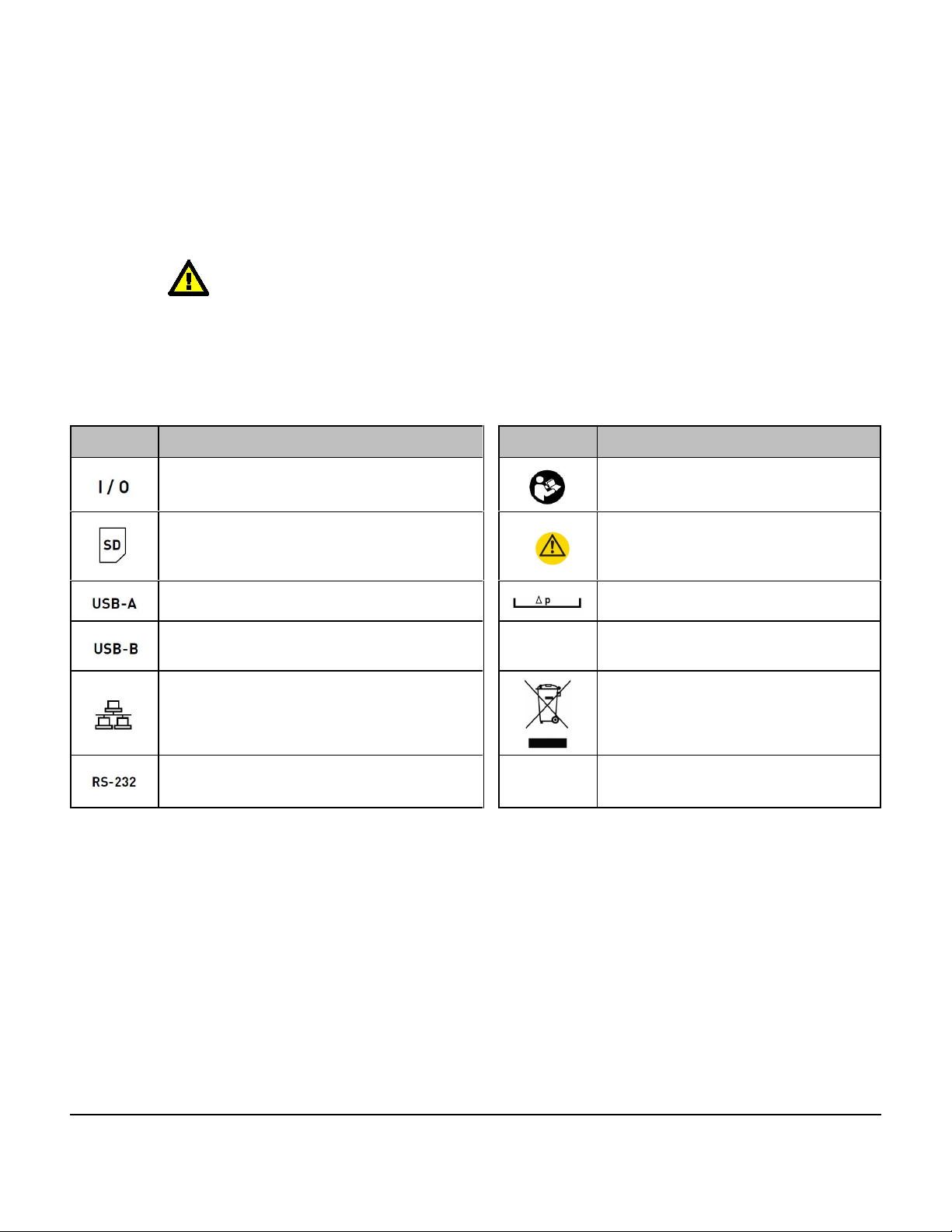
Symbol Definitions
The following symbols may be found on venTest:
CONSULT MANUAL FOR PROPER OPERATION
The operating manual provides valuable information on the proper use of venTest. It is highly recommended the operator
read the instructions thoroughly before operating the device. It is possible to damage the Equipment and/or cause harm
to the operator if venTest is used incorrectly.
The following symbols may appear on the device or in the manual.
Symbol Description Symbol Description
ON/OFF Button Read Instruction Manual
SD Memory Card Warning
USB Type A, Host port Differential Pressure
USB Type B, Device Port LAttention/Information
Ethernet Port Note on waste disposal
DB9 Female, serial port
(*special purpose)
Definitions #Page x

venTest OPERATORS MANUAL
1 Specifications
Performance Specifications
1.1 Instrument Specifications
1.1.1 FlowSense 300 (Hi Flow) Sensor Measurement
Physical Data
Dimensions 150 mm x 41 mm x 58 mm (L x W x H)
Connector 1 Cone ID 22 mm
Connector 2 Cone OD 22 mm, ID 15 mm
Weight Approx. 290 g
Environmental Conditions
Parameter Operation Storage
Temperature 10 to 40 EC -20 to 50 EC
Ambient Humidity 5 to 95% RH
(non-condensing)
5 to 95% RH (non-condensing)
Gas Temperature 10 to 40 EC
Gas Humidity 0 to 95% RH
(non-condensing)
Ambient Pressure 60 - 110 kPa 60 - 110 kPa
Specifications/Chapter 1 #Page 1

venTest OPERATORS MANUAL
Range and Accuracy
Parameter Units Range
Accuracy
(whichever is
greater)
Flow: Air ± 300 l/min ± 2% or 0.1 l/min
(STPD)
2
Flow: O ± 200 l/min ± 4% or 0.2 l/min
(STPD)
2
Flow: Air/O ± 200 l/min ± 4% or 0.2 l/min
(STPD)
Vti l; ml 0 - 10 L ± 2% of m.v. or 0.2 l
(AIR) **
± 4% of m.v. or 0.4 l
2 2
(O , AIR/O ) **
Vte l; ml 0 - 10 L ± 2% of m.v. or 0.2 l
(AIR) **
± 4% of m.v. or 0.4 l
2 2
(O , AIR/O ) **
MVi l/min; ml/min 0.5 - 50 L/min (AIR)
2
0.5 - 50 L/min (O ,
2
AIR/O )
± 2% of m.v. or 0.2
l/min (AIR) **
± 4% of m.v. or 0.4
2 2
l/min (O , AIR/O ) **
MVe l/min; ml/min 0.5 - 50 L/min (AIR)
2
0.5 - 50 L/min (O ,
2
AIR/O )
± 2% of m.v. or 0.2
l/min (AIR) **
± 4% of m.v. or 0.4
2 2
l/min (O , AIR/O ) **
Breath Rate (Freq) BrPM 1 - 100 BrPM
101 - 200 BrPM
± 0.1 BrPM ‡
± 0.2 BrPM ‡
2
Ventilation Pressure kpa; mbar; cmH O;
mmHg; psi; hpa
0 - 10 kPa ± 1% of m.v. or
0.2 hPa
2
PEEP kpa; mbar; cmH O;
mmHg; psi; hpa
0 - 10 kPa ± 1% or 0.02 kPa* **
Peak 2
kpa; mbar; cmH O;
mmHg; psi; hpa
0 - 10 kPa ± 1% or 0.02 kPa* **
Specifications/Chapter 1 #Page 2

venTest OPERATORS MANUAL
Range and Accuracy
Parameter Units Range
Accuracy
(whichever is
greater)
Plateau 2
kpa; mbar; cmH O;
mmHg; psi; hpa
0 - 10 kPa ± 1% or 0.02 kPa* **
2
Mean kpa; mbar; cmH O;
mmHg; psi; hpa
0 - 10 kPa ± 1% or 0.02 kPa* **
I/E 300/1 - 1/300 ± 0.1 **
Ti s; ms 0 - 60 sec ± 1% ± 0.02sec **
Te s; ms 0 - 60 sec ± 1% ± 0.02sec **
Tip s; ms 0 - 60 sec ± 1% ± 0.02sec **
Tep s; ms 0 - 60 sec ± 1% ± 0.02sec **
Humidity % rh 5 - 95% 5 - 80 % rh: ± 3%
80 - 95 % rh: ± 4%
Insp. Peak Flow l/min; ml/min 0 - 300 L/min (AIR)
2
0 - 200 L/min (O ,
2
AIR/O
± 2% of m.v. or 0.1
l/min (AIR) **
± 4% of m.v. or 0.2
2 2
l/min (O , AIR/O ) **
Exp. Peak Flow l/min; ml/min 0 - 300 L/min (AIR)
2
0 - 200 L/min (O ,
2
AIR/O
± 2% of m.v. or 0.1
l/min (AIR) **
± 4% of m.v. or 0.2
2 2
l/min (O , AIR/O ) **
2
HFO Pmean kpa; mbar; cmH O;
mmHg; psi; hpa
0 - 10 kPa ± 2% of m.v. or 0.04
kPa* **
2
HFO PMax kpa; mbar; cmH O;
mmHg; psi; hpa
0 - 10 kPa ± 2% of m.v. or 0.04
kPa* **
2
HFO PMin kpa; mbar; cmH O;
mmHg; psi; hpa
0 - 10 kPa ± 2% of m.v. or 0.04
kPa* **
2
HFO amplitude kpa; mbar; cmH O;
mmHg; psi; hpa
0 - 10 kPa ± 2% of m.v. or 0.04
kPa* **
HFO frequency Hz 0 - 20 ± 1 Hz
HFO I/E 3/1 - 1/3 ± 0.3
(*) Please note that due to the pneumatic resistance of the Flowsense 300 Sensor the measured pressure from the ventilation pressure sensor may differ from values
measured at other places in breathing system, especially at high flows .
(**) Subject to trigger settings
Specifications/Chapter 1 #Page 3

venTest OPERATORS MANUAL
1.1.2 FlowSense 012 (Low Flow) Sensor Measurement
Physical Data
Dimensions 125 mm x 41 mm x 58 mm (L x W x H)
Connector 1 6 mm tube connection
Connector 2 6 mm tube connection
Weight Approx. 290 g
Environmental Conditions
Parameter Operation Storage
Temperature 10 to 40 EC -20 to 50 EC
Ambient Humidity 5 to 95% RH
(non-condensing) 5 to 95% RH (non-condensing)
Gas Temperature 10 to 40 EC
Gas Humidity 0 to 95% RH
(non-condensing)
Ambient Pressure 60 - 110 kPa 60 - 110 kPa
Range and Accuracy
Parameter Units Range
Accuracy
(whichever is
greater)
Flow: Air ± 12 l/min ± 2% or 0.01 l/min
(STPD)
2
Flow: O ± 12 l/min ± 4% or 0.02 l/min
(STPD)
2
Flow: Air/O ± 12 l/min ± 4% or 0.02 l/min
(STPD)
Vti l; ml 0 - 7.5 L ± 2% of m.v. or 20 ml
(AIR) ‡
Vte l; ml 0 - 7.5 L ± 2% of m.v. or 20 ml
(AIR) ‡
Specifications/Chapter 1 #Page 4

venTest OPERATORS MANUAL
Range and Accuracy
Parameter Units Range
Accuracy
(whichever is
greater)
MVi l/min; ml/min 0.5 - 12 L/min (AIR)
2
0.5 - 12 L/min (O ,
2
AIR/O )
± 2% of m.v. or 20
ml/min (AIR) ‡
± 4% of m.v. or 40
2 2
ml/min (O , AIR/O ) ‡
MVe l/min; ml/min 0.5 - 12 L/min (AIR)
2
0.5 - 12 L/min (O ,
2
AIR/O )
± 2% of m.v. or 0.2
l/min (AIR) ‡
± 4% of m.v. or 0.4
2 2
l/min (O , AIR/O ) ‡
Breath Rate (Freq) BrPM 1 - 100 BrPM
101 - 200 BrPM
± 0.1 BrPM ‡
± 0.2 BrPM ‡
Ventilation Pressure kpa; Mpa; bar; mbar;
2
cmH O; mmHg; psi;
2
hpa; Torr; inH O; inHg
0 - 10 kPa ± 1% of m.v. or
0.2 hPa
2
PEEP kpa; mbar; cmH O;
mmHg; psi; hpa
0 - 10 kPa ± 1% or 0.02 kPa
† ‡
2
Peak kpa; mbar; cmH O;
mmHg; psi; hpa
0 - 10 kPa ± 1% or 0.02 kPa
† ‡
2
Plateau kpa; mbar; cmH O;
mmHg; psi; hpa
0 - 10 kPa ± 1% or 0.02 kPa
† ‡
2
Mean kpa; mbar; cmH O;
mmHg; psi; hpa
0 - 10 kPa ± 1% or 0.02 kPa
† ‡
I/E 300/1 - 1/300 ± 0.1 ‡
Ti s; ms 0 - 60 sec ± 1% ± 0.02sec ‡
Te s; ms 0 - 60 sec ± 1% ± 0.02sec ‡
Tip s; ms 0 - 60 sec ± 1% ± 0.02sec ‡
Tep s; ms 0 - 60 sec ± 1% ± 0.02sec ‡
Humidity % rh 5 - 95% 5 - 80 % rh: ± 3%
80 - 95 % rh: ± 4%
Specifications/Chapter 1 #Page 5

venTest OPERATORS MANUAL
Range and Accuracy
Parameter Units Range Accuracy
(whichever is
greater)
Insp. Peak Flow l/min; ml/min 0 - 300 L/min (AIR)
2
0 - 200 L/min (O ,
2
AIR/O
± 2% of m.v. or 0.1
l/min (AIR) ‡
± 4% of m.v. or 0.2
2 2
l/min (O , AIR/O ) ‡
Exp. Peak Flow l/min; ml/min 0 - 300 L/min (AIR)
2
0 - 200 L/min (O ,
2
AIR/O
± 2% of m.v. or 0.1
l/min (AIR) ‡
± 4% of m.v. or 0.2
2 2
l/min (O , AIR/O ) ‡
2
HFO Pmean kpa; mbar; cmH O;
mmHg; psi; hpa
0 - 10 kPa ± 2% of m.v. or
0.04 kPa
† ‡
2
HFO PMax kpa; mbar; cmH O;
mmHg; psi; hpa
0 - 10 kPa ± 2% of m.v. or
0.04 kPa
† ‡
2
HFO PMin kpa; mbar; cmH O;
mmHg; psi; hpa
0 - 10 kPa ± 2% of m.v. or
0.04 kPa
† ‡
2
HFO amplitude kpa; mbar; cmH O;
mmHg; psi; hpa
0 - 10 kPa ± 2% of m.v. or 0.04
kPa
† ‡
HFO frequency Hz 0 - 20 ± 1 Hz
HFO I/E 3/1 - 1/3 ± 0.3
(†) Please note that due to the pneumatic resistance of the Flowsense 012 Sensor the measured pressure from the ventilation pressure sensor may
differ from values measured at other places in breathing system, especially at high flows .
(‡) Subject to trigger settings
Specifications/Chapter 1 #Page 6
Table of contents
Other DATREND Systems Test Equipment manuals


