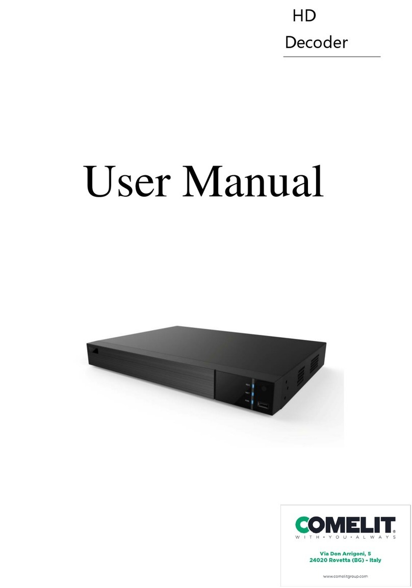
Provision ISR Ossia VMS DEC-0104 User manual

Ossia VMS-5000
DEC-0104(1U) Ossia VMS Decoder

Ossia VMS Enterprise User Manual
Contents
1Introduction ...................................................................................................................................................................1
1.1 Summary....................................................................................................................................................................1
1.2 Software Architecture ................................................................................................................................................1
1.3 System Components...................................................................................................................................................1
1.3.1 System.............................................................................................................................................................1
1.3.2 System Role....................................................................................................................................................2
2Hardware installation: ..................................................................................................................................................2
2.1 DEC-0104(1U) HW Installation: ...............................................................................................................................2
3Web-Client Connection.................................................................................................................................................2
3.1 System Settings:.........................................................................................................................................................3
3.1.1 Basic Settings..................................................................................................................................................3
3.1.2 Display............................................................................................................................................................3
3.1.3 Time................................................................................................................................................................4
3.1.4 Network Config ..............................................................................................................................................4
3.1.5 User.................................................................................................................................................................4
3.1.6 Backup............................................................................................................................................................4
3.1.7 Alarm..............................................................................................................................................................4
3.2 System Settings:.........................................................................................................................................................5
3.2.1 Upgrade...........................................................................................................................................................5
3.2.2 Reboot.............................................................................................................................................................5
3.2.3 Reset ...............................................................................................................................................................5
3.2.4 Affiliation (Device mode only).......................................................................................................................5
4Standalone Mode ...........................................................................................................................................................6
4.1 Video Settings............................................................................................................................................................6
4.1.1 Video...............................................................................................................................................................6
4.1.1 Video Group ...................................................................................................................................................7
4.2 Decoding Settings ......................................................................................................................................................7
4.2.1 Output.............................................................................................................................................................7
4.2.1 Plan (Main Interface)......................................................................................................................................8
5Configuring a Decoder on the Management Server ...................................................................................................9
5.1 Add a DEC-0104(1U) Decoder..................................................................................................................................9
5.2 Bind a DEC-0104(1U) Decoder to a TV Wall.........................................................................................................10

Ossia VMS Enterprise User Manual
1
1.1 Summary
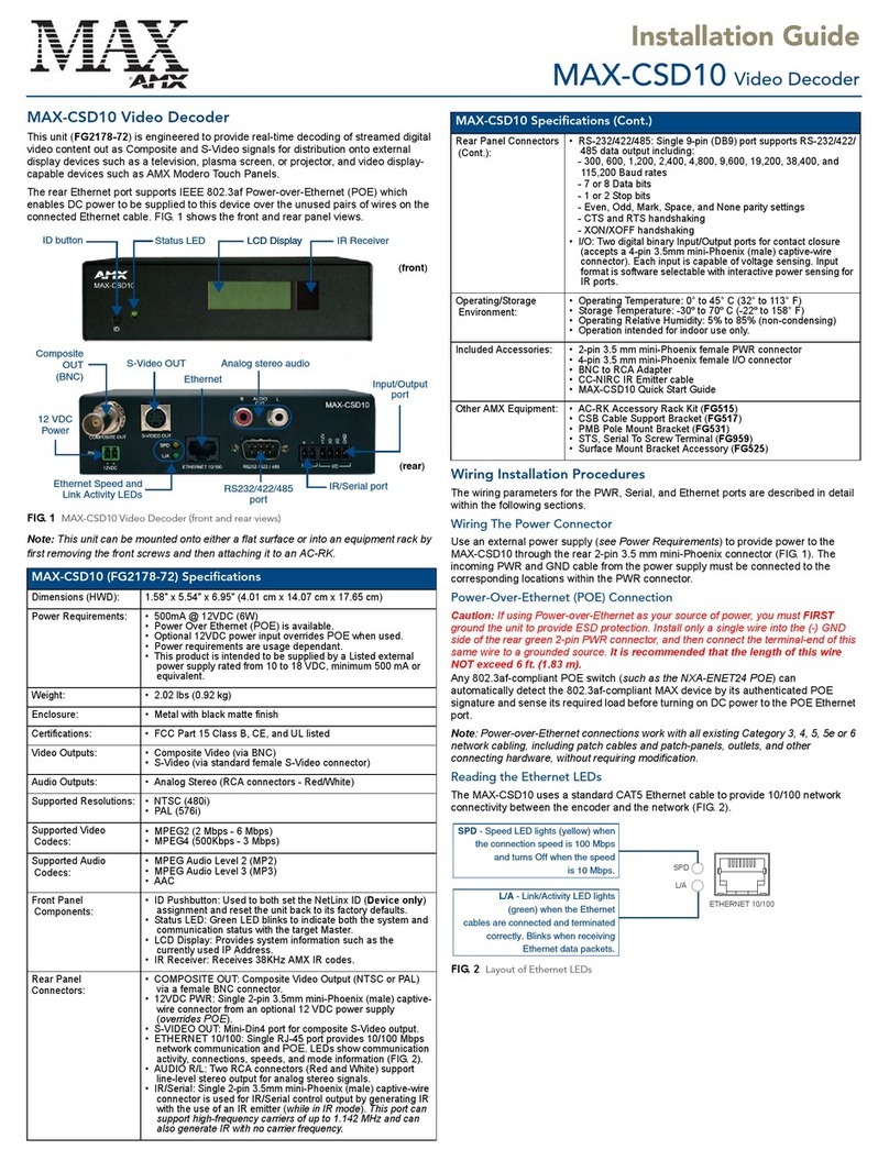
DEC-0104(1U) decoder is a part of the Ossia VMS system but can also work as a standalone decoder.
When connected to Ossia VMS server it can perform live view, playback and alarm pop up tasks.
When working as standalone it can only perform live view tasks.
1.2 Software Architecture
1.3 System Components
1.3.1 System
1 Introduction
Application Layer
Business Layer
Platform Layer
Access Layer
C/S Client B/S Client
Mobile Phone
Client
The Third
Party System
Decode to
TV Wall
Record
Storage
Record
Playback
E-Map
Alarm
Linkage
Voice
Talk
Authentication
Server
Configuration
Management
Center
Media
Transfer
Server
Monitor
Client
IPC NVR
TVI-DVR
AHD-DVR Analog
DVR
Decoder

Ossia VMS Enterprise User Manual
2
1.3.2 System Role
The decoder role is quite simple: to decode and display video from the source device on the required screen and window.
When connected through the Ossia VMS platform, the control over the decoder is done via the Ossia VMS client.
When connected as a standalone device, the control over the decoder is done via its web-client
2 Hardware installation:
The Ossia VMS HW servers are extremely simple to install. As easy as plug and play. If you are still not sure how to install it properly,
please follow the quick guide below:
2.1 DEC-0104(1U) HW Installation:
The DEC-0104(1U) is designed to be installed inside a network rack. Install it properly before connecting the required cables and connectors
as illustrated below.
1) Connect the device to and AC power outlet.
2) Connect 1-2 network cables as required
3) Connect video cables (HDMI Out/HDMI In/VGA/CVBS)
4) Turn on the device
3 Web-Client Connection
Configuring and controlling the decoder (under standalone mode) is done via the web-client. It supports IE9/IE10/IE1. In order to install
firmware updates, Please make sure that your browser
supports the downloading and use of the Web Client. (Only
Latest IE, and old versions of Firefox and Chrome).
❖Login
By default, the decoder will get an IP address by DHCP and
port will be 80. It can be found by Provision-ISR’s IP
manager tool. (Device type will show “Decoder”). For
example, http://192.168.50.3/. Then input the user name and
password (default is: admin/123456), select the language and
then click “Login” to log in to the IE client.
Please note:
1. The DEC-0104(1U) decoder doesn’t have a local UI. Nothing will appear on the monitors after installation and bootup
2. HDMI 1+3 support 4K/1080P/1280x1024. HDMI 2+4 support 1080P/1280x1024

Ossia VMS Enterprise User Manual
3
3.1 System Settings:
3.1.1 Basic Settings
Running Mode: The main configuration is the “Running
mode” which will actually set if the decoder is working as
part of a VMS system or it is a standalone device
controlled by the web-client. By default, the “Running
Mode” is set to “Platform” which is the Ossia VMS
platform. If you need to change it, you can change to
“Device” which is standalone operation. The features will
be slightly different based on each choice.
User Permission: By default, the permission is “Master”
meaning that all settings are open. It can be changed to
“General” which will lock some of the sensitive features
as an extra layer of protection against user mistakes.
Device Name: Free text to set the device name:
The rest of the fields are general information regarding the HW/FW.
3.1.2 Display
“Display” settings: This will allow you to set the display settings for the different
outputs. Note that HDMI 1+3 support 4K/1080P/1280x1024. HDMI 2+4 support
1080P/1280x1024
“Window Settings”: This allows you to customize the appearance of the display windows. It has 2 options:
1. Draw Border: This will display a border between the video windows as seen below:
2. Show Window ID. This will display the video window number for easy orientation (especially when using IP-Key02 keyboard).

Ossia VMS Enterprise User Manual
4
3.1.3 Time
Through the “Time” interface you set the decoder time and date. If the
decoder is in “Platform” mode (Connected to the Ossia VMS
management server), the VMS management server will set its
time/date automatically. If the decoder is on “Device” mode
(Standalone), you will have to set the time/date manually.
3.1.4 Network Config
IPv4
In order for the decoder to work properly, it requires an active and
valid network connectivity. You must set a static IP within your
LAN for all the components to work as required.
Ports
The decoder has 2 ports:
1) Data port: This port (default 8888) is used for
communication with the Ossia VMS server. Use this port
when configuring the decoder on the VMS server.
2) HTTP Port: This port (default 80) is used for the web-client
connection. Use this port when accessing the decoder from
remote browser.
3.1.5 User
From here you can change the default password of the decoder.
Input your current password and the new password you wish to set.
If the decoder is already configured on a management server, you
will need to edit the credentials on the management server as well.
Otherwise, the decoder will be offline.
3.1.6 Backup
From here you can backup/restore the system settings. Click on “Browse” to
set the path, then click on “Backup” to back the decoder settings up to a file
or “Recover” to load the configuration from the selected file to the decoder.
3.1.7 Alarm
The alarm section is no in use at the moment. Future versions of the Ossia VMS will offer full compatibility with the DEC-0104(1U) alarm
inputs/outputs.
Please note: You must run the IE as administrator in order for this process to succeed.

Ossia VMS Enterprise User Manual
5
3.2 System Settings:
3.2.1 Upgrade
From this interface you can upgrade the decoder if needed. Click
on “Browse” to set the path, then click on “Upgrade” to commence
the update process.
3.2.2 Reboot
Click on “Reboot” to reboot the system. The reboot takes 1-3 minutes.
3.2.3 Reset
Click on “Reset” to reset all the decoder’s settings back to factory default. The system will reboot at the end of the process. The whole reset
process takes 2-4 minutes.
3.2.4 Affiliation (Device mode only)
Affiliation allows you to build a system out of
numerous decoders and operate all of them from the
main decoder (The one you are configuring). Under
“Searched recorders” you will see all the decoders that
was detected in the LAN. You can mark the some of the
marked recorders and click on “Add” or add all
recorders by clicking on “Add all”.
If no decoders are found, you can click on “Add” in
order to add a decoder manually. After clicking on
“Add” the following window will open:
Fill in the Decoder IP, data port, user name and password in order to connect to the decoder
Under “Added Decoders” you will see the decoders you have added to the main decoders. You can select an added decoder and click on
“Delete” to remove it.
Please note: You must run the IE as administrator in order for this process to succeed.
The process takes 7-20 minutes. Do not power off / reboot the device during the upgrade process.

Ossia VMS Enterprise User Manual
6
4 Standalone Mode
4.1 Video Settings
4.1.1 Video
Under the video section you will be able to add the devices (DVRs/NVRs/IPC) that will be later stream video to the decoder.
By defult, there is the “local_input”device which is actually the HDMI input of the decoder. This device cannot be deleted.
In order to add devices to the decoder, click on the icon (on the top right). The following window will open:
The default adding mode is “Quickly Add”which will show all the devices on the LAN. Mark the devices you wish to add, set the username
and password and click on OK to add the devices.
If you wish to add a device manually, click on the “Manually Add”tab. The following window will open:
Set the name (Free text), choose the device type (IPC/NVR/DVR/ONVIF/RTSP) and set the IP, port, channel number, username and
password and click on “OK”to confirm. After adding devices, they will appear on the Video device list
Click on the icon to edit the device configuration. Click on the icon to delete the device

Ossia VMS Enterprise User Manual
7
4.1.1 Video Group
Under the video group you can create groups of channels that can be used later on for
video sequences.
In order to create groups, click on the icon (on the top right). The window on the
right will open.
Set the group name and the sequence dwell time.
Choose all the video channels that will be included under the video group.
The created video group will be shown as below:
Click on the icon to edit the device configuration. Click on the icon to delete the device
4.2 Decoding Settings
4.2.1 Output
The default configuration of the devcoder is 2x2 with all the outputs configured accordingly. (As seen below).
The output settings allow you to assign the monitors to the decoders. Not always you will have 4 screens connected to the decoder, so here
you can set it up.

Ossia VMS Enterprise User Manual
8
To change the monitor layout/setting, click on the “Set”button.
Input the row and column numbers and the new setting will appear.
Drag the corresponding outputs from the output list on the right to the window you wish
to link the output to.
4.2.1 Plan (Main Interface)
This is the main working interface when the decoder is working in device mode.
Video Area:
This is where we manage the video streaming. Notice that each window is actually a screen that can be manipulated individually.
Please see the icons explanation below:
Icon
Task
Icon
Task
Set the screen to 1ch view
Clear all channels on the screens
Set the screen to 4ch view
Merge 2 screens together. To activate it, select
monitors in a square/rectangle shape and click on
“Merge”.
Set the screen to 9ch view
Split merged monitors back to single monitors
Set the screen to 16ch view
Save (Update) the current view over the selected plan
Set the screen to 25ch view
Add a new plan (The current layout will be saved on
the new plan)
Set the screen to 36ch view
Close all full screens
Enable/Disable PIP (Picture in Picture). Once
enabled, you can drag a new window within an
y screen that will perform as PIP window.
Start/Stop sequences
Video Area
Channels
Area
Plan Area

Ossia VMS Enterprise User Manual
9
When video is playing on the decoder you can right click on it to open the video menu. It has 3 options: Stop decoding, Main Stream and
Sub-Stream.
Channels Area:
•Video list:
On the top channels area, you will see all the channels that were configured under the “Video Settings”as well as the HDMI video
input channel. You can drag any channel to its required location on the monitors.
•Video Group list:
On the bottom of the channels area, you will see all the video groups that were created under the video settings. You can drag any
channel group to its required location on the monitors Once dragged to a video window the sequence will start as configured.
Plans Area:
In the plans area you will find a list of all the video plans that were saved. You can edit a plan by updating its content using the “Save Plan”
button ( ).
You can delete a plan by clicking on the red “X”icon while hovering on it and confirming the deletion process ( )
5 Configuring a Decoder on the Management Server
Before configuring the decoder, a TV Wall setting must be present. Please follow the Ossia VMS user manual. The decoder which needs to
be connected to the platform must be the master decoder and in platform mode.
Go to Basic Settings→System Settings to check the user permission and running mode of the decoder and make sure its user permission is
master and its running mode is the platform. Then apply the settings and restart the decoder if required.
5.1 Add a DEC-0104(1U) Decoder
Go to Home→Add, Edit or Delete Device→Decoder interface.
The setting steps of adding decoders are the same as adding encoding device setup (see Add Encoding Device for details).
Please note: The decoder status will be “Offline” until properly bound to the TV Wall. Please continue to the next steps of the installation.
After that, go to Home→TV Wall Management→TV Wall System Setting→Decoder Bind Configuration. Then click to bind
decoder and TV wall.

Ossia VMS Enterprise User Manual
10
5.2 Bind a DEC-0104(1U) Decoder to a TV Wall
Go to Home→TV Wall Management→TV Wall System Setting interface as shown below. In this interface, the decoder bind can be set up.
Any
Decoder bind configuration: modify the binding state between decoder and TV wall. All decoder configured in step 9.2.2 should appearhere.
Click to change bound TV Wall.
Before binding, the decoder will be offline and selected TV wall column will be empty.
Once properly bound, the decoder will become online.
Return to the decoder management interface as shown above. The online status of the decoder indicates that the decoder is successfully
bound with a TV wall. Go to the TV Wall Setting interface as shown below. Drag the outputs of the decoder to the window on the right and
save them to complete the output bind.
This manual suits for next models
1
Table of contents

