ZIMO MX681 User manual

Function-Decoders MX681, MX685, MX686, MX687, MX688 Page 1
INSTRUCTION MANUAL
MX681N
MX681
MX685P16
MX685
2
MX686
MX686D
(Design since 2013)
MX689
MINIATURE - FUNCTION - DECODER
MX681, MX681R, MX681N
FUNCTION - DECODER
MX685, MX685R, MX685P16
FUNCTION - DECODER with energy storage circuitry
MX686, MX686D MX688N18
FUNCTION - DECODER with energy storage circuitry and low-voltage output
MX687V, MX687W, MX687WD
FUNCTION - DECODER with NEXT-18 interface
MX688N18
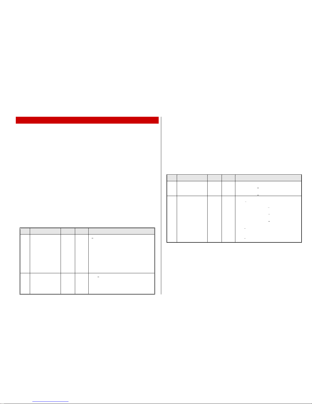
1Overview.................................................................................................................2
2Technical Information...............................................................................................3
3Adressing and Programming....................................................................................5
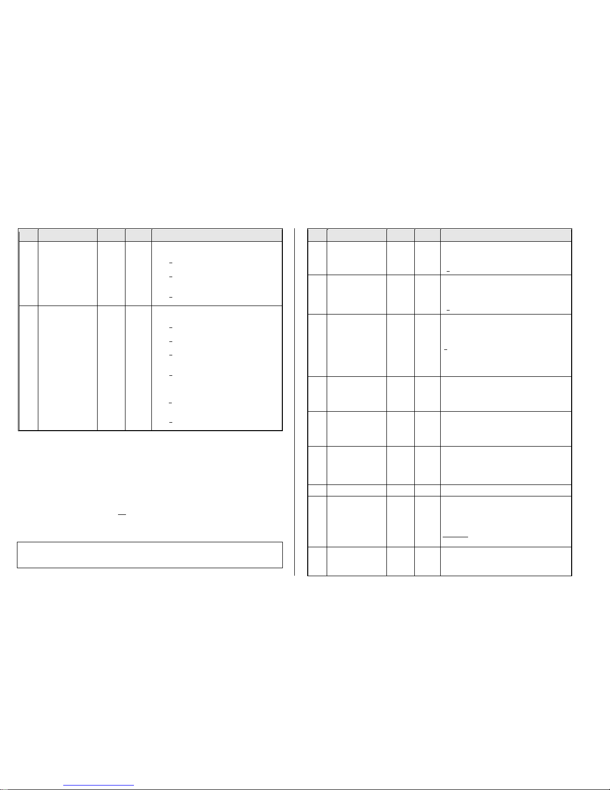
3.1 Programming in “Service mode” (on programming track) .........................................................5
3.2 Programming in “Operations mode” (a.k.a. on-the-main, “PoM“) .............................................5
3.3 Decoder-ID, Load -Code, Decoder-Type and SW-Version.......................................................6
3.4 The (first) vehicle address .........................................................................................................6
3.5 The second address in a function decoder ...............................................................................7
3.6 Analog operation........................................................................................................................7
3.7 “Virtual” motor control and momentum ......................................................................................8
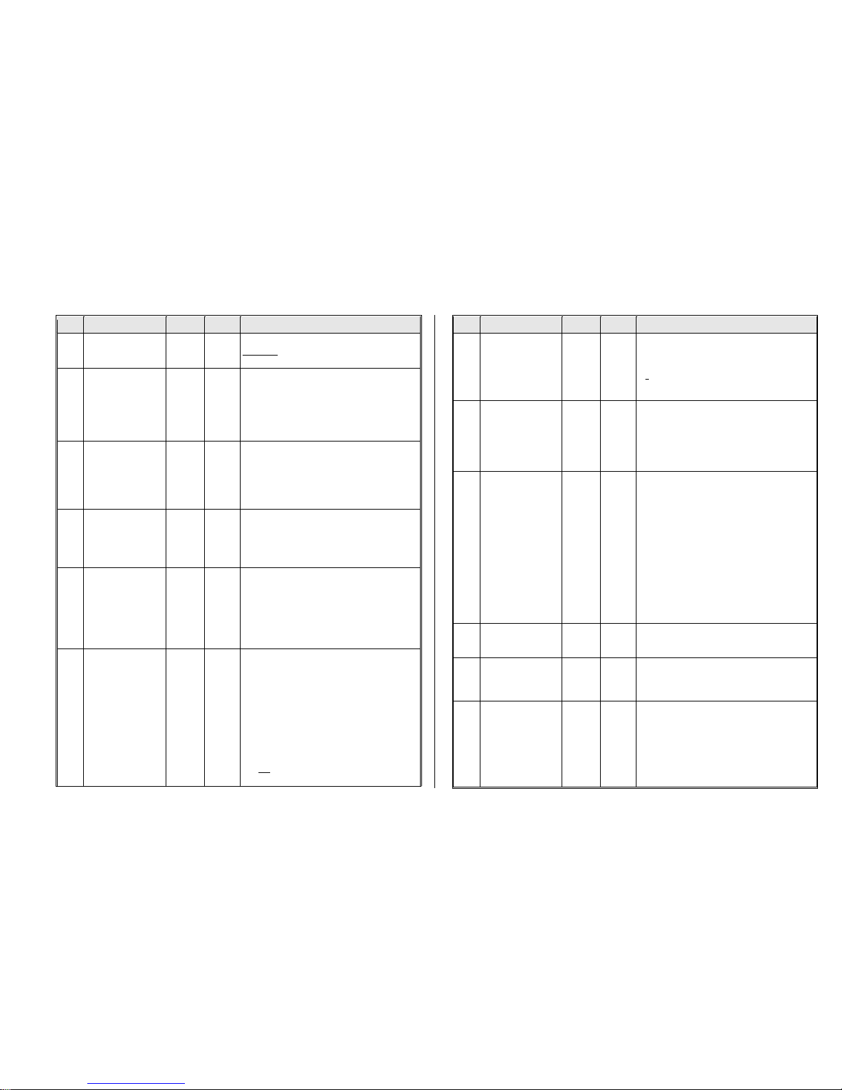
3.8 The NMRA-DCC function mapping .........................................................................................10
3.9 “Unilateral Light Suppression” .................................................................................................11
3.10 The “Swiss Mapping” (SW version 32 and higher)...............................................................11
3.11 Dimming, Low beam and Direction Bits...................................................................................12
3.12 The Flasher Effect....................................................................................................................13
3.13 F1- Pulse Chains (only for old LGB products).........................................................................13
3.14 Special Effects for Function Outputs (US and other lighting effects…) ..................................14
3.15 Configuration of Electric Uncouplers .......................................................................................15
3.16 SUSI-Interface and Logic-Level Output...................................................................................15
3.17 Servo Configuration.................................................................................................................15
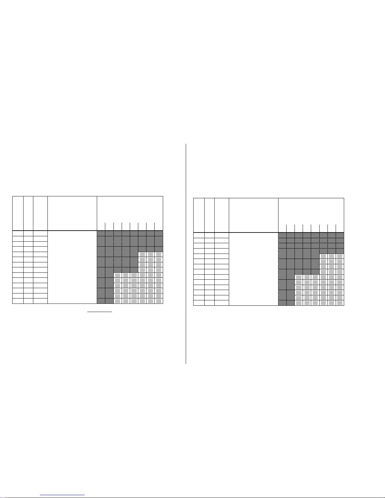
4Feedback - “Bidirectional communication”.............................................................16
5Operating with Märklin MOTOROLA Systems........................................................ 17
6ZIMO Decoder - Software Update.......................................................................... 17
NOTE:
ZIMO decoders contain anEEPROM which stores software that determines its characteristics and functions. The software version can be read out form CV #7 and
#65. The current version may not yet be capable of all the functionsmentioned in this manual. As with other computer programs, it is also not possible for the
manufacturer to thoroughly test this software with all the numerous possible applications. Installing new software versions later can add new functions or correct
recognized errors. SW updates can be done by the end user for all ZIMO decoders since production date October 2004, see chapter “Software Update”! Software
updates are available at no charge if performed by the end user (except for the purchase of a programming module); Updates and/or upgradesperformed by ZIMO
are not considered a warranty repair and are at the expense of the customer. The warranty covers hardware damage exclusively, provided such damage is not
caused by the user or other equipment connected to the decoder. For update versions, see www.zimo.at.
EDITION
First edition --- 2011 08 15
2012 08 15
2015 01 25
2015 02 05
MX688N18 supplement --- 2015 11 16
Swiss Mapping --- 2016 06 23
2018 05 25
2018 07 11

Page 2 Function-Decoders MX681, MX685, MX686, MX687, MX688
1 Overview
Function decoders are locomotive decoders for non-motorized vehicles and are therefore not
equipped with a motor end stage but do offer special features for use in cars usually belonging to a
“block train” pulled or pushed by a locomotive.
The hardware of the MX685 function decoder is based on the loco decoder MX630 (board and hard-
ware is almost identical), the MX686 (on the MX631 until 2012) from 2013 onwards on the MX634
and the miniature function decoder MX681 on the miniature decoder MX621. The dimensions and
most of their features are therefore identical to the decoder they are based on.
A distinctive feature of all ZIMO function decoders is the programmable SECOND ADDRESS (CVs
#64 to #68), which can be used as an alternative address for the coach containing the function de-
coder and is commonly set to the same address as the loco pulling the train. If all coaches of a train
are equipped with such a decoder using the same (second) address, they can all be controlled simul-
taneously with a single key stroke (i.e. the interior light of all coaches are turned ON/OFF with a func-
tion key of the loco address, if that is the second address). With this, the simplest form of a virtual
“train bus” becomes reality, which will certainly play a major role in future digital train technology.
12 x 6.5 x 2 mm 0.7 A -4 Fu-Outputs DCC and DC-Analog (but not MOTOROLA)
MX681
Family
Miniature-Function-Decoder,with reduced ZIMO features; the software does
not contain: MM (Motorola), Servos, SUSI, ZIMO spec. Function mapping.
MX681 plug configurations:
MX681
MX681N
(MX681R)
(MX681F)
7 wires (120mm long) for power pick-up, 4 function outputs. Solder pads are
available for further outputs.
MX681 with 6-pin plug as per NEM651 and NMRA RP 9.1.1., mounted to the
circuit board.
(Versions with 8-pin plug as per NEM652 on 70mm wires
or 6-pin plug on 70mm wires; special order only).
20 x 11 x 3.5 mm 1.0 A - 8 Fu-Outputs -2 Servos - SUSI
MX685
Family
Function-Decoder, compact design for universal applications.
MX685 plug configurations:
MX685
MX685P16
(MX685R)
(MX685F)
7 wires (120mm long) for power pick-up, 4 function outputs. Solder pads are
available for further outputs and for 2 servos or SUSI.
MX685 with 16-pin PluX connector mounted on decoder board.
(Versions with 8-pin plug as per NEM652 on 70mm wires
or 6-pin plug on 70mm wires; special order only).
20.5 x 15.5 x 4mm 1.2A - 8 Fu-Outputs - 2 Servos - SUSI
MX686
Family
High performance Function-Decoder with built-in energy storage circuitry.
MX686 plug configurations:
MX686
MX686D
7 wires (120mm long) for power pick-up, 4 function outputs. Solder pads are
available for further outputs as well as for servo or SUSI.
MX686 with 21-pin “MTC” plug mounted directly on decoder board.
20.5 x 15.5 x 4 mm 1.2 A - 8 Fu-Outputs - 2 Servos - SUSI
MX687
Family
High performance Function-Decoder with built-in energy storage circuitry
and low-voltage output (1.5 V or 5 V).
MX687 plug configurations:
MX687V
MX687W
MX687WD
10 wires (120mm long) for power pick-up, 4 function outputs. Solder pads are
available for further outputs as well as for servo or SUSI. Low voltage output of
1.5V.
Same as MX687V but with 5 V low-voltage output.
Same as MX687V but with 5 V low-voltage output and
21-pin “MTC“ plug mounted on circuit board.
15 x 9.5 x 2.8 mm 0.7 A - 8 Fu-Outputs - 2 Servos - SUSI
MX688
Function-Decoder,only available with Next-18 interface

Function-Decoders MX681, MX685, MX686, MX687, MX688 Page 3
2 Technical Information
Allowable track voltage **) ................................................................................... min. 10 V
MX681 ........................................................................................................… max. 35 V
MX685, MX686, MX687, MX688, MX689…….. DCC and DC-Analog operation . max. 35 V
MX685, MX686, MX687, MX688, MX689 AC-Analog operation .. max. power pulse 50 V
Maximum continuous motor current MX681, MX681R, MX681N ......................................... 0.8 A
MX685, MX685R, MX685P16 ................................. 1.0 A
MX688N18 .................................................................. 0.7 A
MX686, MX686D, MX687V / W / WD, MX689 ............ 1.2 A
Operating temperature ............................................................................................ - 20 to 100 oC
Dimensions (L x W x H) ............ MX681, MX681R, MX681N…………………….. 12 x 8.5 x 2 mm
MX685, MX685R, MX685P16 ………………. 20 x 11 x 3.5 mm
MX686, MX686D……………………………. 20.5 x 15.5 x 4 mm
MX688N18……………………………………... 15 x 9.5 x 2.8 mm
MX687V, MX687W, MX687WD ……...….... 28 x 15.5 x 4 mm
MX689, MX689P22………………………………..30 x 15 x 4 mm
*) The short circuit protection is carried out for the total current of all outputs. Use the “soft start” op-
tion (i.e. CV #125 = 52) to prevent cold-start problems of light bulbs (in-rush current interpreted as a
short circuit, which leads to the output being turned off!
Software - Update:
ZIMO decoders can be updated by the user, provided that one of the following update devices is at
hand: ZIMO decoder update-module MXULF (since 2011), system-cab MX31ZL or command sta-
tion MX10. The updating process is carried out via a USB stick (MXULF, MX31ZL / MX10) or a PC
with Windows operating system and the program ZIMO Firmware Flasher (within the ZIMO Sound
Programmer ZSP).
The same hardware together with the program ZSP is also used to load sound projects into the de-
coder.
There is no need to remove the decoder or to open up the locomotive. Just set the locomotive on
a track section connected to the update module and start the update with the computer or other
equipment mentioned above.

Page 4 Function-Decoders MX681, MX685, MX686, MX687, MX688

Function-Decoders MX681, MX685, MX686, MX687, MX688 Page 5
3 Addressing and Programming
ZIMO decoders can be programmed in
- “Service Mode” (on the programming track) for assigning a new address or reading and writing
CV content but also in
- “Operational Mode” (a.k.a. “Programming on the main” or “PoM”), which is done on the main
track; programming CVs “on the main” is always possible in operational mode. However, an
acknowledgement of successful programming steps or reading out of CVs is only possible with a
DCC system capable of RailCom.
3.1 Programming in “Service mode”(on programming track)
Before programming is actually possible, the decoder must be unlocked with
CV #144 = 0 or = 128 (the latter allows programming but prevents decoder updating).
This is normally the case but in many sound projects the programming lock is activated to prevent ac-
cidental changes. Therefore, it is useful to check that CV, especially when programming attempts
have already failed.
The acknowledgments of successful programming steps on the programming track as well as CV
read-outs are accomplished by power pulses, which the decoder generates by briefly engaging the
motor and/or headlights. If the motor and/or headlights do not draw enough power or don’t draw pow-
er at all (i.e. they are not connected), acknowledgments for successful programming or CV read-outs
are not possible.
To make acknowledgments possible in such cases activate CV #112 bit 1, which enables the decoder
to use an alternate acknowledgment by sending high frequency pulses from the motor end stage.
Whether this method is successful though depends on the DCC system used.
CV
Denomination
Range
Default
Description
#144
Programming and
Update Lock
Note: The programming
lock has no effect on
CV #144, which is there-
fore always accessible
for unlocking.
0,
64,
128,
192
0
= 0: programming and update lock not active
Bit 6 = 1: programming the decoder in „Service
Mode“ is blocked as a protection against
unwanted reprogramming.
Note: Programming in “Operational Mode”is not
locked because any such programming only
applies to the active loco address and
reprogramming the wrong locomotive is
therefore not possible.
Bit 7 = 1: Software updates via MXDECUP, MX31ZL or
other means are locked.
#112
Special ZIMO
configuration bits
0 - 255
2
Bit 1 = 0: Normal acknowledgment in “Service Mode”;
by activating motor and headlight outputs.
= 1: High frequency pulses instead of normal
acknowledgments from motor and headlights.
Bit 2 = 0: Loco number ID is OFF
etc.
3.2 Programming in “Operational mode” (a.k.a. on-the-main, “PoM“)
According to the current NMRA DCC standards it is only possible to program and read CVs on the
main track, but not to assign new vehicle addresses. However, certain DCC systems (among them
ZIMO with the system generation MX10/MX32 and later) will allow addresses to be modified on the
main track with the help of bidirectional communication.
All ZIMO decoders are equipped with bidirectional communication (“RailCom”) and can therefore
(with a corresponding DCC system such as ZIMO MX31ZL and all devices of the new MX10/MX32
generation) read, program and acknowledge successful CV programming steps in operational mode
(on the main track). This requires RailCom to be activated, which is the case if the following CVs are
set as: CV #29, Bit 3 = 1 AND CV #28 = 3
This is usually the default setting, except in certain sound projects or OEM CV sets, in which they need
to be set first.
CV
Denomination
Range
Default
Description
#28
Bi-Directional
Communication
Configuration
0 - 3
3
Bit 0 - RailCom Channel 1 (Broadcast)
0 = OFF 1 = ON
Bit 1 - RailCom Channel 2 (Data)
0 = OFF 1 = ON
#29
Configuration Data #1
0 - 63
14 =
0000 1110
Bit 3 = 1
(“RailCom” is
activated)
Bit 0 - Train direction:
0 = normal, 1 = reversed
Bit 1 - Number of speed steps:
0 = 14, 1 = 28
Bit 2 - DC operation (analog): *)
0 = disabled 1 = enabled
Bit 3 - RailCom (“bidirectional communication“)
0 = deactivated 1 = activated
Bit 4 - Individual speed table:
0 = off, CV #2, 5 and 6 are active.
1 = on, according to CV ‘s # 67 – 94
Bit 5 - Decoder address:
0 = primary address as per CV #1
1 = ext. address as per CV #17+18
*Broadcast: Decoder sends information without being requested
Data: Decoder sends information only upon request.

Page 6 Function-Decoders MX681, MX685, MX686, MX687, MX688
3.3 Decoder-ID, Load -Code, Decoder-Type and SW-Version
CV
Denomination
Range
Default
Description
#250,
#251,
#252,
#253
Decoder-ID
also contains a code (in
CV #250) that identifies
the decoder type
Read only
-
The decoder ID (serial number) is automatically entered
during production: The first Byte (CV #250) denotes the
decoder type; the three other Bytes contain the serial
number.
The decoder ID is primarily used for automatic address
recognition when an engine is placed on the layout
track (future function) as well as in conjunction with the
“load code” for “coded” sound projects (see CV #260 -
263).
#8
Manufacturer ID
and
HARD RESET
or
ACTIVATION
of special CV sets
Read only
For pseudo
programming
see “Descrip-
tion” column
on the right.
145
( = ZIMO)
Reading out this CV always result in “145”
(”10010001”), the number issued for ZIMO by the
NMRA.
This CV is also used to reset the decoder by Pseudo-
Programming.
Pseudo-Programming means that the entered value is not
really stored, but rather used to start a defined action.
CV #8 = “8” HARD RESET (NMRA standard);
all CVs reset to the last active CV set, or the default
values listed in this CV table if no such set was active.
CV #8 = “9” HARD RESET for old LGB-operation
(14 speed steps, pulse chain commands).
Further options: see chapter “CV Sets”!
#7
Manufacturer Version
No.
(SW-Version)
Also see CV #65 for
Sub-Version Number
and
special procedures for pro-
gramming with “Lokmaus-2”
and other “low level” sys-
tems
Read only
Pseudo-
programm.
see explana-
tion to the right
-
This CV holds the version number of the firmware cur-
rently in the decoder.
With the help of “Pseudo-programming” it also helps to
program decoders with DCC systems of limited range:
Ones digit = 1: Subsequent programming value + 100
= 2: ... + 200
Tens digit = 1: Subsequent CV number + 100
= 2: … + 200
etc. = 9: … + 900
Hundreds digit = 0: Revaluation applies only once
= 1: Revaluation applies until power-off
#65
SW-
Sub-Version Number
Also see CV #7 for
Version Number
Read only
-
This CV indicates a possible sub-version number of the
main version noted in CV #7.
The entire SW version number is thus composed of
CV #7 and #65 (i.e.: 28.15).
3.4 The (first) vehicle address
Decoders are usually programmed at delivery to address 3 (CV #1 = 3), for the DCC as well as the
MM (Märklin Motorola) format. All aspects of operation are possible with this address but it is recom-
mended to change to a different address as soon as possible.
The DCC address range goes up to 10239 and therefore exceeds the range of a single CV. Ad-
dresses higher than 127 are stored in CV #17 and #18. Bit 5 in CV #29 is used to select between the
short address in CV #1 and the long address in CVs #17/18.
Most digital systems (with the possible exception of very old or simple products) calculate the value
for the CV’s involved automatically and also set Bit 5 in CV #29 to the proper value when writing the
address, so that the user does not have to deal with the necessary coding.
CV
Denomination
Range
Default
Description
#1
Primary (short) Address
DCC:
1 - 127
MM:
1 - 80
3
The “short” (1-byte) loco address (DCC, MM).
In the case of DCC:
The address in CV #1 is only valid if CV #29, Bit 5 = 0.
If CV #29 Bit 5 = 1, the long address in CV #17 + #18 is
used.
#17
+
#18
Extended (long)
address
128
-
10239
0
The long DCC address applies to addresses >127.
It is only active if CV #29 Bit 5 = 1.
#29
Configuration Data #1
0 - 63
14 =
0000 1110
with
Bit 5 = 0
(for short
address)
Bit 0 - Train direction:
0 = normal, 1 = reversed
Bit 1 - Number of speed steps:
0 = 14, 1 = 28
Bit 2 - DC operation (analog): *)
0 = disabled 1 = enabled
Bit 3 - RailCom („bidirectional communication“)
0 = deactivated 1 = activated
Bit 4 - Individual speed table:
0 = off, CV #2, 5 and 6 are active.
1 = on, according to CV s #67 –94
Bit 5 - Decoder address selection:
0 = short address as per CV #1
1 = long address as per CV #17+18
Decoder-controlled consisting (a.k.a. “Advanced consisting”)
Combined operation of two or more locomotives (consisting) can be organized by
- the DCC system (common practice with ZIMO systems, without changing any CVs) or
- by the following CVs, which can be programmed manually or managed by the DCC system (often the
case with American systems).
This chapter covers only the latter; the decoder controlled consisting!

Function-Decoders MX681, MX685, MX686, MX687, MX688 Page 7
CV
Denomination
Range
Default
Description
#19
Consist address
0 - 127
0
A common consist address for 2 or more engines can
be entered in this CV to each loco of the same consist.
If CV #19 > 0: Speed and direction is governed by this
consist address (not the individual address in CV #1 or
#17+18); functions are controlled by either the consist or
individual address, see CV’s #21 + 22.
#21
Consist addr active for
F1 - F8
0 - 255
0
Functions defined here will be controlled by the consist
address.
Bit 0 = 0: F1 controlled by individual address
= 1: …. by consist address
Bit 1 = 0: F2 controlled by individual address
= 1: …. by consist address
………. F3, F4, F5, F6, F7
Bit 7 = 0: F8 controlled by individual address
= 1: …. by consist address
,
#22
Consist addr active for
FL-F9-F27
0 - 63
0
Select whether headlights and/or functions F9 –F12 are
controlled via consist address or individual address.
Bit 0 = 0: F0 (forw.) controlled by individual address
= 1: …. by consist address
Bit 1 = 0: F0 (rev.) controlled by individual address
= 1: …. by consist address
Bit 2 = 0: F9 controlled by individual address
= 1: …. by consist address
Bit 3 = 0: F10 controlled by individual address
= 1: …. by consist address
Bit 4 = 0: F11 controlled by individual address
= 1: …. by consist address
Bit 5 = 0: F12 controlled by individual address
= …. by consist address
3.5 The second address in a function decoder
The second address in CV #64 (short) or CV #67+68 (long)
is used as an alternative address for cars or coaches equipped with a function decoder. The second
address is usually the decoder address of a locomotive. If all coaches of a train are equipped with
function decoders using the loco address as the second address, the lights of all coaches can for ex-
ample be turned ON/OFF with a single loco function key.
See chapter “Function mapping”.
The “virtual motor control” follows the commands of the second address, if one is defined (value > 0).
CV
Denomination
Range
Default
Description
#64
Short
SECOND ADDRESS
1 - 127
0
The “short” (1-byte) second address;
it is active when CV #112, Bit 5 = 0.
#67
#68
Long
SECOND ADDRESS
128 -
10239
0
The “long” second address;
it is active when CV #112, Bit 5 = 1.
Note: In contrast to the “first long address”, the cab can-
not calculate the proper CV values automatically.
As a work around, program the desired second address
temporarily as the first address. Then read out CV’s
#17/18 and enter these values in CV’s #67/68. Program
the first address back to the original address, if used.*
#112
Special ZIMO
configuration bits
0, 8, 32,
40
2
Bit 1 = 0: Normal “service mode” acknowledgement.
= 1: Special “high frequency”acknowledgement;
because LEDs typically don’t draw enough
current for “service mode” acknowledgement.
Bit 5 = 0: Select between “short” or
= 1: “long” second address
*The calculation is explained on the last page of this instruction manual
3.6 Analog operation
All ZIMO decoders are capable of operating on conventional layouts operated with DC power packs, in-
cluding PWM throttles, in analog DC as well as in analog AC (Märklin including the high voltage pulse
for direction change).
To allow analog operation CV #29, Bit 2 = 1
must be set.
CV
Denomination
Range
Default
Description
#29
Configuration Data #1
0 - 63
14 =
0000 1110
includes
Bit 2 = 1
(Analog
operation
enabled)
Bit 0 - Train direction:
0 = normal, 1 = reversed
Bit 1 - Number of speed steps:
0 = 14, 1 = 28
Bit 2 –Automatic switchover to analog:
0 = disabled 1 = enabled
Bit 3 - RailCom (“bidirectional communication“)
0 = deactivated 1 = activated
Bit 4 - Individual speed table:
0 = off, CV #2, 5 and 6 are active.
1 = on, according to CV s #67 –94
Bit 5 - Decoder address:
0 = primary address as per CV #1
1 = ext. address as per CV #17+18

Page 8 Function-Decoders MX681, MX685, MX686, MX687, MX688
CV
Denomination
Range
Default
Description
#13
Alternate Mode
Function Status
F1- F8
0 - 255
0
Select the functions that should be ON during analog
operation.
Bit 0 = 0: F1 OFF in analog mode
= 1: …ON…
Bit 1 = 0: F2 OFF in analog mode
= 1: …ON…
………. F3, F4, F5, F6, F7
Bit 7 = 0: F8 OFF in analog mode
= 1: …ON…
#14
Alternate Mode
Function. Status
F0, F9-F12
and
acceleration,
deceleration and motor
control in analog
0 - 255
67,
that is
Bit
0, 1, 6 = 1
Select the functions that should be ON during analog
operation.
Bit 0 = 0: F0 (forward) OFF in analog mode
= 1: …ON…
Bit 1 = 0: F0 (reverse) OFF in analog mode
= 1: …ON…
Bit 2 = 0: F9 OFF in analog mode
= 1: …ON…
………. F10, F11
Bit 5 = 0: F12 OFF in analog mode
= 1: …ON…
Bit 6 = 0: Analog operation with momentum as per
CVs #3 + 4; often needed for sound
= 1: Analog operation without momentum from
CVs #3 + 4; immediate response to track
voltage similar to classic analog control.
Bit 7 = 0: Analog operation without motor regulation.
= 1: Analog operation with motor regulation.
3.7 “Virtual” motor control and momentum
Even though function decoders don’t have an actual motor output, they can still be programmed with pa-
rameters for “virtual motor control”, in order to synchronize the actions of the function decoder with the
loco decoder, provided the first or second address of the function decoder is identical with the loco de-
coders. This is especially important during acceleration or deceleration, for example, when activating the
direction key without first stopping the train. It makes sense to use the same settings in these CV's as are
used in the locomotive decoder.
However, the 28-speed point curve is not available, only the three-point curve, because the relevant CV
numbers are used for the second address. For this reason, Bit 4 in CV #29 is also not available. And of
course, CV settings that relate to motor feedback are unnecessary.
For many applications though, the motor control CVs are not important
in function decoders. Setting CV #3 and #4 to match the CVs
of the loco decoder is sufficient.
CV
Denomination
Range
Default
Description
#2
Vstart
with 3-step curve
1 - 255
1
Internal speed step (1 … 255) applied as
lowest external speed step (= speed step 1)
(applies to 14, 28, or 128 speed step modes)
= 1: lowest possible speed
#5
Vhigh
with 3-step curve
0 - 255
1
or
255
Internal speed step (1 … 255) applied as
highest external speed step
(14, 25 or 128, depending on the speed step mode
selected in CV # 29, Bit 1)
= 1 (same as 255): fastest speed possible.
#6
Vmid
1,
¼ to ½
of the
value in
CV #5
1
(= @ 1/3 of
top speed)
Internal speed step (1 … 255) applied as
medium external speed step (that is, speed step 7,
14 or 63 depending on the speed step mode selected
in CV #29, Bit 1)
”1" = default curve (Medium speed is set to one third of
top speed, i.e., if CV #5 = 255 the curve is the same as
if CV #6 would be programmed to 85)
The speed curve resulting from CV #2, 5 and 6 is auto-
matically smoothed out to prevent kinks.
#3
Acceleration rate
0 - 255
2
The value multiplied by 0.9 equals acceleration time in
seconds from stop to full speed.
The effective default value for sound decoders is usual-
ly not the value given here, but is determined by the
loaded sound project.
#4
Deceleration rate
0 - 255
1
The value multiplied by 0.9 equals deceleration time in
seconds from full speed to a complete stop.
The effective default value for sound decoders is usual-
ly not the value given here, but is determined by the
loaded sound project.
#23
Acceleration Adjustment
0 - 255
0
To temporarily increases the acceleration rate to a new
load or when used in a consist.
Bit 0-6: entered value increases or decreases
acceleration time in CV #3.
Bit 7 = 0: adds above value to CV #3.
= 1: subtracts above value from CV #3.
#24
Deceleration Adjustment
0 - 255
0
As above, but for deceleration and therefore CV #4.
#121
Exponential
Acceleration
0 - 99
0
Acceleration time (momentum) can be stretched in the
lower speed range:
Tens digit: Percentage of speed range to be
included (0 to 90%).
Ones digit: Exponential curve (0 to 9).
EXAMPLE:
CV #121 = 11, 23 or 25 are typical initial test values.
#122
Exponential
Deceleration
0 - 99
0
Deceleration time (momentum) can be stretched in the
lower speed range:
Tens digit: Percentage of speed range to be
included (0 to 90%).

Function-Decoders MX681, MX685, MX686, MX687, MX688 Page 9
CV
Denomination
Range
Default
Description
Ones digit: Exponential curve (0 to 9).
EXAMPLE:
CV #122 = 11, 23 or 25 are typical initial test values.
#49
Signal controlled
(HLU)
acceleration
0 - 255
0
Entered value multiplied by 0.4 equals acceleration time
in seconds from stop to full speed
when:
“ZIMO signal controlled speed influence” with ZIMO
MX9 track section module, StEin or successor
or
“asymmetrical DCC signal” method (Lenz ABC) is em-
ployed
#50
Signal controlled
(HLU)
deceleration
0 - 255
0
Entered value multiplied by 0.4 equals deceleration time
in seconds from full speed to complete stop when:
“ZIMO signal controlled speed influence” with
ZIMO MX9 track section module, StEin or successor
or
“asymmetrical DCC signal” method (Lenz ABC) is em-
ployed
#51
#52
#53
#54
#55
Signal controlled
(HLU) speed limits
#52 for “U”,
#54 for “L”,
#51, 53, 55
for intermediate steps
0 - 255
20
40 (U)
70
110 (L)
180
ZIMO “signal controlled speed influence” method (HLU)
using MX9, StEin or successor:
Defines the internal speed steps for each of the 5 speed
limits generated via HLU.
#59
Signal controlled
(HLU)
delay
0 - 255
5
ZIMO signal controlled speed influence (HLU) with
ZIMO MX9 track section module, StEin or future module
or
when using the “asymmetrical DCC signal” stopping
method (Lenz ABC):
Time in tenths of a second until the locomotive starts to
accelerate after receiving a higher signal controlled
speed limit command.
#27
Decoder Automatic
Stopping
Configuration
(Lenz “ABC” method
0, 1, 2, 3
0
Bit 0 = 1: Stops are initiated if voltage in right rail
is higher than in left rail (in direction of
travel). This setting, CV #27 = 1, IS THE
COMMON APPLICATION for this
feature (provided the decoder is wired
correctly to the rail).
Bit 1 = 1: Stops are initiated if voltage in left rail
is higher than in right rail (in direction of
travel).
Stopping is directional if only one of the two bits is set
(not both). Traveling in the opposite direction will have
no effect. Use the other bits In case the train stops in the
wrong direction!
Bit 0 and Bit 1 = 1 (CV #27 = 3): Stops in both
directions, regardless of rail polarity.
CV
Denomination
Range
Default
Description
#134
Asymmetrical
threshold
for
stopping with
asymmetrical
DCC signal
(Lenz ABC method).
1 - 14,
101 - 114,
201 - 214
=
0,1 - 1,4 V
106
Hundreds digit: Sensitivity adjustment, changes the
speed with which the asymmetry is being recognized.
= 0: fast recognition (but higher risk of errors,
i.e. unreliable stopping).
= 1: normal recognition (@ 0.5 sec.), pretty save
results (default).
= 2: slow recognition (@ 1 sec.), very reliable.
#29,
#124,
#112
Individual bits in these
CVs are responsible for
the correct reaction to
“DC” and “Märklin”
brake sections.
-
-
Set the following CVs for polarity dependent DC brake
sections:
CV #29, Bit 2 = 0 and CV #124, Bit 5 = 1.
For polarity independent brake sections (“Märklin-
Brake sections”)set
CV #29, Bit 2 = 0 and CV #124 , Bit 5 = 1 and
additionally CV #112, Bit 6 = 1.
#124
Shunting key
functions:
Low gear (half speed)
and
Momentum reduction
or deactivation
NOTE:
Extended shunting key
selection in
CV’s #155, 156
Bits
0 - 4, 6
0
Select a function key for
LOW GEAR ACTIVATION:
Bit 4 = 1 (and Bit 3 = 0): F3 as half-speed key
Bit 3 = 1 (and Bit 4 = 0): F7 as half-speed key
Select a function key for
MOMENTUM DEACTIVATION:
Bit 2 = 0 (and Bit 6 = 0): “MN” key for deactivation,
Bit 2 = 1 (and Bit 6 = 0): F4 key for deactivation
Bit 6 = 1 (Bit 2 is irrelevant): F3 for deactivation.
Effect of above key (MN, F3 or F4) on
MOMENTUM:
Bit 1, 0 = 00: no effect on momentum
= 01: removes momentum of
CV #121 + #122
= 10: CV #3 + #4 reduced to ¼.
= 11: removes all momentum above.
#155
Selecting a function key
as half-speed key
0 - 19
0
Expanding on the settings of CV #124, if another key is
required than F3 or F7.
Consult the loco decoder manual for more information.
#156
Selecting a function key
for deactivating
momentum
0 - 19
0
Expanding on the settings of CV #124, if another key
than F3, F4 or MAN is required for momentum deactiva-
tion.
Consult the loco decoder manual for more information.
#157
Selecting a function key
for the
MAN function
Only for non-ZIMO
systems, which don’t
have the MN key.
0 - 19
0
The MAN function (or MAN key on ZIMO cabs) was
originally designed for ZIMO applications only, in order
to cancel stop and speed limit commands applied by the
signal controlled speed influence system (HLU).
This function was expanded in later software versions to
include “asymmetrical DCC signal stops” (Lenz ABC).
If ZIMO decoders are used with non-ZIMO systems, a
function key can now be assigned with CV #157 to can-
cel a signal controlled speed limit or stop command.

Page 10 Function-Decoders MX681, MX685, MX686, MX687, MX688
3.8 The NMRA-DCC function mapping
CVs #33 to #46 are reserved for the function mapping of the first address. It links a specific function
key to a specific function output. It is also possible to control several function outputs with one func-
tion key. Each function key is represented by a single CV in the in the table below. The individual bits
of a CV represent individual function outputs.
Due to the fact that function decoders have a maximum of 8 function outputs (headlights, FA1-FA6),
the "superfluous" bits (see table below) are shifted to the left (according to NMRA rules), so that "low"
function outputs (FA0v / r, FA1) can also be controlled by "high" function keys (F3 and higher).
Below: NMRA standard bits (dark gray boxes) and “right shifted” bits (shaded gray):
NMRA Function
CV
Number key
on ZIMO
cabs
Function outputs;
FA6
FA5
FA4
FA3
FA2
FA1
Rear
light
Front
light
F0
#33
1 (L) fw
7
6
5
4
3
2
1
0
F0
#34
1 (L) re
7
6
5
4
3
2
1
0
F1
#35
2
7
6
5
4
3
2
1
0
F2
#36
3
7
6
5
4
3
2
1
0
F3
#37
4
4
3
2
1
0
7
6
5
F4
#38
5
4
3
1
0
7
6
5
F5
#39
6
4
3
2
1
0
7
6
5
F6
#40
7
4
3
2
1
0
7
6
5
F7
#41
8
1
0
7
6
5
4
3
2
F8
#42
9
1
0
7
6
5
4
3
2
F9
#43
0
1
0
7
6
5
4
3
2
F10
#44
1
1
0
7
6
5
4
3
2
F11
#45
2
1
0
7
6
5
4
3
2
F12
#46
3
1
0
7
6
5
4
3
2
The black dots in the table above indicate the default settings at the time of delivery, where each func-
tion key corresponds to the same numbered function output. Therefore, the following values were writ-
ten to these CV’s by default:
CV #33 = 1
CV #34 = 2
CV #35 = 4
CV #36 = 8
CV #37 = 2
CV #38 = 4
CV #39 = 8
CV #40 = 16
and so on
The Function mapping for the Second address is defined (in the same way as for the first
address) with CVs #69 to #82
The commands of the first and the second address are read separately, and stored according to the
respective "function mapping" and the desired function output states.
After power-on (system boot-up, longer track power interruption etc.), the decoder is first waiting for a
SECOND ADDRESS command (provided the second address is not 0) and the outputs are set based on
this secondary address command. (First-address commands are executed only if changes in the function
output states between successive first-address commands occur.) During continued operation the "prin-
ciple of the most recent change" between first and second address commands applies.
Identical to the first address: NMRA standard bits (dark gray) and “right shifted” bits (shaded gray):
NMRA Function
CV
Number key
on ZIMO
cabs
Function outputs
Function outputs;
FA6
FA5
FA4
FA3
FA2
FA1
Rear
light
Front
light
F0
#69
1 (L) fw
7
6
5
4
3
2
1
0
F0
#70
1 (L) re
7
6
5
4
3
2
1
0
F1
#71
2
7
6
5
4
3
2
1
0
F2
#72
3
7
6
5
4
3
2
1
0
F3
#73
4
4
3
2
1
0
7
6
5
F4
#74
5
4
3
1
0
7
6
5
F5
#75
6
4
3
2
1
0
7
6
5
F6
#76
7
4
3
2
1
0
7
6
5
F7
#77
8
1
0
7
6
5
4
3
2
F8
#78
9
1
0
7
6
5
4
3
2
F9
#79
0
1
0
7
6
5
4
3
2
F10
#80
1
1
0
7
6
5
4
3
2
F11
#81
2
1
0
7
6
5
4
3
2
F12
#82
3
1
0
7
6
5
4
3
2
Tip: Directional taillights with the help of special effect CV’s:
With the NMRA function mapping only F0 can be directional and was intended for the headlights, so
they automatically switch between “front” and “rear” when the driving direction is changed. All other
functions are controlled direction-independent.
The special effect CVs #125 - 132, #159 and #160 (see chapter “Special function output effects”),
each assigned to a function output (up to FO8), make it possible to have more direction dependent
functions. To utilize only the directional capabilities of these CVs use only the directional Bits 0 and/or
1 without setting the actual effect-bits.

Function-Decoders MX681, MX685, MX686, MX687, MX688 Page 11
Example 1: A couple of red taillights are connected to function outputs FO1 and FO2 (front and
rear). Both are to be actuated with F1 but should also change direction-dependently. This requires the
following CV settings:
CV #35 = 12 (Bit 2 for FO1 and Bit 3 for FO2), as well as
CV #127 = 1 (for FO1) and CV #128 = 2 (for FO2).
therefore FO1 is only activated in forward direction and FO2 only in reverse, and only if the function is
turned ON with the function key F1.
Example 2: Contrary to example 1 where the red taillights were switched independently from the
white headlights, in this example the headlights and taillights are switched ON/OFF together at the
proper end of the locomotive with F0 or F1 (depending on which end the loco is coupled to the train).
This can be done as follows:
Connect: White front headlights to function output “front headlights”
Red front taillights to function output FO2
White rear headlights to function output FO1
Red rear taillights to function output “rear headlights”.
CV #33 = 1 and CV #34 = 8 front white headlights on F0forw and front red taillights on F0rev
CV #35 = 6 both white headlights as well as red taillights in the rear on F1
CV #126 = 1 / CV #127 = 2 (Direction dependence for rear white and red lights by means of “Special
Effects” CV).
Alternative method: CV’s #107, #108 for “One-sided light suppression”, see below!
3.9 “Unilateral Light Suppression”
This is another feature, asked for by many users, that makes it possible to switch off all lighting on
one side of a locomotive per one function key (usually on the “train side”, i.e. where cars are coupled
to the locomotive).
CV
Denomination
Range
Default
Description
#107
Light suppression
(i.e. front headlights
AND additionally de-
fined function output)
at
cab side 1 (front)
0 - 255
0
The value of this CV is calculated as follows:
The number of a function output (FO1…FO28) x32
+ number of a function key (F1, F2…F28)
= Value of CV #107
Function Key: That key (F1…F28) which should turn
off ALL lights on the cab side 1 (front side) AND
Function Output: i.e. taillights on the same side.
#108
Cab side 2 (rear)
0 - 255
0
Same as CV #107 but for other locomotive side.
3.10 The “Swiss Mapping” (SW version 32 and later)
The “Swiss mapping” is a function mapping that allows the loco lighting to be used as required by
Swiss prototypical locomotives, which of course is also useful for locos of other countries.
The purpose of the "Swiss mapping" is to switch various states of the locomotive lighting with different
function keys, i.e. for situations like driving a single locomotive, cars coupled on driver’s cab 1, or at
the driver's cab 2, push-pull, shunting, etc.
Using this relatively complex method is of course only expedient if the vehicle is equipped with many
independently connected lights (or LED’s) and the decoder offers as many function outputs (it should
at least be 6). ZIMO decoders indeed offer between 6 and 10 function outputs (with the exception of a
few miniature decoders), large-scale decoders even more.
The desired lighting states are defined by a total of 17 CV groups, each group containing 6 CV’s
(CV #430 - #477). The principle is simple in itself, in that the first CV of each group contains the num-
ber (1 to 28) for a function key F1 .. F28, and the other CVs define which function outputs are to be
switched on when pressing this key, each dependent on the direction of travel.
CV
Denomination
Range
Default
Description
#430
Swiss Mapping Group 1
“F-Key”
0 - 28,
29 (for F0),
129 - 157
0
The key defined here shall turn on the function outputs
listed under
A1 (forward or reverse) and
A2 (forward or reverse).
1 –28 for function keys F1 –F28, F29 is for F0.
Bit 7 = 1: Inverts the F-key function.
Bit 6 = Swiss Mapping group applies to secondary ad-
dress.
#431
Swiss Mapping Group 1
“M-Key”
or
Special high-beam
setting
Bit 0 - 6:
0 - 28,
29 (for F0)
and
Bit 7
or 255
0
The “normal function mapping” (according to CVs
#33-#46) for the “M-key” defined here will be deac-
tivated (that is the assigned outputs) when the “F-key”
is switched on.
Bit 7 = 1: the outputs listed under A1 and A2 should
only switch ON if the F and M key are ON.
Bit 6 = 1: The M-key outputs shall not be turned OFF if
the F-key is ON and driving forward.
Bit = 5: The M-key outputs shall not be turned OFF if
the F-key is ON and driving backwards.
= 157: is an often used value for this CV, because
F0 (= 29) is usually selected as the “M-key” with
Bit 7 = 1. F0 then acts as a general ON/OFF key.
= 255 (Special high-beam setting!): the Fu-Outputs
defined in the following four CVs are switched to full
intensity, provided that they are controlled via the
"normal function mapping", and dimmed with CV #60;
this function is used, for example, to switch the head-
lights of a Swiss locomotive to high-beam, without
switching the white taillight to high-beam.
Depending on CV #399 setting: High beam is only
switched on if the speed is higher than the value given
in this CV.

Page 12 Function-Decoders MX681, MX685, MX686, MX687, MX688
#432
Swiss Mapping Group 1
“A1” forward
Bits 0 - 3:
1 - 12
14 (FO0f)
15 (FO0r)
Bits 5 - 7:
0 - 7
0
Bits 0 - 3:
Function output to be switched ON in forward direction
provided that both the “F” and “M” keys are ON (if Bit 7
for the “M” key of this group is 1, otherwise “F” key ON
is sufficient).
Bits 7, 6, 5 (7 possible values or zero):
Number of the applicable dimming CV. For example:
Bit 5 = 1 means dimming according to CV #508 etc.
#433
Swiss Mapping Group 1
“A2” forward
Bits 0 - 3:
1 - 12
14 (FO0f)
15 (FO0r)
Bits 5 - 7:
0 - 7
0
Bits 0 - 3:
Additional function output to be switched ON in for-
ward direction provided that both the “F” and “M” keys
are ON (if Bit 7 for the “M” key of this group is 1, oth-
erwise “F” key ON is sufficient).
Bits 7, 6, 5 (7 possible values or zero):
Number of the applicable dimming CV. For example:
Bit 5 = 1 means dimming according to CV #508 etc.
#434
Swiss Mapping Group 1
“A1” reverse
As above
0
As above but for reverse direction
#435
Swiss Mapping Group 1
“A2” reverse
As above
0
As above but for reverse direction
#436 -
441
. . . Group 2.
. . .
0
All 6 CVs of Group 2 are defined the same way as the
6 CVs in group 1.
#442 -
447
. . . Group 3.
. . .
0
All 6 CVs of the following groups are defined the same
way as the 6 CVs in group 1.
#448 -
477
. . . Group 4 to 8.
. . .
0
. . .
#508
#509
#510
#511
#512
Dimming values for
“Swiss Mapping”
(0- 31)*8
(only Bits
7 - 3 are
used)
0
Each group CV (i.e. #432, 433, 434, 435) can be
linked to one of these five dimming CVs. The value to
enter is the dimming value (0 –31) times the function
output number. (i.e. dimming value = 16 for function
output 6: 16 x 6 = 96 is the value to enter).
This will dim the relevant function outputs accordingly.
Only with function outputs FO0 to FO8.
3.11 Dimming, Low beam and Direction Bits
Some elements connected to function outputs often are not designed to operate with full track power,
as is the case with 18V bulbs at 24V track voltage (quite common on large scale model railroads).
Other times the brightness needs to be reduced simply because the light is too bright.
The best solution in such cases is to connect the positive pole of such devices to the low voltage sup-
ply of the decoder (see chapter “Technical Information”). Such low-voltage outputs are fully stabilized
and the voltage will not fluctuate with changes in track voltage.
Alternatively or in addition to this (the dimming effect is not limited to devices connected to full track
power but also works with low voltage), the PWM (pulse width modulation) voltage reduction is also
available with CV #60,
which defines the PWM duty cycle. Of course, this kind of voltage reduction is also interesting be-
cause it is easy to change at any time.
NOTE: Bulbs with voltage ratings as low as 12V can be dimmed with this PWM dimming function with-
out damage even if track voltages are considerably higher; but not bulbs rated below that such as 5V or
1.2V bulbs. These must be connected to one of the decoder’s low voltage supply pins instead of a nor-
mal positive pin (see chapter “Installation and Wiring”).
LEDs, on the other hand, require a series resistor; if however, the resistor is designed to operate at
5V, the PWM dimming is also sufficient at a track voltage of 25V (in this case the setting would be
CV #60 = 50, so a reduction by one fifth).
CV #60 generally affects all function outputs. The dimming function can be restricted to specific func-
tion outputs using the following dim mask CVs.
CV
Denomination
Range
Default
Description
#60
Reduced function output
voltage
(Dimming).
Affects all
function outputs.
0 - 255
0
Reduction of function output voltage with PWM (pulse-
width modulation). Useful for example for headlight
dimming.
Example values:
CV #60 = 0 or 255: full voltage
CV #60 = 170: 2/3 of full voltage.
CV #60 = 204: 80% of full voltage.
#114
Dim Mask 1
=
Excludes certain
function outputs from
dimming per CV #60.
For higher function
outputs go to
CV #152.
Bits
0 - 7
0
Enter function outputs that are not to be dimmed as
per CV #60. These outputs will use the full voltage
available from the decoder’s positive pin.
Bit 0 - front headlight,
Bit 1 - rear headlight,
Bit 2 - function output FO1, Bit 3 - FO2,
Bit 4 - function output FO3, Bit 5 - FO4
Bit 6 - function output FO5, Bit 7 - FO6
Bit value = 0: Output will be dimmed to the value
defined in CV #60.
Bit value = 1: Output will not be dimmed.
#152
Dim Mask 2
Continuation of
CV #114
Bits
0 - 5
… Continuation of CV #114.
Bit 0 - function output FO7,
Bit 1 - function output FO8,
Bit 2 - function output FO9,

Function-Decoders MX681, MX685, MX686, MX687, MX688 Page 13
and
FO3, FO4 as direction
bit mapping
and
Bit 6,
Bit 7
0
0
Bit 3 - function output FO10,
Bit 4 - function output FO11,
Bit 5 - function output FO12.
Bit 6 = 0: „normal“
= 1: “Direction bit” at FO3 and FO4 that is,
FO3 is switched on when driving in reverse,
FO4 is switched on when driving forward
(normal mapping of FO3 and FO4 is invalid
when this Bit is set).
Low/high beam with the help of the low beam mask
One of the two function keys F6 (CV #119) or F7 (CV #120) can be defined as a low beam key. Spe-
cific function outputs can be dimmed whit the output turned ON or OFF (inverted action with Bit 7).
CV
Denomination
Range
Default
Description
#119
Low beam mask for F6
-
Output assignment for
(example) low/high
beam
headlights
ATTENTION:
Certain settings in
CV #154 (Special output
configurations) change
the meaning of CVs
#119 and #120 and
therefore will no longer
work as a low-beam
mask.
Bits
0 - 7
0
Selected function outputs will dim with F6 key, accord-
ing to the dim value in CV #60.
Typical application: Low/high beam
Bit 0 - front headlight,
Bit 1 - rear headlight,
Bit 2 - function output FO1,
Bit 3 - function output FO2,
Bit 4 - function output FO3,
Bit 5 - function output FO4.
Bit value = 0: Output will not be dimmed,
Bit value = 1: Output will be dimmed with F6 to value
defined in CV #60.
Bit 7 = 0: normal action of F6.
= 1: inverted action of F6.
EXAMPLE:
CV #119 = 131: Function key F6 toggles headlights
between low and high beam.
#120
Low beam mask for F7
Bits 0 - 7
Same as CV #119 but with F7 as low beam key.
A “second dim value” with the help of the uncoupler- CV
If more function outputs need to be dimmed than CV #60 allows or if some function outputs require a
different voltage and the uncoupler function is not needed on the same vehicle then
CV #115
can be used for an alternative low voltage supply. The respective function outputs must be defined as
“uncoupler output” in the corresponding
CVs #125…#132, #159 and #160
(see “Special effects for function outputs).
CV
Denomination
Range
Default
Description
#115
Uncoupler control
or
Second dim value
0 - 9
0
Only active as uncoupler if “uncoupler” function is se-
lected (value 48) in CV #125 …132, 159 or 160:
Tens digit = 0: used for dimming.
Ones digit (0 to 9): PWM –voltage reduction
(0 to 90%)
#127
-
#132
#159
#160
Effects on
FO1, FO2,
FO3, FO4, FO5, FO6
on FO7
on FO8
0
0
#127 FO1 #128 FO2
#129 FO3 #130 FO4
#131 FO5 #132 FO6
#159 FO7 #160 FO8
3.12 The Flasher Effect
Flashing is actually a lighting effect just like all the others that are summarized in the CVs starting with
#125; but for historical reasons are listed in their own CVs #117 and #118.
CV
Denomination
Range
Default
Description
#117
Flasher functions
Outputs are assigned in
CV #118.
0 - 99
0
Duty cycle for flasher function:
Tens digit = OFF time
Ones digit = ON time
(0 = 100msec, 1 = 200msec…..9 = 1 sec)
Example:
CV #117 = 55: Flashes evenly at 1 a second interval.
#118
Flashing mask
-
Defines which outputs
operate as flashers as
programmed in CV #117
Bits
0 - 7
0
Selected function outputs will flash when turned ON.
Bit 0 - front headlights
Bit 1 - rear headlights
Bit 2 - function output FO1, Bit 3 - …FO2
Bit 4 - …FO3, Bit 5 -function output FO4.
Bit value = 0: No flasher
Bit value = 1: Output flashes when turned ON.
Bit 6 = 1: FO2 flashes inverse!
Bit 7 = 1: FO4 flashes inverse!
(for alternate flashing, i.e. wig-wag)
EXAMPLE:
CV #118 = 12: FO1 and FO2 are defined as flashers.
CV #118 = 168: Alternate flashing of FO2 and FO4

Page 14 Function-Decoders MX681, MX685, MX686, MX687, MX688
3.13 F1- Pulse Chains (Only for old LGB products)
#112
Special ZIMO
configuration Bits
0 - 255
4 =
00000100
(Bits 4 and
7 = 0)
….
Bit 3 = 0: 12-Function mode
= 1: 8-Function mode
Bit 4 = 0: Pulse chain recognition OFF
= 1: P Pulse chain recognition ON (use with old
LGB systems)
…
Bit 7 = 0: no pulse chain generation
= 1: Generates pulse chain commands for
LGB sound modules.
3.14 Special Effects for Function Outputs
(US and other lighting effects, Smoke generator, Uncoupler…)
Special effects can be assigned to a total of 10 function outputs with
CV’s #125, #126, #127 … #132, #159, #160
for F0fr., F0rear, FO1 ...... FO6 , FO7 , FO8
The values for these special effect CVs contain the
actual 6-Bit –special effects code and the 2-Bit directions code
Bits 1,0 = 00: bidirectional (active in both directions)
= 01: active in forward direction only (+ 1)
= 10: active in reverse direction only (+ 2)
Bits 7 ... 2 = 000000xx No effect, except for direction = (0), 1, 2 (bidirectional, forward, reverse)
= 000001xx Mars light + direction = 4, 5, 6 (bidirectional, forward, reverse)
= 000010xx Random flicker + direction = 8, 9, 10 (ditto, ditto, ditto)
= 000011xx Flashing headlight + direction = 12, 13, 14 …
= 000100xx Single pulse strobe + direction = 16, 17, 18
= 000101xx Double pulse strobe + direction = 20, 21, 22
= 000110xx Rotary beacon + direction = 24, 25, 26
= 000111xx Gyralite + direction = 28, 29, 30
= 001000xx Ditch light type 1, right + direction = 32, 33, 34
= 001001xx Ditch light type 1, left + direction = 36, 37, 38
= 001010xx Ditch light type 2, right + direction = 40, 41, 42
= 001011xx Ditch light type 2, left. + direction = 44, 45, 46
= 001100xx Uncoupler as defined in CV #115 = 48, 49, 50
automatic disengagement in CV #116
= 001101xx “Soft start” = slow power-up of function output = 52, 53, 54
= 001110xx Automatic stoplights for street cars,
stoplight-off delay, see CV #63. = 56, 57, 58
= 001111xx Function output turns itself off at speed >0 = 60, 61, 62
(i.e. turns off cab light when driving).
= 010000xx Function output turns itself off after 5 minutes = 64, 65, 66
(i.e. to protect smoke generators form overheating).
= 010001xx As above, but after 10 minutes = 68, 69, 70
= 010010xx Speed or load dependent smoke generation = 72, 73, 75
for steam engines as per CV’s 137 – 139 (i.e. pre-heating at
standstill, heavy smoke at high speed or high load). Smoke
turns itself off as per CV #353; function key has to be pressed to
reactivate smoke.
= 010100xx Driving state-dependent smoke generation for diesel engines = 80, 81, 82
as per CV’s #137 – 139 (i.e. pre-heating at standstill, heavy
smoke during motor start-up sound and acceleration).
Synchronized control of fan connected to the fan output. Smoke
turns itself off as per CV #353; function key must be pressed to
reactivate smoke.

Function-Decoders MX681, MX685, MX686, MX687, MX688 Page 15
CV
Denomination
Range
Default
Description
#1251
Special effects
American lighting effects
as well as others such
as uncoupler, smoke
generator and more
on
function output F0 (front
headlight)
Effects can be further
adjusted and modified
with
CVs #62 - 63
and
CV #115, #116
(for uncoupler).
0
Bits 1, 0 = 00: bidirectional (active in both directions)
= 01: only active in forward direction
= 10: only active in reverse direction
ATTENTION in case of CV #125 and #126: change
CV’s #33, 34.... if direction is wrong!
Bits 7, 6, 5, 4, 3, 2 = effect-code
EXAMPLES
You want : Program CV #125 to: Mars light
forward only -00000101 = 5
Gyralite independent of direction - 00011100 = 28
Ditch type 1 left, only forward - 00100101 = 37
Uncoupler - 00110000 = 48
Soft start of output -00110100 = 52
Automatic stop light - 00111000 = 56
Automatic cab light OFF - 00111100 = 60
Auto. smoke OFF after 5 min –01000000 = 64
Auto. smoke OFF after 10 min –01000100 = 68
Speed/load depen. smoke - 01001000 = 72
Speed/load depen. diesel smoke - 01010000 = 80
#126
Special effects for
rear headlight
(default F0 reverse)
0
See CV #125 for details.
#127 -
#132
Special effects for
FO1, FO2, FO3,
FO4, FO5, FO6
0
See CV #125 for details
#127 FO1 #128 FO2
#129 FO3 #130 FO4
#131 FO5 #132 FO6
#159,
#160
Special effects for
FO7, FO8
0
See CV #125 for details
#159 FO7 #160 FO8
#62
Effects modifications
0 - 9
0
Change of minimum dimming value
#63
Light effects
modifications
or
Stop light OFF delay
0 - 99
0 - 255
51
Tens digit: sets cycle time (0 - 9, default 5), or start-up
time during soft start with 001101 (0 - 0,9s)
Ones digit: OFF delay time (range: 0 –25 sec.).
For stop light OFF delay (001110xx in CV #125, 126
or 127): Time in tenths of a second the stop lights re-
main ON after the street car comes to a full stop.
#64
Effects modifications
0 - 9
5
Ditch light OFF time modification
#353
Automatic
smoke generator
shut-down
0 - 252
=
0 - 106 min
0
For special effect codes “010010xx” or “010100xx”
(smoke generator): Overheat protection: turns OFF
from ½ min –about 2 hours.
= 0: Won’t turn off automatically.
= 1 … 252: Switches off automatically after 25 sec-
onds/unit. Maximum time therefore is about 6300 sec.
105 min.
1
Note to ditch lights: Ditch lights are only active when headlights andfunction F2 (#3 on Zimo cab) are on, which is prototypical for North American railroads. The
ditch lights will only be working if the applicable bits in CV #33 and 34 are on (the definition in CV #125 - 128 in itself is not enough but a necessary addition).
Example: If ditch lightsare defined for F1 and F2, the bits #2 and 3in CV #33 and 34 have to be set accordingly (i.e. CV # 33= 13 (00001101), CV#34 = 14
(00001110).
3.15 Configuration of Electric Uncouplers
“System KROIS”and “System ROCO”
When one or two of the function outputs FO1…FO6 (but not FO7 or FO8) are assigned to the uncou-
pler function (CV #127 for FO1 etc.), the control of the couplers as well as the entire uncoupling pro-
cess is defined by the settings in CV #115 and CV #116.
These CVs limit the pull-in time (to prevent overheating), define a hold-in voltage if required (i.e. Sys-
tem “Roco”) as well as the automated coupler unloading and train disengagement.
It is recommended to use the following settings for the Krois system: CV #115 = 60, 70 or 80; these
settings will limit the pull-in voltage (full track power) to 2, 3 or 4 seconds respectively. A hold-in voltage
is not required for the Krois coupler and the ones digit can therefore remain at “0”.
CV
Denomination
Range
Default
Description
#115
Uncoupler control
“Pull-in” time
and
“hold” voltage
or use
CV # 115
for an alternative second
dim value
0 - 99
0
Uncoupler function is only active if “uncoupler” is se-
lected (value 48) in one of the CV’s #125…132:
Tens digit (0 –9): Time in seconds the coupler re-
ceives full voltage (pull-in time):
Value: 0 1 2 3 4 5 6 7 8 9
seconds: 0 0,1 0,2 0,4 0,8 1 2 3 4 5
Ones digit (0 to 9): hold-in power in percent of track
voltage, 0 - 90%. Applied after the pull-in time elapsed
(necessary for ROCO coupler, not needed for KROIS
coupler).
3.16 SUSI-Interface and Logic-Level Output
All decoders described in this manual (except for the MX681) have outputs that can either be used as
a SUSI interface, as logic level outputs or for servo control. These outputs are available at solder
pads or on the decoder plug (MTC or PluX), see the various decoder drawings starting on page 3.
These outputs are active by default as SUSI interface. They can be switched for the alternative appli-
cations with CV #124 (Bit 7) or CV’s #181 and #182 (see next chapter “Servo configuration).
CV
Denomination
Range
Default
Description
#124
Shunting key
functions:
Changing SUSI
outputs
Bits
0 - 4, 6
0
Bits 0 - 4, 6: Shunting key selection and
HALF-SPEED ACTIVATON
Bit 7 = 0: SUSI active instead of normal functions
= 1: Normal function outputs instead of SUSI

Page 16 Function-Decoders MX681, MX685, MX686, MX687, MX688
3.17 Servo Configuration
CV
Denomination
Range
Default
Description
#161
Servo outputs:
Protocol
0 - 3
0
Note:
CV #161
must be
set to “2”
for
Smart
Servo
RC-1!
0
Bit 0 = 0: Servo protocol with positive pulses.
= 1: Servo protocol with negative pulses.
Bit 1 = 0: Control wire only active during movement
= 1: … always active (consumes power, vibrates
at times but holds position even under
mechanical load) –this setting is also required
for SmartServo RC-1 (with memory wire)!
Bit 2 = 0: Moves to center position, if defined for two-key
operation (see CV #181/182), when both
function keys are OFF.
= 1: Servo runs only if function keys are pressed
when in two-key operating mode
(see CV #181/182).
Bit 6 = 0: Servo1 for first address
= 1: Servo1 for secondary address
Bit 7 = 0: Servo2 for first address
= 1: Servo2 for secondary address
#162
Servo 1 - Left stop
0 - 255
49
= 1 ms
pulse
Servo’s left stop position. “Left” may become the right
stop, depending on values used.
#163
Servo 1 - Right stop
0 - 255
205
Defines the servo’s right stop position.
#164
Servo 1 - Center
position
0 - 255
127
Defines a center position, if three positions are used.
#165
Servo 1 - Rotating
speed
0 - 255
30
= 3 sec
Rotating speed; Time between defined end stops in
tenths of a second (total range of 25 sec, default 3 sec.).
#166
- 169
As above but for
Servo 2
#181
#182
Servo 1
Servo 2
Function
assignment
0 - 28
90 - 93
101-114
0
0
= 0: Servo not in operation
= 1: Single-key operation with F1
= 2: Single-key operation with F2
and so on to
= 28: Single-key operation with F28
= 90: Servo action depends on loco direction:
forward = turns left; reverse = turns right
= 91: Servo action depends on loco stop and direction:
turns right when stopped and direction is forward, oth-
erwise turns left.
= 92: Servo action depends on loco stop and direction:
turns right when stopped and direction is reverse, oth-
erwise turns left.
= 93: Servo action depends on loco movement: turns
right when loco stopped, left when loco moving; direc-
tion makes no difference.
= 101: Two-key operation F1 + F2
= 102: Two-key operation F2 + F3
and so on
= 111: Two-key operation F11 + F12
= 112: Two-key operation F3 + F6
= 113: Two-key operation F4 + F7
= 114: Two-key operation F5 + F8
(Two-key mode operates as defined with
CV #161, Bit 2)
Connecting servos to decoder: consult the loco decoder loco manual!
4 Feedback - “Bidirectional communication”
All ZIMO decoder types have been equipped with a type of feedback ever since DCC was formed,
which has always been a major difference to competitor products:
-the ZIMO loco number identification is part of ZIMO DCC decoders since 1997 and as
far back as 1990 with ZIMO’s own data format (which is no longer in use today). It can only be used
with ZIMO DCC systems (MX1…MX10, MX31ZL, MX32ZL…) and together with ZIMO track section
modules (MX9, StEin and successors): The decoder sends acknowledgment pulses after receiving
DCC packets, which are utilized to identify and locate the decoder in the respective track section.
-the “bidirectional communication” according to “RailCom” is ready
in all ZIMO decoders since 2004; in the later decoders such as the MX630,
MX640 etc., it is operational since the beginning (basic functions and coming
extensions).
“Bidirectional” means that the information transfer within the DCC protocol is not only flowing towards the decoder
but also in the opposite direction; that is not just driving, function and switch commands are being sent to decod-
ers but also messages such as acknowledgements, actual speed, other status information and CV read-outs are
being received from decoders.
The functioning principle of RailCom is based on the introduction of short cut-outs (max. 500 micro seconds) to
the otherwise continuously sent DCC signal by the command station. These cut-outs provide the time and oppor-
tunity for the decoders to send a few bytes of data to locally mounted detectors.
The RailCom relevant CVs are:
CV
Designation
Range
Default
Description
#28
Bi-Directional
Communication
Configuration
0 - 3
3
Bit 0 - RailCom Channel 1 (Broadcast)
0 = OFF 1 = ON
Bit 1 - RailCom Channel 2 (Data)
0 = OFF 1 = ON
#29
Configuration Data #1
0 - 63
14 =
0000 1110
Which is
Bit 3 = 1
(“RailCom“
activated)
Bit 0 - Train direction:
0 = normal, 1 = reversed
Bit 1 - Number of speed steps:
0 = 14, 1 = 28
Bit 2 - DC operation (analog):
0 = off 1 = on
Bit 3 - RailCom (“bidirectional communication“)
0 = deactivated 1 = activated

Function-Decoders MX681, MX685, MX686, MX687, MX688 Page 17
CV
Designation
Range
Default
Description
Bit 4 - Individual speed table:
0 = off, CV # 2, 5, 6, are active.
1 = on, according to CV ‘s # 67 – 94
Bit 5 - Decoder address:
0 = primary address as per CV #1
1 = ext. address as per CV #17+18
With the help of bidirectional communication according to RailCom or the alternative
future method it will possible that:
decoders can acknowledge received commands -
- which increases operational reliability and the bandwidth of DCC systems because already
acknowledged commands don’t need to be sent repeatedly;
up-to-date information is sent to the command station (“global detector”) -
- e.g. “real” (measured) train speed, motor load, routing and position codes, “fuel reserves”, current
CV values, etc. are sent on demand from decoders to a command station or more precisely, to a
global detector in the command station;
decoder addresses are recognized by “local” detectors -
- the actual loco positions are determined by local detectors connected to individual track sections (in-
tegrated in future track section modules), which has also been possible for over two decades with
ZIMO’s own loco number recognition (without RailCom), but only with ZIMO components.
RailCom will be further developed over the coming years and add new applications, which of course
require new software updates in decoders and other equipment. All ZIMO decoders as of 2009 are
able to send their own loco address from an insulated track sections (with a so called broadcast
method, very fast, although only for one loco in that section), send CV content on demand along with
some decoder data such as actual speed in km/h, load and decoder temperature.
RailCom in ZIMO Decoders is activated with
CV #29, Bit 3 = 1 AND CV #28 = 3
These are usually default settings on a new decoder, but RailCom is turned off by default in many
sound projects or OEM CV sets and must therefore be activated first with the CVs mentioned above.
“RailCom“ is a registered trademark of Lenz Elektronik GmbH.
5 Operating with Märklin MOTOROLA Systems
See loco decoder manual!
6 ZIMO Decoder - Software Update
See MXULF manual!
7 Calculation of the long second loco address:
Programming the second loco address works like for the first address, except that for the first, the
system automatically calculates the corresponding values for CVs #17 & #18. CVs #67 & #68 have to
be calculated by the user. This is done with the following formula:
CV 67 = desired address / 256 (only the digits BEFORE the point)+ 192
CV 68 = desired address - ((CV 67 - 192) * 256)
Example: the desired address is 10111:
CV 67 = 10111/256 +192 = 39+192 = 231
CV 68 = 10111-[(231-192)*256] = 10111-(39*256) = 10111-9984 = 127
Alternatively it is possible to program the desired long second address into CVs #17 & #18 (for the
first address) and have the system convert it. Then write the converted values of CV #17 & #18 into
CVs #67 & #68. Afterwards, the user has to reprogram the first long address (if it was used).
This manual suits for next models
11
Table of contents
Other ZIMO Media Converter manuals