ProWorld TransPro Plus 1620 User manual

HEAT PRESS USER’S GUIDE
www.ProWorldInc.com
Pro World Inc.
961 Bethel Ave.
Pennsauken, NJ 08110
Toll Free 800-678-8289
Outside U.S. 856-406-1020
Fax 856-406-1025
OPPERATION INSTRUCTIONS
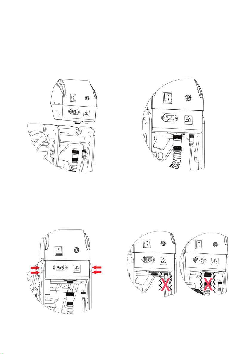
1. Assemble The Control Box
1.1 Take out control box inside of the
packing carton, then put the control box
on top of the machine in the right
position.
1.2 Fasten the control box onto the
machine with 4 screws tightly.
1.3 Connect 5 phase aviation plug and 2
phase aviation plug,then fasten tightly.
ATTENTION: The aviation plug must be
connected tightly.
CAUTION : A sway connector will cause
aviation plug burning under heavy
electricity.
www.proworldinc.com

2. Connecting the System
2.1 Connect the power cord into a
properly grounded electrical outlet with
a sucient amperage rating.
2.2 VOLTAGE: 120 Volt – The GS-601
requires a full 20 amp grounded circuit
for 120 volt operation. 240 Volt –The
GS-601 requires a full 10 amp grounded
circuit for 240 volt operation.
2.3 EXTENSION CORDS If used, should
be as short as possible and not less than
12 gauge.Heavy duty cords are
recommended.
2.4 CIRCUITS that have less than 15
amps or that have other high demand
equipment or appliances(especially more
than one heat seal machine) plugged in,
should not be used.
CAUTION: Failure to follow these
instructions will cause:
1. Erratic controller functions.
2. Inaccurate displays & slow heat-up.
3. The circuit breaker to disengage.
NOTE: If the supply cord is damaged, it
must be replaced by the manufacturer,
its service agent or a similarly qualied
person in order to avoid hazard.
3. Change To Auto Mode/Manual Mode
3.1 Turn around “Ramspin”system into
picture position, machine works under
automatic mode. Once close the
machine,electromagnet works to hold
machine closed. Once time is counting
down to zero,machine will auto open.
3.2 Turn the “Ramspin”system into
picture position,machine works under
manual mode. Once close the machine,
electromagnet does not work to hold
machine closed. Once time is counting
down to 0, machine needs to be opened
by hand.
Control Panel Guide

4.1 Switch The System On
4. Turn On The System
5.1 Press the Mode Select button located
in the center of the Control Panel.“Set
Temp” lights located in the display will
illuminate indicating you are in the adjust
temperature mode.
5. Adjusting The Temperature
5.2 Next, press the (-) button located to
the bottom of the Mode Select button to
lower the temperature setting,or press the
(+) button located to top of the Mode
Select button to raise the temperature
setting.The temperature can be set from
170° F (76° C) to 430° F (220° C).
6. Adjusting The Time
6.1 Once you have adjusted the
temperature, press the Mode Select button
again. “Set Time” lights located in the
display will illuminate indicating you are in
the adjust time mode.
6.2 Next, press the (-) button located to the
bottom of the Mode Select button to lower
the value ,or press the (+) button located
to top of the Mode Select button to raise
the time value .The time setting range can
be set from 0~999.
7. Adjusting The Time
7.1 Once you have get your target Temp.,
press the “SET” button again. “Set Time”
lights located in the display will illuminate.
8. Counter Setting
8.1 Once you have adjusted the time, press
the Mode Select button again. “Counter”
lights located in the display will illuminate
indicating you are in the counter setting
mode.
8.2 Next, press the (-) button to lower the
value ,or press the (+) button to raise the
value .The counter setting range can be set
from 0~999.
0~999.

9. Adjusting Pressure
9.1 First, locate the LED Display on the
Press.The Pressure Adjustment Knob is
located in the center of the heat platen.
9.2 To adjust the Pressure, simply turn the
Pressure Adjustment Knob to the right or
clockwise to increase the Pressure and to
the left or counter clockwise to decrease
the Pressure. The readout will display the
Pressure when locked down in the print
position.
9.3 A visual Pressure Readout is located on
the lower right side of the LCD Display.
When the handle is locked into the Print
Position, a pressure number will be
displayed. Readout will be on a scale of 0 -
9.A 0 Pressure readout would indicate no
pressure at all and 9 would indicate very
heavy pressure.
10. Printing & Pressing
• Once your equipment has reached the
designated temperature;
• Position the garment and application and
proceed to press;
• Lower and lock the heat platen into the
press position. This procedure will start the
automatic timing process;
• The timer will automatically count down
and lift the heat platen into the “UP”
position when the press cycle is complete;
NOTE: Please be aware after time is
complete, gas shocks will automatically
release the platen into the “UP” position.
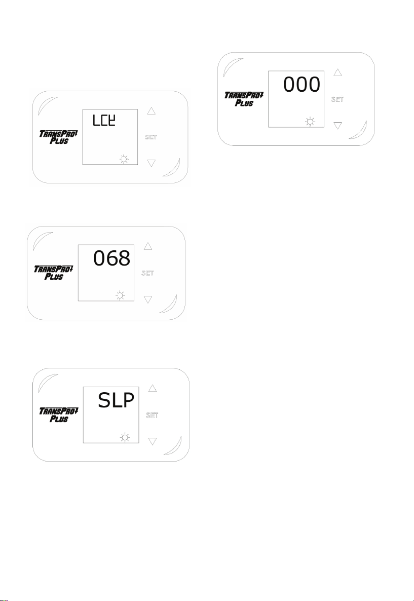
11. Switching Between F/C
11.1 Press “set” button for 4 seconds,
display shows LCK
11.2 Input 68 then press “set” button to
enter into second level menu.

11.3 Press “set” button to select “ctr” mode,
press up and down button to set value at 0
or 1, 0 for celsius, 1 for Fahrenheit
11.4 Press “set” button 4 seconds to quit.
12. Temperature Calibration
12.1 Press “set” button for 4 seconds,
display shows LCK
12.2 Input 68 then press “set” button to
enter into second level menu.
12.3 Press “set” button to select “Pb” mode.
Press up and down button to make tem-
perature calibration.
12.4 Press “set” button 4 seconds to quit.
Note:
If temperature on heat platen is
higher than circuit board shows,pls raise
the Pb value.
Example:
Heat platen temperature:190C
Circuit board temperature:185C
Pls set Pb Value at (+5)
13. Switching Between F/C
13.1 Press “set” button for 4 seconds,
display shows LCK
13.2 Input 68 then press “set” button to
enter into second level menu.
13.3 Press “set” button to select “Pb” mode.
Press up and down button to make tem-
perature calibration.
13.4 Press “set” button 4 seconds to quit.

Technical Parameters
Model: MP354 & MP350-1620
Heater Size: 16’’ 20’’ (406 508mm)
Pressure Display:Yes
Auto Open:Yes
Slide-out Lower Platen:Yes
Power(120volt) 1800W/16.4Amps
Power(240volt) 1800W/8.2Amps
Temperature Range:Max.221 /430
Heating Up Time(180 )20minutes
Time Range:0~999S
Way To Change Lower Platen: “Ramlock” quick change system
Machine Size (open size):29.5 x16.9 x39.3in
Packing Size:33.1 x20.5 x23.4 in
Packing Weight:119.0lbs
Certificate:CE,FCC

Technical Parameters Cont.
Part Name(English) Part No. Qty.
Display overlay 1600549 1
Control box top 1200446 1
Circuit breaker 15A 1800160 1
On/off switch 1800346 1
Emergency stop button 1200579 1
socket 1800344 1
Triac 1800586 1
Cooing sheet 1300672 1
Terminal Block 1800345 1
Circuit Board 1800353 1
Magnet switch 1800620 1
Magent 1800609 1
Control box base 1200685 1
16 5 phase aviation plug
(Female) with wires
welded
1800955 1
17 2 phase aviation plug
!Female"#with wires
welded
1800962 1
18 Machine handle 1200581 2
Machine handle 1200395 2
19 Machine arm 1200583 2
Machine arm 1200409 2
20 Washer 20-13-15 2000296 2
21 Lift links 1200140 2
Lift links 1200139 2
23 Machine body 1200582 2
Machine body 1200397 2
24 Supporting block 1200043 3
25 Rubber foot 1800317 4
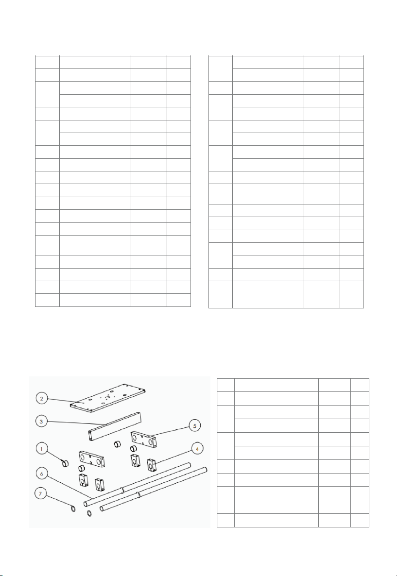
Technical Parameters Cont.
No. Part Name(English) Part No. Qty.
1 Cooper bush 1200075 4
2 Sliding Lower Platen Base 1200425 1
Sliding Lower Platen Base 1200426 1
3 Supporting Block 1200197 1
Supporting Block 1200052 1
4 Bearing block 1200648 4
5 Plated bar fixed board 1200044 2
6 Plated bar 1200411 2
Plated bar 1701037 2
7 O shape washer 1200309 4
Sliding System
26 Machine foot 1200649 2
27 1200051 1
28 Bridle links 1200138 2
Bridle links 1200218 2
29 Lower platen holding base 1200230 1
30 Gas spring 270N 1800054 2
Gas spring 350N 1800055 2
31 Position block 1200264 2
32 Threaded Pin 13-164 1200050 1
33 Threaded Pin 12-89 1200074 1
34 Handle shaft 1200145 1
35 Foam Grip 1200645 1
36 Screw M8*16 1901071 1
37 Adjustment spindle base 1800142 1
38 Adjustment
spindle(female)
1901072 1
39 Adjustment spindle(male) 1901073 1
40 Thermocouple 1800281 1
42 Balance screw 1901074 1
43 Thermosat 1800133 1
44 Lower platen 1800802 1
Lower platen 1800388 1
45 Adjustment knob 1800479 1
46 Silicon pad 1800422 1
Silicon pad 1200539 1
47 Platen holding block 1200068 1
Platen holding block 1200042 1
48 Heat platen 15*15 1200287 1
Heat platen 16*20 1800386 1
49 Electromagnet 600N 1200963 1
Electromagnet holding
sheet
1200067 1
51 Rubber foot 1200605 1
52 Holding sheet 1200045 1
53 Holding sheet screw 1200659 1
55 Heat platen cover 15*15 1200449 1
Heat platen cover 16*20 1200450 1
56 PP tube 1800835 1
57 5 phase aviation
plug(Male) with wires
welded
1800954 1

No. Part Name(English) Part No. Qty.
1 Ramlock base 1200958 1
2 Ramlock locking sheet 1200960 1
3 Ramlock locking set(male) 1200961 1
4 Ramlock locking screw 1900959 1
5 Ramlock handle 1200956 1
6 Ramlock locking set(female) 1200957 1
Technical Parameters Cont.
Ramlock System

WIRING SCHEMATIC
www.proworldinc.com

TRANSPRO WARRANTY
Warranty Coverage
TransPro products offered by Pro World are warranted against defects in material
and workmanship. Warranty is void if equipment has been damaged by accident,
unreasonable use, neglect, unauthorized and/or improper service, or other causes
not arising out of defects in material and workmanship. This warranty does not cover
damage caused by normal wear and tear, neglect or lack of proper maintenance.
This warranty is for the original purchaser/owner only, it is not transferable.
Warranty Duration
The heating element shall be warranted for the life of the heat press. There is a one
(1) year warranty on major components, circuit boards and all other components.
Warranty Performance
During the warranty period, and in the event that a situation cannot be resolved by
telephone/email and upon PRE-AUTHORIZATION from Pro World equipment must
be shipped, freight prepaid to Pro World for service in the original packaging. After
30 days, all shipping and insurance expenses to and from Pro World of in-warranty
equipment is solely the responsibility of the customer. Prior to 30 days the shipping
costs will be refunded if Pro World deems the equipment to be defective as stated.
Pro World cannot be held responsible for improper handling or any other damage
incurred in transit. No charge will be made for labor and components for repair of
in-warranty equipment. OUT-OF WARRANTY machines will be charged at the repair
rates in effect at the time the machine is received.
Warranty Disclaimers
Pro World shall not be liable for loss of use of TransPro equipment or other inciden-
tal or consequential costs, expenses, or damages incurred by the original purchaser
or any other user. The above warranty provisions constitute the entire agreement
between all parties, and supersede any and all prior written and/or oral representa-
tions and understandings.
This "Limited Warranty" applies to all TransPro equipment. However, the procedure
for obtaining service may vary outside the continental United States. Contact your
Pro World representative for warranty information. The purchaser is responsible for
compliance with all local laws, regulations and measure. Agreement shall be
governed by and construed in accordance with all applicable laws of said region.
www.proworldinc.com

www.ProWorldInc.com
Pro World Inc.
961 Bethel Ave.
Pennsauken, NJ 08110
Toll Free 800-678-8289
Outside U.S. 856-406-1020
Fax 856-406-1025
Table of contents
Other ProWorld Power Tools manuals

ProWorld
ProWorld TransPro Mug User manual

ProWorld
ProWorld TRANSPRO SEMI-AUTO CAP User manual

ProWorld
ProWorld TransPro Plus Mug User manual

ProWorld
ProWorld TransPro MP884 User manual

ProWorld
ProWorld TransPro Slide MP999 User manual

ProWorld
ProWorld TRANSPRO MINI User manual

ProWorld
ProWorld TransPro Plus Cap User manual
Popular Power Tools manuals by other brands


Scheppach
Scheppach HMS1070 Translation from the original instruction manual

Bosch
Bosch GSZ 160 Professional Original instructions

WERKZEUG
WERKZEUG 8057-WW quick start guide

Atlas
Atlas RIV 916 instruction manual

Parkside
Parkside PSTK 730 A1 Operation and safety notes

Craftsman
Craftsman 315.174921 owner's manual


