Muncie ADVANTAGE+ User manual

ADVANTAGE +
Service Manual - Rev 1


3
TABLE OF CONTENTS
HYDRAULIC
Hydraulic Specications ........................................................................................................................... 4
Port Designations ..................................................................................................................................... 5
Cartridge Designations, Functions, Part Numbers ................................................................................6-7
Hydraulic Schematic................................................................................................................................. 8
Explanation of Pressures.......................................................................................................................... 9
Solenoid Shift Sequence .......................................................................................................................... 9
Hydraulic Circuit Explanation.............................................................................................................10-14
Mechanical Locked Plow Conguration.................................................................................................. 15
Open Center to Closed Center Conversion............................................................................................ 16
Conguring for SA Telescopic Hoist Cylinders ....................................................................................... 17
Plow Pressure Release Manifold Iinstallation......................................................................................... 18
ELECTRICAL
System Wiring Assignments................................................................................................................... 19
System Block Diagram ........................................................................................................................... 20
Joystick Harness .................................................................................................................................... 21
Slave Harness ........................................................................................................................................ 22
Master / Slave Harness .......................................................................................................................... 23
Controller Errors ................................................................................................................................24-25
GENERAL
Glossary of Terms................................................................................................................................... 26
Troubleshooting Guide ......................................................................................................................27-29

4
HYDRAULIC SPECIFICATIONS
HYDRAULIC PRESSURE SETTINGS
FUNCTION DESIGNATION DEFAULT PSI* RANGE - PSI ADJUSTED
Main Relief TS3 2200 1500 - 3000 Electically
Clipper Relief RV2 1600 300 - 3500 Mechanically
Boost RV1 200 0 - 500 Mechanically
Spreader RV3 1600 300 - 3500 Mechanically
Plow Up RV5 2000 300 - 3500 Mechanically
Plow Down TS2 600 0 - 1000 Electically
Hoist Up RV4 2500 300 - 3500 Mechanically
Hoist Down TS1 600 0 - 1000 Electically
FUNCTION MAX FLOW RATES** DIFFERENTIAL PSI
Inlet Flow 50 GPM 200
Plow Up 15 GPM 200
Plow Down 23 GPM 200
Plow Angle 23 GPM 200
Hoist Up 32 GPM 200
Hoist Down 32 GPM 200
Spinner 15 GPM 200
Auger 15 GPM 200

5
HYDRAULIC PORT DESIGNATIONS
DESIGNATION FUNCTION SIZE (SAE)
PLA Plow Up 10
PLB Plow Down 10
P Pump 16
PAA Plow Left 10
PAB Plow Right 10
HB Hoist Down 12
A Auger 10
B Auger Reverse / Spreader Return 10
LS Load Sense 4
SSpinner 10
HA Hoist Up 12
Z* Route to Tank / Return Port* 16
*If manifold is congured for a SA telescopic hoist cylinder, connect this port directly to an open port on the reservoir. If manifold is
congured for a DA hoist cylinder, this port can be used as a return port.
PLA
AS
HA
B
HB
P
LS
Z
PAB
PAA
PLB

6
HYDRAULIC
CARTRIDGE DESIGNATIONS, FUNCTIONS, AND PART NUMBERS
EP4
CP2
CP3
CV6
FR1
SP3
SP2
RV4
SP5
RV3
CV9
OR4
EV1
TS3
RV1 CV10
ORF3
CV11
EH2
CV7 CV2
CB1
EH1
CB2
CV5 CV3
ORF1
PE2
TS2
SP1
CV4
CV1
EP2
RV5
SP6
SP4
TS1
CP1
CV8
EP3

7
DESIG PART NUMBER FUNCTION LOC. DESIG PART NUMBER FUNCTION LOC.
TS3 NXTS38-20AM-0-N-00 Main Relief Front EP2 NXEP16-S35-0-N-40 Compensator Top
TS1 NXTS12-36C-0-N-0 Hoist Downside Relief Top EP1 NXEP10-S35-0-N-10 Compensator Right
TS2 TS10-36C-0-N-0 Plow Downside Relief Right EP3 NXEP10-S35-0-N-10 Compensator Top
SP4 NXSP16-20M-0-N-00 Hoist Raise Top EP4 NXEP10-S35-0-N-10 Compensator Top
SP5 NXSP16-20M-0-N-00 Hoist Lower Top EH1 NXEHPR98-T33-0-N-12ER Plow Right Pilot Ctrl Front
SP6 NXSP12-20M-0-N-00 Plow Lower Top EH2 NXEHPR98-T33-0-N-12ER Plow Left Pilot Ctrl Front
SP2 NXSP10-20AM-0-N-00 Auger Top CV6 NXCV16-20-0-n-05 Hoist Load Hold Check Left
SP3 NXSP10-20M-0-N-00 Spinner Top CV8 NXCV10-20-0-N-15 Spreader Check Top
SP1 NXSP10-20M-0-N-00 Plow Raise Right CV9 NXCV10-20-0-N-15 Spreader Check Front
RV5 NXRV10-22A-0 Plow Raise Relief Top CV1 NXCV10-20-0-N-05 Check Valve Top
RV4 RV10-22A-0-NC-05-02 Hoist Raise Relief Top CV2 NXCV06-B20-0-5 Load Sense Check Front
RV3 RV10-22A-0-N-35-XX Spreader Relief Top CV3 NXCV06-B20-0-5 Load Sense Check Front
RV2 RV10-22A-0-N-35-XX Clipper Relief Front CV4 NXCV08-B20-0-4 Load Sense Check Front
RV1 NXRV08-20A-0-NC-05-02 Boost Pressure Relief Front CV5 NXCV08-B20-0-4 Load Sense Check Front
OR1 NX6101025 Orifice Front CV7 NXCV08-B20-0-4 Load Sense Check Front
OR2 NX6101025 Orifice Front CV10 NXCV08-B20-0-4 Load Sense Check Front
OR3 NX6101025 Orifice Front CV11 NXCV08-B20-0-4 Load Sense Check Front
OR4 NX6101025 Orifice Front CP3 NX6103116 Hoist Isolation Cavity Left
PE2 NXPE16-S67K-0-N Plow Angle Spool Right CP2 NXCP16-20-N Hoist Lower Check Top
CL1 4303712 Coil CP1 NXCP12-4L-N Aug Rev Cavity Plug Top
FR1 FR08-20F-0-N-/ 0.20 LS Drain Cartridge Left CB1 NXCBEA-LAN Plow Lt Counterbalance Front
EV1 NXEV16-S34-0-N-10 Unloader Front CB2 NXCBEA-LAN Plow Rt Counterbalance Front
HYDRAULIC
CARTRIDGE DESIGNATIONS, FUNCTIONS, AND PART NUMBERS

8

9
EXLANATION OF PRESSURES
HYDRAULIC
Pump PSI – The pump pressure Indicates the inlet pressure from the pump. This pressure will always be
approximately 200 PSI higher than the load sense pressure. This pressure will never exceed the main relief setting.
Load Sense PSI – The Load Sense PSI indicates the pressure communicated from the hydraulic load. With no
functions operating, the LS pressure should be 0 PSI. There will only be a LS pressure if a function is operating.
Boost / Differential Pressure – The boost or differential (pressure) is the difference between the Pump and the
Load Sense Pressures. Typical load sense hydraulic systems require a boost between 200 and 300 PSI. The boost
pressure is required to overcome the pressure drop across the valves. Using a gear pump, the boost pressure is
set using the boost pressure cartridge. Using a Piston Pump, the boost pressure is adjusted at the pump.
SOLENOID SHIFT SEQUENCE
Spinner TS3, SP2
Auger TS3, SP3
Plow Raise TS3, SP1
Plow Lower (DA) TS3, SP6, TS2
Plow Lower (SA) SP6
Plow Left TS3, EHPR2
Plow Right TS3, EHPR1
Dump Raise TS3, SP2
Dump Lower (DA) TS3, SP5, TS1
Dump Lower (SA) SP5

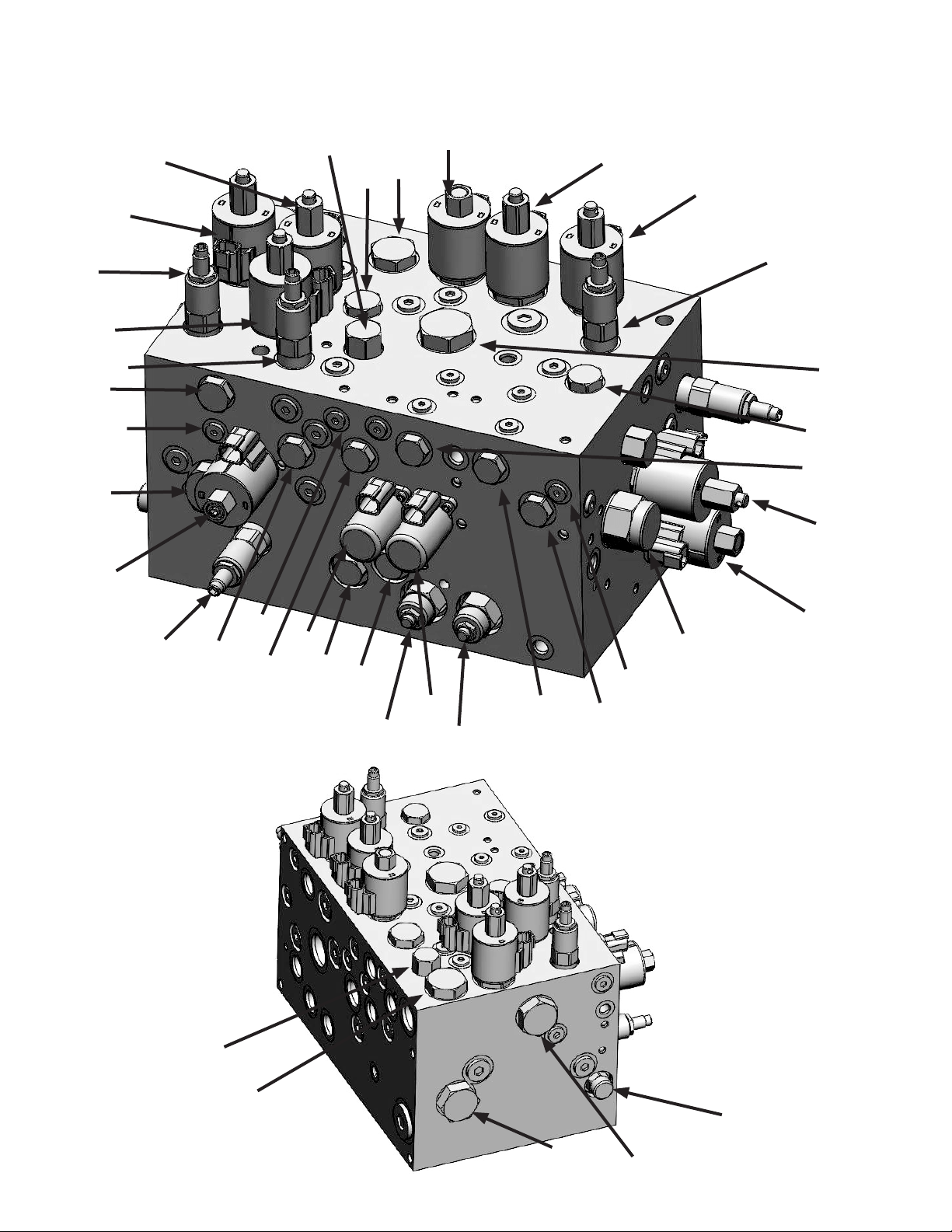
Pump Gage Port (PGP) – Indicates the inlet pressure from the pump. This pressure will be approximately 200 to 300
PSI higher than the Load Sense pressure.
Load Sense (LS2) – Indicates the pressure of the load. If more than one function is operating, the higher load pressure
will be observed. There will only be a pressure from the LS port if a function is operating. Remember, the Pump Gauge
will display a pressure approximately 200 PSI higher than the LS Gauge while a function is operating.
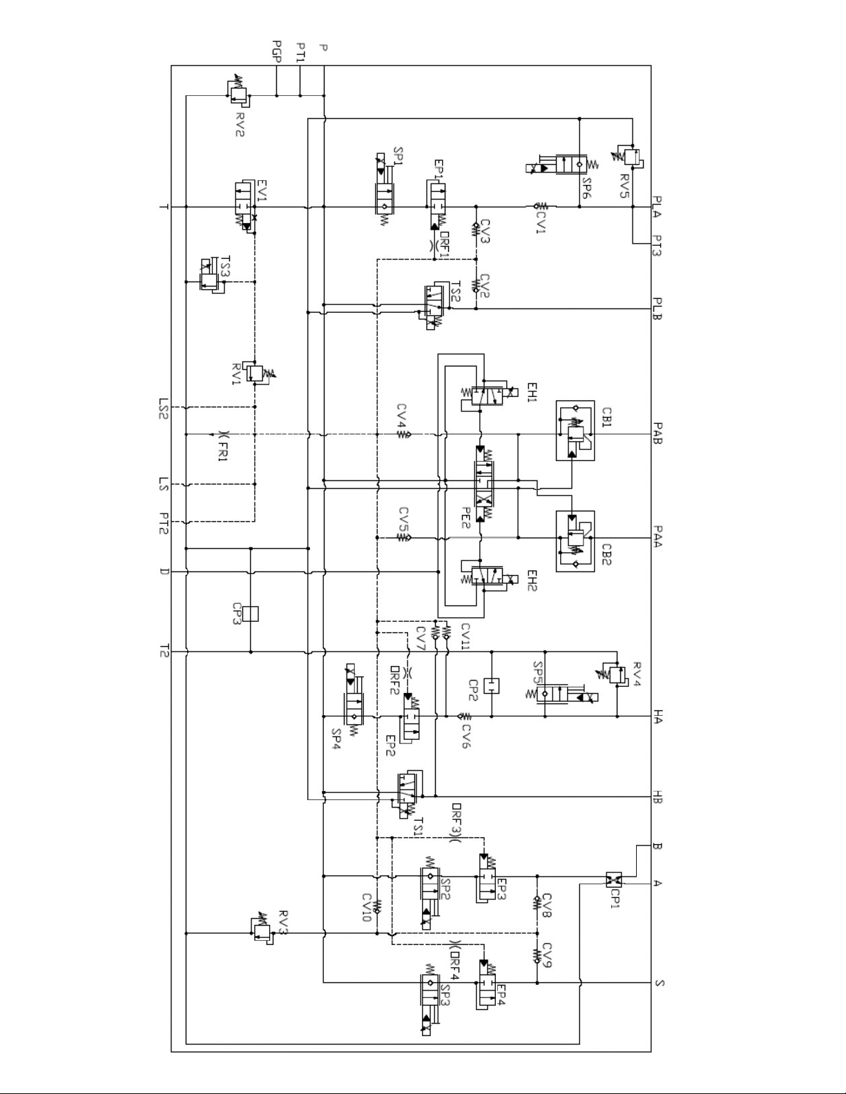
EV1 (Plugged when used with a piston pump) – unloading pressure compensating cartridge. EV1 is a normally closed
-two position - two way -pilot cartridge. It can provide a low pressure path for pump ow to escape to tank. This is its
primary function when the pump is bypassing (no functions operating). The bypass pressure of the pump in this state
will vary from about 20-60 PSI depending upon the pump ow. This pressure will show at PGP. The path to tank is
opened by pump pressure being applied to the left side pilot of EV1 which forces the valve open. The right side pilot
line of EV1 is drained to tank through the TS3 when not engaged (Electrically Actuated Main Relief Valve) to allow the
EV1 valve to open fully.
TS3 – Electrically Actuated Main Relief Valve. TS3 is a normally open two position - two way solenoid operated relief
valve. When its solenoid is not energized it provides a drain path for the pilot pressure on the right side of EV1. This
allows for pilot pressure on the left side of EV1 to push it open and expose a low pressure path for the pump ow to
escape to tank.
TS3 - will energize whenever any function of the Advantage Plus is operating. This closes the pilot drain on the right
side of EV1 and that in-turn causes EV1 to begin shutting off the pump ow escape to tank. Pump ow is now forced to
move toward the actuators as required. If TS3 was energized by itself or manually overridden without any other system
valves functioning, the pressure at PGP would be approximately 200 PSI to 300 PSI. The L.S. port would not show
pressure.
In addition, the TS3 valve is used as the main relief. It is an electrically adjustable relief that can be adjusted up to a
maximum setting of 3000 PSI.
RV1 (Plugged when used with a piston pump) – Boost Pressure Relief Valve. RV1’s purpose is to raise the
differential or boost pressure between PGP and LS by a margin of approximately 200 to 300 PSI. It comes into
play when TS1 is energized. At that point the pilot pressure on the right side of EV1 can only drain through RV1.
RV1’s internal bias spring is set for 200 PSI. That means the pressure of EV1’s pilots (both sides) must build to at
least 200 PSI before the right side pilot can drain through RV1 and allow EV1 to begin to open. This boost pressure
is required to allow ow to get through other cartridge valves in the system to operate functions.
When RV1 has a load-sense pressure applied to its right side, which is communicated from the array of LS check
valves (CV2, CV3, CV4, CV5, CV7, CV11, etc) this will add to the pressure required for EV1 to drain its right side
pilot and open. For example, if the load-sense pressure for a spreader motor is 1000 PSI, this will be added to the
(200 PSI) spring bias pressure of RV1. Now EV1 cannot begin to open its path to tank until the pump pressure has
achieved something slightly higher than 1200 PSI. PGP would display 1200 PSI and L.S. port would display 1000
PSI. In this way the system will always attempt to sustain a differential or boost pressure of approximately 200 PSI.
FR1– Load sense drain orice. FR1 provides a controlled drain for the load-sense pilot line. Its function is to
ensure that the pressure cannot be trapped in this pilot and result in EV1 not being able to fully open at low
pressure when required.
Post Compensators (EP1, EP2, EP3, and EP4) – The post compensators ensure that all functions will operate
simultaneously during low pump ow situations (when the circuit requires more oil than the pump can provide).
The pilots of the post compensators are directly tied to the LS pressure network. Each compensator will modulate
ow by restricting or allowing ow to pass to achieve a constant differential. This differential across all of the
compensators allows all of the functions to work with each other to prevent any one function from coming to a
complete stop.
RV2 – Clipper Relief – The purpose of this valve is to provide redundant pressure protection and clip any pressure
spikes that occur due to load shocks. Therefore, when a shock load occurs within the system, this relief will clip
any pressure beyond its set point.
10
EXPLANATION OF UNLOADING CIRCUIT
HYDRAULIC

11
EXPLANATION OF SPREADER CIRCUIT
HYDRAULIC
Proportional Valve (SP3) – Spinner ow control valve. SP3 is a proportional solenoid ow control valve.
In its un-energized state it provides a blocked path between the pump ow and the spinner work port. When it is
energized it provides an increasing orice opening to ow as a result of increasing electric current to its solenoid coil.
Proportional Valve (SP2) – Auger/Conveyor ow control valve. SP2 is a proportional solenoid ow control valve. In its
non-energized state it provides a blocked path between the pump ow and the auger/conveyor work port. When it is
energized it provides an increasing orice opening to ow as a result of increasing electric current to its solenoid coil.
Relief Valve (RV3) – Spreader Pressure Relief. RV3 limits the pressure of the spreader motor circuits. It is located in
the pilot load-sense line of the spreader work ports. It ultimately limits the pressure at the RV1 and therefore EV1 which
opens to dump pump ow to tank. RV3 is adjustable. Its pressure setting will be displayed at the LSGP if a spreader
motor load exceeds the relief setting or a blockage of a spreader work port occurs.
CV8 & CV9 – CV8 and CV9 are back-to-back check valves. Their purpose is to communicate the higher of the two
spreader motor pressures of the hoist circuit back to the RV1 boost pressure relief.
CP1 – Auger Reverse Cavity – This cavity can be populated with a solenoid actuated, 2 position / 2 way cartridge to
reverse the auger ow.

12
EXPLANATION OF PLOW CIRCUIT
HYDRAULIC
PE2 – Plow Angle Directional Control Valve – PE2 has a neutral position and two actuated positions. The actuated
positions alternately switch the tank and pressure lines connected to the cylinders to provide opposing angle directions.
This valve is known as a motor spool, therefore in its normal position it blocks the pump ow from passing. However, it
allows the pressure from the counterbalance valves to drain back to tank.
Plow Angle Pilot Controls – EH1 and EH2 – Pilot pressure control valves. EH1 and EH2 are solenoid operated pilot
valves. Their purpose is to provide hydraulic pilot shifting force to move the PE2 spool that in turn provide directional
control of the plow angle. When an EH valve is energized it completes a path from the pump to the end of the PE
directional control. Two EH valves are used for each PE valve. One actuates the PE to angle left and the other actuates
the PE spool to angle right. The EH valves use very little to no ow since they are pilot controls. When the EH valves
are not energized they drain any residual pressure from the actuation ends of the PE valves.
Plow Angle CounterbalanceValves – CB1 and CB2. The plow angle counterbalance valves provide several functions.
First, they provide crossover relief or cushion control for the plow angle cylinders. They prevent the circuit from being
damaged by shock loads. At 2750 PSI, they will relieve pressure and drain to tank. In addition, they are zero leakage
valves that prevent any sort of induced backpressure to unintentionally elevate the LS pressure network. These valves
are piloted open when the directional control shifts.
CV4 and CV5 – Check Valves – These valves allow the LS signal from the plow angle circuit to be relayed back to the
RV1. However, they prevent the LS signal from back feeding. They only allow oil to travel in one direction.
Plow Raise Flow Control (SP1) – SP1 is an electrically actuated proportional two position / two way valve. During its
non-energized state, it blocks pump ow from reaching the plow lift cylinder. When energized, it provides an increasing
orice opening to ow as a result of increasing electric current to its solenoid coil. When this valve opens, it allows oil
to ow from the pump to the cap side of the cylinder.
Plow Lower Flow Control (SP6) – SP6 is an electrically actuated proportional two position / two way valve. During
its non-energized state, it blocks the oil from draining from the cap end of the cylinder back to tank. When energized, it
provides an increasing orice opening to ow as a result of increasing electric current to its solenoid coil.

13
EXPLANATION OF PLOW DOWN CIRCUIT
HYDRAULIC
Plow Down Relief – The TS2 valve is a two position / three way proportional pressure valve. It serves multiple functions.
In its non-energized state, it provides a constant 100 PSI of down force on the rod side of the cylinder. When the plow
is raising, the oil from the rod side of the cylinder is drained back through this valve.
This valve is energized when lowering a DA cylinder. Its purpose is to provide an adjustable pressure to the rod-side of
the cylinder. The pressure setting of this valve is adjustable as a function of electrical current.
RV5 – Upside Pressure Relief – This is an adjustable relief valve that protects the cap side of the plow cylinder. This
is set at the factory at 2000 PSI. The valve will only open if the pressure at the cylinder reaches 2000 PSI.
CV1 – Load Holding Check – The purpose of CV1 is to hold the plow in the up position after oil has passed through the
SP1 cartridge. It will not allow oil to back feedback through the SP1.
CV3 & CV2 – CV3 and CV2 are back-to-back check valves. Their purpose is to communicate load sense pressures of
the plow circuit back to the RV1 boost pressure relief.
EXPLANATION OF PLOW DOWN CIRCUIT
SP4 – Hoist Raise Flow Control – SP4 is an electrically actuated proportional two position / two way valve. During its
non-energized state, it blocks pump ow from reaching the hoist cylinder. When energized, it provides an increasing
orice opening to ow as a result of increasing electric current to its solenoid coil. Its function is to raise the hoist. When
this valve opens, it allows oil to ow from the pump to the cap side of the cylinder.
SP5 – Hoist Lower Flow Control – SP5 is an electrically actuated proportional two position / two way valve. Its
function is to lower the hoist. During its non-energized state, it blocks the oil from draining from the cap end of the
cylinder back to tank. When energized, it provides an increasing orice opening to ow as a result of increasing electric
current to its solenoid coil.
RV4 - Upside Hoist Pressure Relief – This is an adjustable relief valve that protects the cap side of the Hoist cylinder.
This is set at the factory at 2500 PSI. The only time it will allow oil to drain back to tank is if the pressure reaches
2500 PSI.

14
EXPLANATION OF HOIST DOWN CIRCUIT
HYDRAULIC
Hoist Down Relief – The TS1 valve is a two position / three way proportional pressure valve. It serves multiple
functions. In its non-energized state, it provides a constant 100 PSI of down force on the rod side of the hoist cylinder.
When the hoist is raising, the oil from the rod side of the cylinder is drained back through this valve.
This valve is energized when lowering a DA hoist cylinder. Its purpose is to provide an adjustable pressure / down
force to the rod-side of the cylinder. The pressure setting of this valve is adjustable as a function of electrical current
(Maximum setting = 1000 PSI).
CP2 – Provisional Cavity – This cavity can be used to populate another SP valve in order to achieve faster hoist lower
speeds.
CV7 and CV11 – CV7 and CV11 are back-to-back check valves. Their purpose is to communicate the higher of the two
hoist pressures back to the RV1 boost pressure relief.
CV6– Hoist Shuttle Cartridge – Load Holding Check – The purpose of this valve is to hold the hoist suspended in the
air after oil has passed through the SP4.

15
HYDRAULIC
Mechanically Locked Plow
To allow the plow angle to free wheel for a mechanically locked plow, perform the following:
1. Locate CB1 and CB2 valves shown above
2. Loosen the lock-nut and use the appropriate Allen to turn both stems fully CW. This will take the pressure setting from
2750 PSI to 200 PSI.
3. Tighten the lock-nut
HYDRAULIC CONFIGURATIONS
CB1 CB2

16
HYDRAULIC
CONFIGURING SYSTEM FROM OPEN TO CLOSED CENTER
Instructions:
1. Locate the RV1 cavity and remove (Hydraforce P/N: RV08-20A-0-NC-05-02)
2. Replace with NXCP08-20-N
3. Within the control panel conguration menu:
a. Locate the Pump Type Selection in the Global Settings Menu
b. Toggle the box and change from gear to piston pump
RV1

17
HYDRAULIC
CONFIGURING SYSTEM FROM SA TELESCOPIC TO DA HOIST
Instructions:
1. Locate the CP2 cavity and remove (Hydraforce P/N: CP16-20N)
2. Locate the CP3 cavity, and reinstall the CP16-20N cartridge removed in step 1.
3. Install an SP16-20 into the CP2 cavity (SP16-20M-0-N-12ER)
4. Verify that the conguration le has been set for a “SA telescopic hoist cylinder”
5. Plug the appropriate electrical output into the newly installed SP16-20 (Wire Color Orange)*
The additional electrical hoist output will be a part of the standard wire harness even if unused. We will coil this
additional output if unused.
CP2
CP3

18
QUICK DISCONNECT ANGLE RT
QUICK DISCONNECT ANGLE LT PAA - ANGLE LT
PAB - ANGLE RT
TANK
HYDRAULIC
PLOW PRESSURE RELEASE MANIFOLD INSTALLATION
Purpose: This manifold is intended to relieve pressure within the plow angle lines. It allows easier connection
between quick disconnect ttings.
Operation Instruction: Pull actuators to relieve pressure within the plow angle circuit
Installation Instructions:
1. Locate the T Port – Route back to tank
2. Locate the PAA Port – Route to the PAA port on the Main Hydraulic Manifold
3. Locate the PAB Port – Route to the PAB port on the Main Hydraulic Manifold
4. Locate the PAA1 Port – Route to the plow left cylinder
5. Locate the PAB1 Port – Route to the plow right cylinder

19
Power / CAN - Gray Harness - Route into Cab
Black - Connect to Battery Ground
Red - Connect to 12VDC Battery
Yellow - Connect to 12VDC Ignition
Pink - Connect to Speedometer Input
Orange - Connect to Pre-Wet
ELECTRICAL GUIDE
WIRING ASSIGNMENTS
Gray Jacketed Cable – This cable supplies the controller with power, ground, and CAN connection.
Red Wire – Connect to 12VDC (Battery) with a 20A fused connection.
Yellow Wire – Ignition Power: Connect to a fused ignition power source.
Black Wire – Connect to Battery Ground
Pink Wire: – Connect to Speedometer Input
Orange Wire (When applicable): – Connect to pre-wet valve or pump (Source Current)

20
ELECTRICAL GUIDE
BLOCK DIAGRAM
Other manuals for ADVANTAGE+
2
Table of contents
Other Muncie Industrial Equipment manuals
Popular Industrial Equipment manuals by other brands

Afag
Afag UG 20 Series Translation of the Original Montage Instructions

Voyantic
Voyantic Tagsurance 3 manual

Siemens
Siemens SIMATIC MV230 operating instructions

Tecno Piu
Tecno Piu PTO 10/350 instruction manual

molex
molex RAST 5.0 instruction manual

Dupont
Dupont IntegraTec Ultrafiltration T-Rack Manifold II P... Assembly instructions