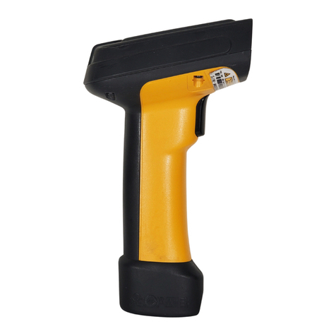
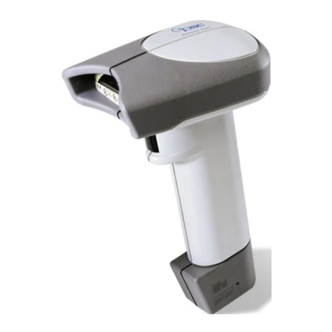
PSC SP400 Operating instructions

H
ANDHELD
L
ASER
S
CANNER
P
ROGRAMMING
G
UIDE
© 1999 PSC INC.R44-1020 (Rev. K) 1/03
SP400 Programming Guide
Asia Pacific
PSC Hong Kong
Hong Kong
Telephone: [852]-2-584-6210
Telefax: [852]-2-521-0291
Australia
PSC Asia Pacific Pty Ltd.
North Ryde, Australia
Telephone: [61]0(2)9878 8999
Telefax: [61]0(2)9878 8688
France
PSC Sarl
LES ULIS Cedex, France
Telephone: [33].01.64.86.71.00
Telefax : [33].01.64 46.72.44
Germany
PSC GmbH
Darmstadt, Germany
Telephone: + 49 (0) 61 51/93 58 - 0
Telefax: + 49 (0) 61 51/93 58 58
Italy
PSC S.r.l.
Vimercate (MI), Italy
Telephone: 039/62903.1
Telefax: 039/6859496
Japan
PSC Japan K.K.
Shinagawa-ku, Tokyo, Japan
Telephone: 81 (0)3 3491 6761
Telefax: 81 (0)3 3491 6656
Latin America
PSC S.A., INC.
Miami, Florida, USA
Telephone: (305) 539-0111
Telefax: (305) 539-0206
United Kingdom
PSC Bar Code Ltd.
Watford, England
Telephone: 44 (0) 1923 809500
Telefax: 44 (0) 1923 809 505
PRINTED WITH
SOY INK
Eugene Site
959 Terry Street
Eugene, OR 97402-9150
Telephone: (541) 683-5700
Toll Free: (800) 547-2507
Fax: (541) 686-1702
Corporate Headquarters
675 Basket Road
Webster, NY 14580-9787
Telephone: (716) 265-1600
Toll Free: (800) 828-6489
Telefax: (716) 265-6400
www.pscnet.com
Printed on recycled paper

PSC INC.
959 Terry Street
Eugene, Oregon 97402-9120
Telephone: (541) 683-5700
Toll Free: (800) 547-2507
Telefax: (541) 686-1702
PSC and the PSC logo are registered trademarks of PSC INC .
This manual and the procedures described in it are copyrighted, with all rights
reserved. Under copyright law, this manual may not be copied in whole or part
withoutprior writtenconsent fromPSC. The sameproprietary andcopyright notice
mustappearonanypermittedcopiesasappearsontheoriginal. Thisexceptiondoes
notpermitcopies tobemadeforothers,whetherornotsold. Underthelaw,copying
includes translating into another language or format including electronic media.
Disclaimer
Reasonable measures have been taken to ensure that all information contained
in this manual is complete and accurate. However, PSC reserves the right to
change any specification at any time without prior notice.

Contents
Introduction................................................................... 1
Reading the Interface Codes.......................................... 2
Changing Interfaces................................................. 4
Customizing Your Scanner Operation...................... 5
Programming Overview
What Is Programming Mode? ................................. 6
How To Program Using Barcodes............................ 6
Scanner Response When In Programming Mode.... 7
Return to Factory Settings....................................... 7
Where To Go From Here.......................................... 8
Interface Selection
IBM468x Port 5B ........................................................... 9
468x/9x Port 9B..................................................... 10
468x Port17........................................................... 11
469x Port E............................................................ 12
OCIA
Spectra-Physics..................................................... 13
NCR Eight-Bit (Short Format) ................................ 13
NCR Nine-Bit (Long Format).................................. 13
SNI ........................................................................ 13
Metrologic ............................................................. 13
Multidrop..................................................................... 14
Wand Emulation .......................................................... 15
Six-Bit
Omron ................................................................... 16
Fujitsu.................................................................... 16
Clover/Fujitsu......................................................... 16
Hugin Sweda ......................................................... 16
R44-1020 i

RS-232 ........................................................................ 17
Baud Rate .............................................................. 18
Data Format Settings ............................................. 19
Handshaking.......................................................... 20
UPC Data Format ................................................... 21
EAN Data Format ................................................... 22
Host Echo .............................................................. 22
Intercharacter Delay............................................... 23
Prefix & Suffix ....................................................... 25
Symbology Specific Identifiers .............................. 31
PC Keyboard Wedge.................................................... 37
Interface Selection................................................. 38
Connect to PC........................................................ 39
Intercharacter Delay............................................... 40
Prefix & Suffix ....................................................... 42
Symbology Specific Identifiers .............................. 48
Symbologies
Symbology Options Overview...................................... 56
Symbology Selection................................................... 58
UPC/EAN Options ........................................................ 61
Code 39 Options.......................................................... 64
Interleaved 2 of 5......................................................... 66
Standard 2 of 5............................................................ 70
Codabar Options.......................................................... 74
General Features
Audible Signal Settings................................................ 82
Read Verification ......................................................... 84
ii
SP400
Programming Guide

Appendix A — Standard Factory Default Settings
IBM 468x Port 5B ........................................................ 87
IBM 468x/9x Port 9B ................................................... 89
IBM 468x Port 17 ........................................................ 91
IBM 469x Port E .......................................................... 93
OCIA, PSC ................................................................... 95
OCIA, NCR Eight Bit..................................................... 97
OCIA, NCR Nine Bit...................................................... 98
OCIA, SNI .................................................................... 99
OCIA, Metrologic ....................................................... 101
Wand Emulation ........................................................ 103
RS-232 ...................................................................... 105
Keyboard Wedge ....................................................... 108
Six-Bit, Omron........................................................... 111
Six-Bit, Fujitsu ........................................................... 113
Six-Bit, Clover/Fujitsu ................................................ 115
Six-Bit, Hugin Sweda................................................. 117
Multidrop................................................................... 119
Appendix B — Additional Information
Host Programming .................................................... 120
Multi-Function Labels ................................................ 120
Appendix C — Test Barcodes
R44-1020 iii


R44-1020 1
GENERAL
INFORMATION
INTRODUCTION
This manual contains instructions for changing interfaces, barcodes for
customizing the scanner's operation and listings of the standard factory
settings for each standard interface. The organization is intended to
support a variety of users while making it quick and easy to find the
information you need. Look at the descriptions that follow to find where
to go from here.
I NEED TO UNDERSTAND THE BASICS
If you do not regularly use barcode labels to configure (program) scan-
ners, it will be very helpful to read the introductory portions of this
manual prior to beginning your programming session. In addition to the
information that follows, information of specific interest to you is titled:
— Programming Overview
— What is Programming Mode?
— How to Program Using Barcodes
— Scanner Response When in Programming Mode
— Where to Go From Here
I REGULARLY INTEGRATE PERIPHERALS INTO HOST SYSTEM
It is important that you understand that, although you can physically
attach all the various SP400 interface cables to your scanner, the scanner
must contain software that supports a specific interface in order to use that
interface. Therefore, the first step is to review the information that
immediately follows this introduction titled Reading the Interface Codes. It
shows how to identify which model scanner you have, lists these scanner
model numbers and shows the interface(s) supported by each model. Use
this information to verify that the model scanner that you purchased
supports the interface you wish to enable.
Next, turn to Appendix A, Standard Factory Settings, which contains
complete listings of each interface's factory configuration and shows how
to verify that your scanner contains this configuration. Assuming that your
scanner is configured using the standard factory settings, use this list to
identify any changes or additions you need to make.
Then, locate the programming labels you need and change the necessary
settings. Once you have completed these steps, you can begin scanning.
2
SP400
Programming Guide
GENERAL
INFORMATION
READING THE INTERFACE CODES
Before describing how to actually program your scanner, understanding
some of the information contained in the model number will help you to
understand the contents of the table on following page. The interface
code contained in the model number coincides with the table on the
following page which shows what interfaces are supported by the model
you have purchased.
The figure below shows where to find the model number label and which
digits are the Interface Code.
MODEL:
SERIAL NO:
MANUFACTURED:
180901-501000
xxxxxxxxx
month day, year
-501
Interface Code
(see chart)

INTERFACE(S) AVAILABLE
INTERFACE KEYBOARD RS-232 UNDECODED WAND
CODE 6-BIT IBM 46XX MDL OCIA WEDGE (STANDARD)(STANDARD)EMULATION
1001X
1012X
1023X
1034X
1045X
1058(INTERMEC)
1069TTL
10710 TTL(INVERTED)
10811 X
1096X
1107X
2013XX
2024XX
2032XX
2042XX
2053XX
2063XX
2073XX
2084XX
2094X X
2105XX
21111 X X
21211 X X
21311 X X
2146XX
2156XX
2166XX
2176X X
2186XX
2197XX
2207XX
2217XX
2227XX
3013XXX
3023XXX
3033XXX
3044XXX
3054XXX
3062XXX
3073XX X
3083XX X
3093XXX
3104XXX
31111 XXX
31211 XXX
31311 XXX
3146XXX
3156XXX
3166XX X
3176XX X
3186XXX
3196XXX
3206XX X
3216XXX
3226XX X
3236XX X
3247XXX
3257XXX
3267XXX
3277XX X
3287XXX
3297XXX
4013XXXX
4023XXXX
4033X XXX
4044X XXX
4053XX XX
40611 XXXX
4076X XXX
4086XXXX
4096XXXX
4106XXXX
4116XX XX
4126XX X X
4136X XXX
4146XX XX
4156XX X X
4166XX XX
4177XXXX
4187X XXX
4197XXXX
4207XXXX
5013X X XXX
5026X XXXX
5036XX XXX
5046XXXXX
5056XX XX X
5067X XXXX
5076XX XXX
6016XX XXXX
Factory Default Interfaces (on Power-up):
Indicates the active default interface software in the scanner when shipped.
1- Undecoded, standard 5- Wand Emulation 9- RS-232 TTL, standard
2- RS-232 6- Multidrop 10 - RS-232 TTL, inverted
3- OCIA 7- Keyboard Wedge 11 - Six-Bit
4- IBM 46xx 8- Undecoded, Intermec

4
SP400
Programming Guide
GENERAL
INFORMATION
0 01234 56789
CHANGING INTERFACES
Changing a scanner's interface is simply a
matter of changing the interface cable and
enabling the new interface. Once you have
changed interface cables and enabled the
new interface with the appropriate program-
ming label, the new interface becomes the
default interface that is active whenever
power is applied to the scanner.
NOTE
The SP400AR only supports undecoded,
RS-232 and Wand Emulation interfaces
ONLY.
Verify that your scanner supports the
interface you want to enable. The Interface
Code table indicates which interfaces your
scanner model supports. The following
steps describe the interface change proce-
dure.
1. Replace the interface cable that is
currently attached to the scanner
handle with an interface cable that
is for the new host system and
attach the scanner cable to the
proper port on your host.
2. Scan the interface barcode label that
is affixed to the new interface cable
or turn to the appropriate page in
this manual and scan the interface
enable programming label. This
will enable the software for the new
interface and disable the 'old'
interface software.
3. Scan a barcode to verify that the
scanner communicates correctly
with the host system. If any
changes to the scanner's factory
settings are needed, use the instruc-
tions titled, Customizing Your
Scanner Operation.

R44-1020 5
GENERAL
INFORMATION
CUSTOMIZING YOUR SCANNER OPERATION
Every time you change the active interface, a new set of factory settings
are enabled (refer to Appendix A, Standard Factory Settings, for a com-
plete list) and any changes that you want to make must be made to that
interface's factory settings. Previous changes made to other interface
settings are stored as that specific interface's configuration settings for
future use when you re-enable that interface. This allows the scanner to
retain a special configuration file for each interface.
Once you have changed cables and enabled the new interface, it may be
necessary to modify the standard factory settings to match your specific
host system's communication and symbology requirements. Check with
your system administrator to identify your host system's specific interface
requirements to ensure that they match the new interface you have
selected. Also, the scanner's operational features (e.g. speaker tone and
volume) can be customized to match your unique requirements.
1. Use the labels in this manual to modify the standard configu-
ration to match your specific interface requirements or user
preference.
2. Enable any additional symbologies as required and exit
Programming Mode.
3. Scan a regular barcode label and verify that the scanner and
host communicate correctly.
4. You have completed the factory settings change procedure.
If you change the interface again, these settings will be saved as the
default settings for this interface only.
If you experience difficulties, have ques-
tions or require additional information,
contact your local distributor or PSC
Customer Support Services at
1-800-547-2507.

6
SP400
Programming Guide
GENERAL
INFORMATION
PROGRAMMING OVERVIEW
This section describes how to set the scanner's programmable features.
These features can be configured using the barcode labels contained in
this manual or by using commands sent from the host. Refer to Appendix
B, Additional Information, for host programming details. If you program
the scanner using these barcodes, the scanner stores the changes until
reprogrammed. Whenever you use these labels to change programmable
features, you are changing these features for the active interface only.
WHAT ISPROGRAMMING MODE?
To change the scanner's programmed settings, it is necessary to place the
scanner in Programming Mode. This ensures that the scanner only
recognizes the special programming labels contained in this programming
guide.
HOW TOPROGRAM USING BARCODES
The following pages contain special barcode labels that are used to
change or enable the scanner's programmable options. All programming
sessions follow this order:
1. Scan the SET label at the top of the page. The scanner will
emit a low-to-high tone indicating it has read the label, and
will then begin flashing the green lamp. As long as the
scanner is flashing the green lamp, the scanner will only
recognize and decode programming labels.
2. Scan the feature label(s) for the programmable options
you wish to enable. The scanner will emit a low-to-high
tone each time you scan a valid label indicating it has read
and decoded the programming label. (All features are not
available for all interfaces.)
3. Scan the END label at the bottom of the page to complete
the programming session and exit Programming Mode.
You can scan any number of feature labels during a programming session
before scanning the END label, but you must scan the END label to save
changes and exit Programming Mode. The scanner will not exit Program-
ming Mode unless the END label is scanned. Disconnecting power during
Programming Mode, before scanning the END label, will cause the
scanner to forget any programming labels scanned during the current
programming session and will cause the scanner to return to its previous
settings.

R44-1020 7
GENERAL
INFORMATION
SCANNER RESPONSE WHEN INPROGRAMMING MODE
While in Programming Mode, the scanner will not decode regular barcode
labels and will only enable features supported by the currently active
interface. Maintaining a good record of all changes made for each
interface will help ensure that you know if the standard factory settings
have been changed.
Scanning regular barcode labels — the scanner will not read the
label and will not sound a tone.
Scanning a valid programming label —
a. If the feature is supported by the active interface, the
scanner will sound a low-to-high tone. This is the same
tone that sounds when you enter Programming Mode.
b. If the feature is not supported by the active interface, the
scanner will sound a long low tone. For example, if the
active interface is OCIA and you scan an RS-232 interface
parameter (e.g. Baud Rate = 9600), the scanner will sound
a long low tone.
IFYOU MAKE AMISTAKE...
If, during a programming session, you find that you are unsure of the
scanner's settings or wish to re-set the scanner's configuration, use the
Return to Factory Settings label on this page to return the scanner's
configuration to the factory settings. Scanning this label only affects the
interface that is currently active, and will reset any changes made to this
interface during a previous programming session.
Appendix A contains a complete list of all standard factory settings.
RETURN TO FACTORY SETTINGS
Scan this label to return the scanner to the factory settings for the active
interface.

8
SP400
Programming Guide
GENERAL
INFORMATION
WHERE TOGOFROM HERE
Programming is easy and straightforward if you follow these steps:
1. Turn to Appendix A and review the factory settings for the
interface you will be using.
2. Scan the interface enable barcode label if you are changing
interfaces.
3. Scan any feature labels that are unique to the interface you
are currently programming. These interface specific program-
ming labels immediately follow each interface selection label.
5. Turn to page 54 if you are going to change any barcode
symbologies or modify any symbology related features.
6. Turn to page 79 if you wish to change or modify any of the
scanner's general features.
Once the necessary changes have been made, and you have scanned the
END label, you are ready to scan.

R44-1020 9
DATA FORMAT
IBM 468XPORT 5B INTERFACE SELECTION
Scan this label to enable the IBM 468x Port 5B interface.
IBM 468XPORT 5B SETTINGS
Data Format: Send As Code 39 — converts barcode data (UPC-D, UPC/
EAN, add-ons, Code 93, Standard 2 of 5, Codabar, MSI/Plessey and Code
128) into Code 39 format before sending the data to the host.
These settings are for IBM 468x Port 5B interface ONLY.
SET -------------------------------------
SEND AS CODE 39 ------------
DON'TSEND AS CODE 39------
END -------------------------------------
Go to the sections titled Symbology Selection and General Features in the
back of this programming guide if you want to change any other factory
settings for this interface.
INTERFACE
IBM PORT 5B

10
SP400
Programming Guide
IBM 468X/9XPORT 9B INTERFACE SELECTION
Scan this label to enable the IBM 468x/9x Port 9B interface.
IBM 468X/9XPORT 9B SETTINGS
Data Format: Send As Code 39 — converts barcode data (UPC-D, UPC/
EAN, add-ons, Code 93, Standard 2 of 5, Codabar, MSI/Plessey and Code
128) into Code 39 format before sending the data to the host.
These settings are for IBM 468x/9x Port 9B interface ONLY.
SET -------------------------------------
SEND AS CODE 39 ------------
DON'TSEND AS CODE 39------
END -------------------------------------
Go to the sections titled Symbology Selection and General Features in the
back of this programming guide if you want to change any other factory
settings for this interface.
DATA FORMAT
INTERFACE
IBM PORT 9B

R44-1020 11
INTERFACE
IBM PORT 17
IBM 468XPORT 17 INTERFACE SELECTION
Scan this label to enable the IBM 468x Port 17 interface.
IBM 468XPORT 17 SETTINGS
Data Format: Send As Code 39 — converts barcode data (UPC-D, UPC/
EAN, add-ons, Code 93, Standard 2 of 5, Codabar, MSI/Plessey and Code
128) into Code 39 format before sending the data to the host.
These settings are for IBM 468x Port 17 interface ONLY.
SET -------------------------------------
SEND AS CODE 39 ------------
DON'TSEND AS CODE 39------
END -------------------------------------
Go to the sections titled Symbology Selection and General Features in the
back of this programming guide if you want to change any other factory
settings for this interface.
DATA FORMAT

12
SP400
Programming Guide
INTERFACE
IBM PORT E
IBM 468X/9XPORT E INTERFACE SELECTION
Scan this label to enable the IBM 468x/9x Port E interface.
IBM 468X/9XPORT E SETTINGS
Data Format: Send As Code 39 — converts barcode data (UPC-D, UPC/
EAN, add-ons, Code 93, Standard 2 of 5, Codabar, MSI/Plessey and Code
128) into Code 39 format before sending the data to the host.
These settings are for IBM 468x/9x Port E interface ONLY.
SET -------------------------------------
SEND AS CODE 39 ------------
DON'TSEND AS CODE 39------
END -------------------------------------
Go to the sections titled Symbology Selection and General Features in the
back of this programming guide if you want to change any other factory
settings for this interface.

R44-1020 13
PSC OCIA INTERFACE SELECTION
Scan this label to enable the Spectra-Physics OCIA interface.
NCR OCIA EIGHT BIT (SHORT FORMAT) INTERFACE SELECTION
Scan this label to enable the NCR OCIA (short format) interface.
NCR OCIA NINE BIT (LONG FORMAT) INTERFACE SELECTION
Scan this label to enable the NCR OCIA Nine Bit (long format) interface.
SNI OCIA INTERFACE SELECTION
Scan this label to enable the SNI OCIA interface.
METROLOGIC OCIA INTERFACE SELECTION
Scan this label to enable the Metrologic OCIA interface.
Go to the sections titled Symbology Selection and General Features in the
back of this programming guide if you want to change any other factory
settings for these interfaces.
INTERFACE
OCIA

14
SP400
Programming Guide
INTERFACE
MULTIDROP
MULTIDROP INTERFACE SELECTION
Scan the Enable Interface label to select multidrop as the active interface.
Your system configuration will determine which peripheral ID setting to
select.
MULTIDROP SETTINGS
SET -------------------------------------
ID = 70 ---------------------
ID = 71 ---------------------
ID = 72 ---------------------
ID = 73 ---------------------
END -------------------------------------
Go to the sections titled Symbology Selection and General Features in the
back of this programming guide if you want to change any other factory
settings for this interface.
SET PERIPHERAL ID
Other manuals for SP400
2
Table of contents
Other PSC Barcode Reader manuals

PSC
PSC Duet User manual

PSC
PSC vs1200 User manual

PSC
PSC QS200 Owner's manual

PSC
PSC HS1250, User manual

PSC
PSC FALCON 315 User manual

PSC
PSC Magellan 2300HS User manual

PSC
PSC magellan 8100 User manual

PSC
PSC PowerScan RF User guide

PSC
PSC LINEAR IMAGER 7000 Installation and operation manual

PSC
PSC Magellan 2200VS omega User manual

PSC
PSC SP400rf Operating instructions

PSC
PSC PowerScan RF User manual

PSC
PSC LM520 Owner's manual

PSC
PSC HS1250, User manual

PSC
PSC MAGELLAN 1000I User manual

PSC
PSC Scanners Operating instructions

PSC
PSC QuickScan QS2500 Installation and operation manual

PSC
PSC HD User manual

PSC
PSC Magellan 8500 User manual

PSC
PSC PSRF-1000 User guide