PSI AC 710 Manual


Manual Version: 2023/10
© PSI (Photon Systems Instruments), spol. s r.o.
www.psi.cz
This document and its parts can be copied or provided to a third party only with the express permission of PSI.
The contents of this manual have been verified to correspond to the specifications of the device. However, deviations cannot be ruled
out. Therefore, a complete correspondence between the manual and the real device cannot be guaranteed. The information in this
manual is regularly checked, and corrections may be made in subsequent versions.
The visualizations shown in this manual are only illustrative.
This manual is an integral part of the purchase and delivery of equipment and its accessories and both Parties must abide by it.

Page | 3
TABLE OF CONTENTS
1Warnings and Safety Precautions .......................................................................................................... 4
2General Description............................................................................................................................... 4
2.1 Cooling Unit AC 710 Equipment ...................................................................................................................4
3Installation ............................................................................................................................................ 5
4Warranty Conditions ............................................................................................................................. 7

Page | 4
1WARNINGS AND SAFETY PRECAUTIONS
PLEASE READ THE FOLLOWING INSTRUCTIONS CAREFULLY BEFORE SWITCHING ON THE COOLING UNIT AC 710!
GENERAL ELECTRICAL SAFETY GUIDELINES:
•Perform a routine check of the devices and their wiring.
•Replace worn or damaged cords immediately.
•Use appropriate electrical extension cords/power bars and do not overload them.
•Place the devices on a flat and firm surface. Keep them away from wet floors and counters.
•Avoid touching the device, socket outlet or switch if your hands are wet.
•Do not perform any alterations to the electrical part of the devices or their components.
The following table presents basic highlight symbols used in this manual:
Symbol
Description
Important information, read carefully.
Complementary and additional information.
2GENERAL DESCRIPTION
Additional Cooling Unit AC 710 is designed to regulate temperature of MC water bath in the extended range, down to 15 °C with the
resolution of ± 1 °C at standard laboratory conditions. This accessory device is also recommended for applications requiring high light
intensities as some heating of the water bath by the LEDs always occurs.
The Cooling Unit AC 710 is supplied in two versions –for 210-240 V AC and 110 V AC power line.
2.1 COOLING UNIT AC 710 EQUIPMENT
Cooling Unit AC 710 package consists of:
•AC 710 water pump (Fig. 1A)
•Hailea HC-130A water chiller
•one piece of power cable
•one piece of AUX cable
•one piece of elastic silicone tube 8/6 mm –5 m length
Page | 5
3INSTALLATION
Place the Cooling Unit AC 710 on a flat, firm and dry surface! Let it stand in upright position for at least 12 hours
before plugging it into power supply!
1. For a safe and proper operation of the AC 710 cooling kit, switch OFF the Multi-Cultivator MC 1000 device prior installing the Cooling
Unit AC 710.
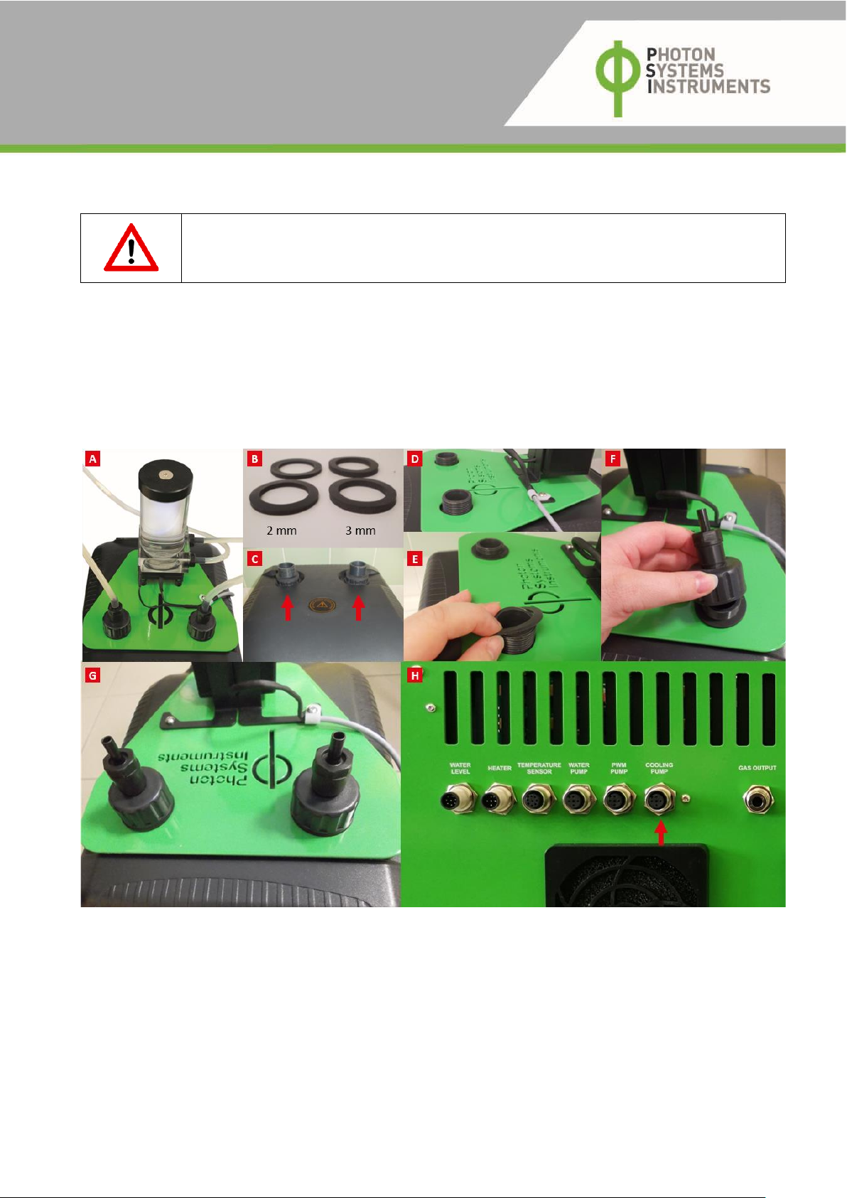
2. Connect the water pump with the water chiller (Fig. 1A) by placing two circular rubber seals (3 mm) around the outlets on the top of
the Hailea water chiller (Fig. 1B-C). Then, put the water pump on the top of the water chiller (Fig. 1D) and place the other two seals
(2 mm) around the outlets of Hailea water chiller (Fig. 1E). Finally, fix the water pump to the water chiller with screws (Fig. 1F-G).
3. Plug the AC 710 water pump connector into the cooling pump connector (AUX 1) output on the rear panel of the MC 1000-OD (Fig.
1H). This connection provides the powering of the pump as well as controls its function in remote mode (MC 1000-OD controls the
circulation of the water in water cooling circuit).
Fig. 1 A) AC 710 water pump. B) Four circular rubber seals. C) Water outlets on the top of the Hailea water chiller. D-H) Installation of the water pump
to the water chiller. G) Connection of the Cooling Unit AC 710 with the Multi-Cultivator using AUX cable.
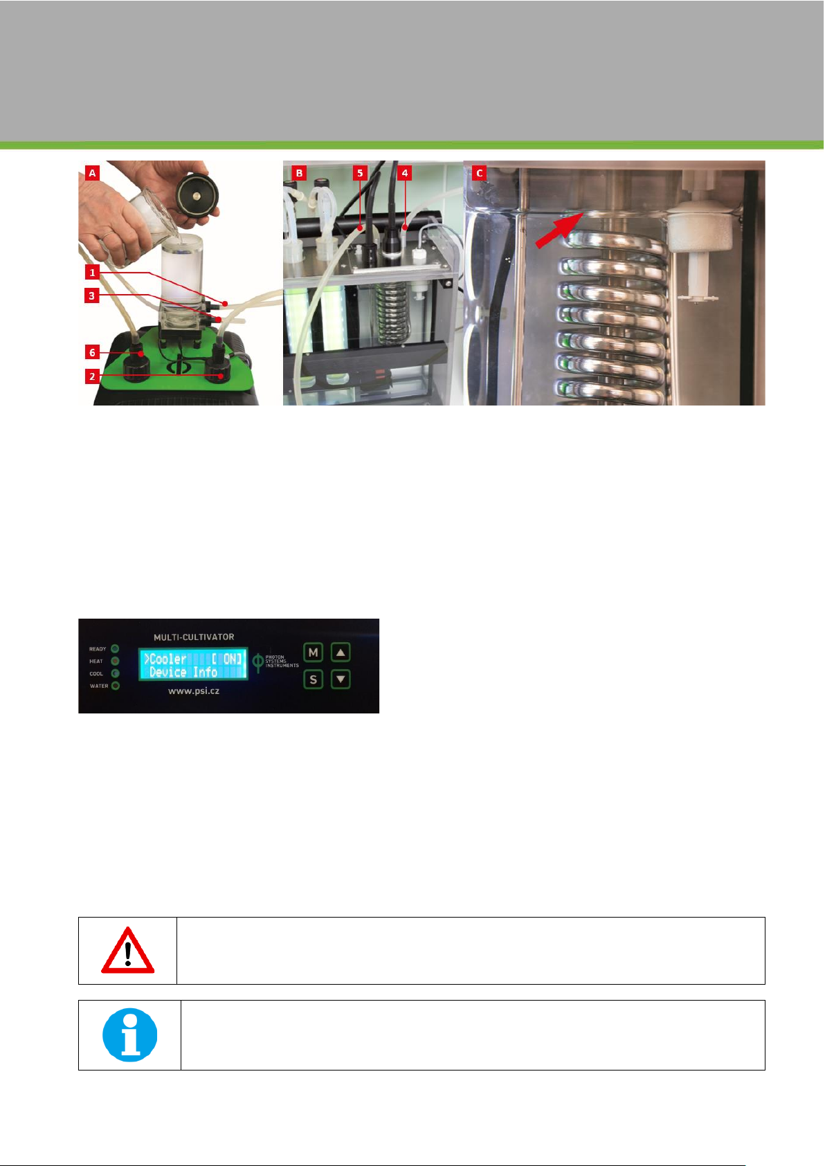
4. Inter-connect the AC 710 water pump, Hailea water chiller and MC 1000-OD cooling spiral using the water circulation hose (Fig. 2A-
B). First, attach ca. 1 m silicone hose to the lower port (Fig. 2A-3) of the water pump. Then connect the second end of this tubing to
the top input of the cooling spiral (Fig. 2B-4).
5. After that, connect the short, ca. 30 cm long silicone hose, to the upper port (Fig. 2A-1) of the water pump and inter-connect it with
the top input of the water chiller (Fig. 2A-2).
6. Finally, use the ca. 1 m long silicone hose to connect the other output of the MC 1000-OD cooling spiral (Fig. 2B-5) with the Hailea
water chiller (Fig. 2A-6).
Page | 6
Fig. 2 A) Filling of the water pump with distilled water + Connection of the water pump with the Hailea water chiller. B) Connection of the Cooling Unit
with the MC 1000-OD. C) Optimal water level in the MC 1000-OD water bath.
7. Plug the Hailea water chiller in AC electricity.
8. Switch ON the Hailea water chiller using main power button on its side. Front display shows the actual temperature in the small
water tank positioned inside of the Hailea water chiller. Please read the attached Hailea HC-130A manual for more information.
9. Switch ON the MC 1000-OD device. Fill the MC 1000-OD water bath with distilled water while the water level in water bath is sufficient
(Fig. 2C).
10. Unscrew the top cover of the AC 710 water pump reservoir and fill it with water (Fig. 2A).
11. Switch ON the cooling pump via MC front control display: Settings > Cooler > ON (Fig. 3). The active pump circulates the cold water
in the water-cooling circuit and stops automatically after 2 minutes. The cooler function is used to fill the water-cooling circuit with
water or to get rid of air bubbles in the hoses. The active water pump is indicated by a lit LED that illuminates the reservoir.
Fig. 3 MC 1000-OD front control display: Cooler ON.
12. While the pump is active, slowly add distilled water in the water pump reservoir (Fig. 2A) to fill the entire cooling system (tubing,
Hailea inner water tank, and MC cooling spiral) –ca 1 l of distilled water is needed.
13. The minimum water level in the pump reservoir must be above its upper port. Usually, the reservoir should be filled to 2/3 of its
volume.
14. Set the required temperature of the water in the Hailea water chiller to 5-10 °C: Long push the SET button on the Hailea front panel
>> change the blinking value to the required temperature using arrows >> press SET button.
15. Set the required MC cultivation temperature using MC front control display or PBR control software. When the Multi-Cultivator is
cooling, the blue LED light indicator COOL next to the Multi-Cultivator control display is lit.
16. MC 1000-OD is now set to control automatically the temperature in the water bath by circulating the cold water from the water
chiller into the MC cooling spiral that is immersed in the MC water bath. Regulation is provided by the MC 1000-OD automatically.
Check the water level in the cooling circuit regularly. When the water level drops to 50 % of the water pump
reservoir capacity, refill the reservoir.
It is recommended not to leave the tank without the water. However, running the pump without water will not
damage the Cooling Unit AC 710. The water pump is prevented from overheating as it will automatically switch
off if the pump temperature rises too high.

Page | 7
4WARRANTY CONDITIONS
1. Photon Systems Instruments, Ltd. (PSI) warrants all its instruments to be free from defects in materials or workmanship for a period
of one year from the date of invoice/shipment from PSI. Warranty term for the European Union member states is two years.
2. If at any time within this warranty period the instrument does not function as warranted, return it and PSI will repair or replace it at
no charge. The customer is responsible for shipping and insurance charges (for the full product value) to PSI. PSI is responsible for
shipping and insurance on return of the instrument to the customer.
3. No warranty will apply to any instrument that has been (i) modified, altered, or repaired by persons unauthorized by PSI; (ii) subjected
to misuse, negligence, or accident; (iii) connected, installed, adjusted, or used otherwise than in accordance with the instructions
supplied by PSI.
4. The warranty is return-to-base only, and does not include on-site repair charges such as labor, travel, or other expenses associated
with the repair or installation of replacement parts at the customer’s site.
5. PSI repairs or replaces the faulty instruments as quickly as possible; maximum time is one month.
6. PSI will keep spare parts or their adequate substitutes for a period of at least five years.
7. Returned instruments must be packaged sufficiently so as not to assume any transit damage. If damage is caused due to insufficient
packaging, the instrument will be treated as an out-of-warranty repair and charged as such.
8. PSI also offers out-of-warranty repairs. These are usually returned to the customer on a cash-on-delivery basis.
9. Wear & Tear Items are excluded from this warranty. The term Wear & Tear denotes the damage that naturally and inevitably occurs
as a result of normal use or aging even when an item is used competently and with care and proper maintenance.
10. Some PSI instruments use accessories made by other manufacturers. In such case, these accessories may be covered by a different
warranty period.
11. Contact us at [email protected] in case of any support with the assembly and installation of the device is needed.
Table of contents
Other PSI Laboratory Equipment manuals


Popular Laboratory Equipment manuals by other brands


OHAUS
OHAUS STORP1 General instructions

BioLAB
BioLAB BMRW-104 Operation manual

STERILUX
STERILUX SterOx System V Series Instructions for use

Orion Diagnostica
Orion Diagnostica QuikRead go CRP manual

Tecno-gaz
Tecno-gaz Europa B EVO Instructions for use

Blue-White industries
Blue-White industries C-600P manual