EYELA N-3100 User manual

TOKYO RIKAKIKAI CO., LTD
This instruction manual contains important information for maintaining the
product's functions and ensuring safe use.
Keep this manual close to the product so that you can easily access.
IMPORTANT In particular, be sure to read the "Safety
Precautions" carefully before use.
Instruction
Manual
R00
Model N-3100
Rotary
Vacuum Evaporator

Some parts of the main unit become hot due to the
functions and characteristics of this product and
which may cause unpredictable injury if you touch it
unintentionally during operation or work. In addition,
improper installation or piping may cause functional
decline or a failure.
However, knowing about the risks in advance will
help preventing most of the accidents.
1. Signal words
Although we have thoroughly considered the potential hazards in the product use, it is
extremely difficult to predict all hazards. Therefore, the precautions described in this
manual do not necessarily cover all hazards.
Nevertheless, following the instructions in this manual will help you operate the product
and work more safely. Always pay special attention to prevent accidents and product
failure when handling this product.
Alert Marks
Signal words Definition
WARNING
CAUTION
Safety Precautions
Therefore, this manual categorizes the level of
importance and danger as below with alert marks
and signal words.
Please follow the instructions and use the product
safely.
Mishandling the product will cause serious personal injury or
loss of life.
Mishandling the product may injure users or cause property
damage.

Caution and Warning labels are attached on the
product for the most important warning items.
The labels attached locations are as follows.
Pay special attention to the information of the
labels when using the product.
2. Warning display on the products
If the labels are worn out and hard to read the
descriptions, please contact us for replacement
labels.
运行本产品时,请勿
触摸样品瓶和水槽
注意
小心烫伤
16
16
Do not touch
evaporating flask and
bath while running the
product.
CAUTION
Hot surface
22
Fire hazard
Use high-temperature
heat medium and
exercise care when
setting temperature.
WARNING 22
谨防起火
请务必使用高温用
热媒,并注意设定
温度
警告
Do not touch the
clamp while the
sample flask is rotating.
Fear of injury
CAUTION
当样品瓶旋转时,
不要触摸夹具
注意
小心受伤

1 Guide for Safe Use・・・・・・・・・・・
2 Product Overview
2-1 Applications・・・・・・・・・・・・
2-2 Specifications ・・・・・・・・・・・
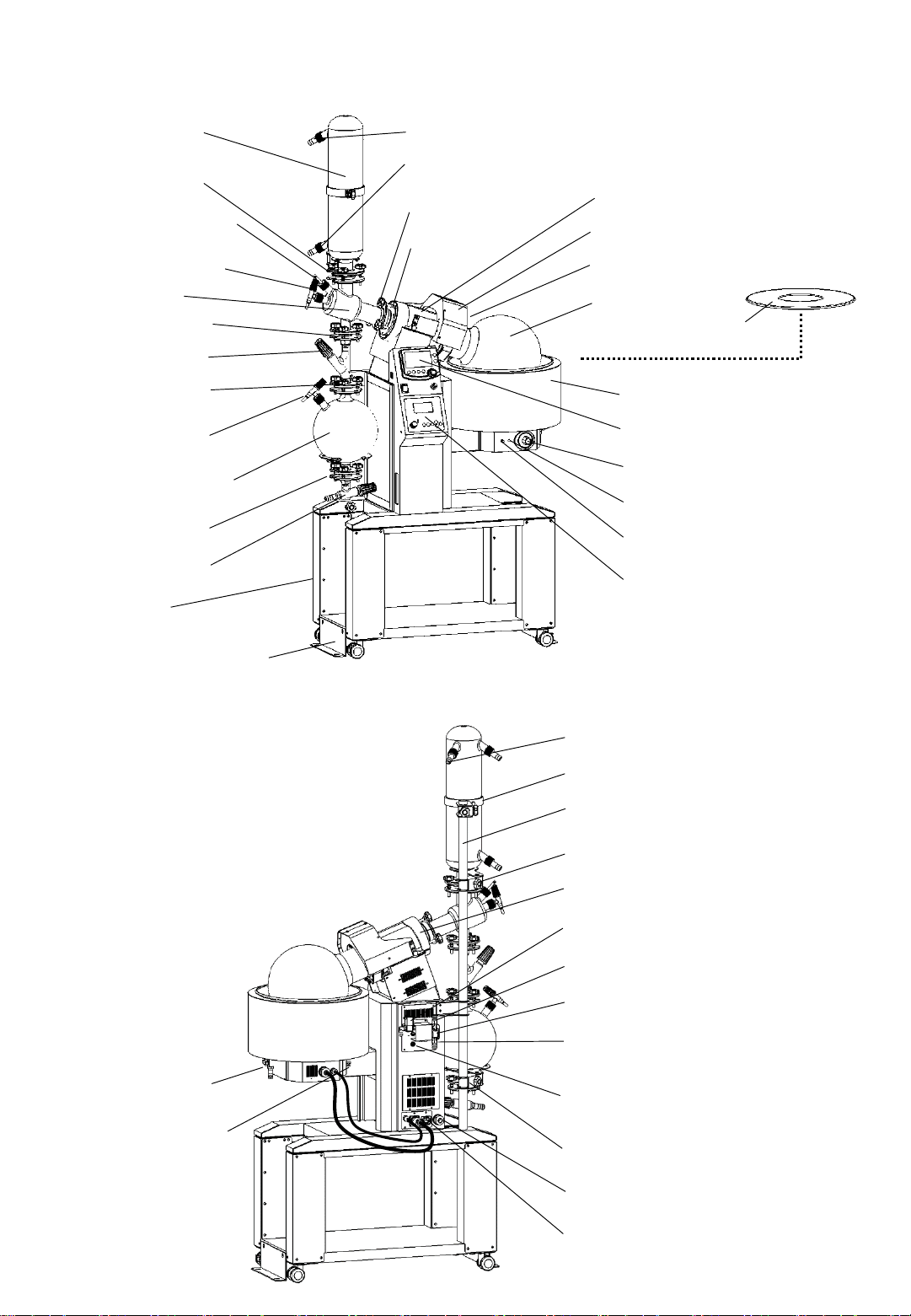
2-3 Descriptions・・・・・・・・・・・・
2-4 Control Modes・・・・・・・・・・・
3 Names and Functions of the Control Panel
3-1 Control Panel ・・・・・・・・・・・
3-2 Vacuum Control Unit Control
Panel ・・ ・・ ・・ ・・ ・・ ・・・
3-3 Main Unit Control Panel・・・・・・・
3-4 Main Unit Safety features and
Alarms ・・・ ・・ ・・ ・・ ・・・
3-5 Alarms and Warning Functions of the
Vacuum Control Unit Control
Panel ・・ ・・ ・・ ・・ ・・ ・・・
4 Installation
4-1 Installation Environment ・・・・・・
4-2 Installation Requirements ・・・・・・
4-3 Peripheral Devices ・・・・・・・・
4-4 Connecting the Utility・・・・・・・・
4-5 Precautions ・・・・・・・・・・・・
4-6 Assembling Glassware ・・・・・・・
5 Operation
5-1 Preparation・・・・・・・・・・・・・・・
5-2 How to Operate the Main Unit・・・・・・・
5-3 Alarm Functions of the Main Unit ・・・・・
5-4 Setting Functions of the Main Unit ・・・・・
5-5 How to Operate the Vacuum Control Unit ・・
5-6 MANUAL Mode Operation ・・・・・・・・
5-7 AUTO Mode ・・・・・・・・・・・・・・
5-8 PROGRAM Mode ・・・・・ ・・・・・・
5-9 STEP PROGRAM Mode ・・・・・・・・・
5-10 Linked Operation with the Operational Part of
the Main Unit ・・・・・・・・・・・・・
5-11 Setting the Parameters ・・・・・・・・・
5-12 Operation After Control ・・・・・・・・・
6 Troubleshooting・・・・・・・・・・・・・・・
7 Maintenance and Inspection
7-1 Cleaning ・・・・・・・・・・・・・・・・
7-2 Replacing the Fuse ・・・・・・・・・・・
7-3 Cleaning the Control Solenoid Valve ・・・・
7-4 Replacing the Vacuum Seal・・・・・・・・
8 Disposal・・・・・・・・・・・・・・・・・・
9 After-sales service ・・・・・・・・・・・・・
10 List of Consumable and Replacement Parts and
Optional Accessories・・・・・・・・・・・・
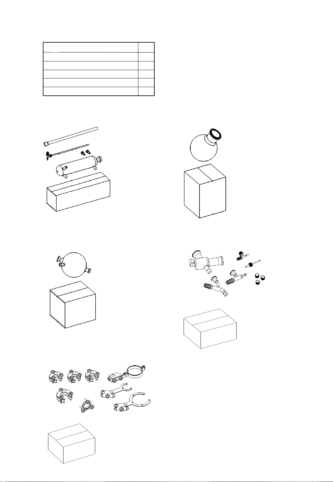
Be sure to check the type and quantity of parts
before installation.
In addition, prepare an appropriate vacuum pump
for depressurization, vacuum hose, cooling water
circulator, piping hose, cold trap, and etc.
Thank you for purchasing.
product.
This manual describes procedures for installation, operation, troubleshooting, maintenance, inspection,
and disposal of the
10L Scale Rotary Evaporator Model N-3100.
Please read this manual carefully and fully understand the contents before using the product.
Introduction
Contents
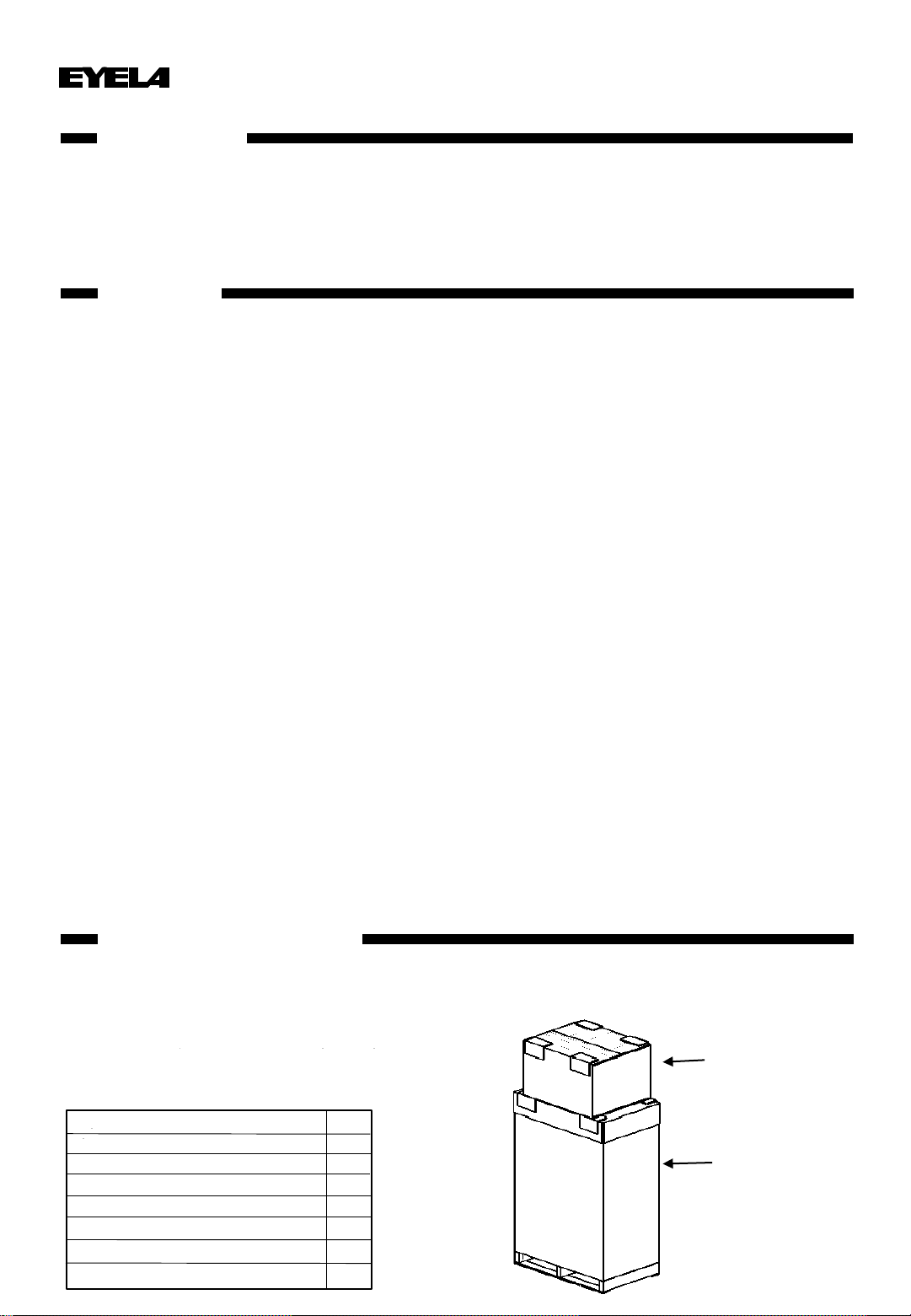
Contents of the package
Qty
Evaporator main unit 1 set
Stand pole 1
1
1
1
1
1) Main unit packing box
Instruction manual
Warranty card
Sample flask receiver 2
Fuse (2 A)
1
2
2
4
6
8
9
10
11
14
17
17
18
19
20
21
24
25
26
27
32
36
38
41
46
51
52
55
56
60
60
61
62
63
64
65
2) Box for glassware
1) Box for main unit
Spanner

2-1) Box for condenser 2-2) Box for sample flask
•Sample flask
2-3) Box for receiving flask
•Receiving flask
2-4) Box for adapter
2-5) Box for clamps
•Condenser
•Continuous injection valve
•Nozzle set (2 pcs)
•Vacuum hose (with a nozzle
on one side)
•Adapter
•Stop valve
•Drain valve
•Leak valve
•Bar thermometer
•GL25 Screw cap
(3 pcs, used as a spare
stopper for the threaded hole
of the receiving flask and
adapter)
•S40 clamp (3 pcs)
•S65 Clamp
•QVF50 Clamp
(QVF50 flange, QVF50 insert, QVF50 knob bolt (3 pcs))
•Cooler clamp
•Cooler support holder
•Receiving flask support holder
Qty
2-1) Box for condenser 1
2-2) Box for sample flask 1
1
1
2) Box for glassware
2-5) Box for clamps
2-3) Box for receiving flask 1
2-4) Box for adapter

Oil type
KF-96-30
KF-96-50
KF-96-100
KF-54
* Pay due attention to the amount of oil used because the oil is thermally expanded.
* Particularly hot areas ・Edge of the bath
・Top panel of the cover
Be sure to use specified high-temperature heating medium.
+150 to +170℃
+170 to +180℃
Water or oil can be used for this product, but when
using oil, be sure to use specified high-temperature
heating medium.
Use of other liquids which is not specified may result
in injury or burns.
In addition, the accuracy of the operating
temperature may not be obtained due to
stirrerd conditions.
* If water gets into the oil at a temperature of 100 °Cor higher, vapor is occured explosively,
causing the water and oil to splash violently. When using the product at a temperature of
100°C or more, pay special attention to prevent water being mixed into the oil.
* The recommended oil is not a guarantee of safety. Pay attention to ventilate the roomwhile
using the oil.
Temperature control range
+80 to +120℃
+120 to +150℃
Recommended oil, Made by Shin-Etsu Chemical Co., Ltd
Especially when using the oil at high temperature, the liquid may splash up and may
burn your hands depending on the rotation speed of the flask.
Pay attention to the flask rotation speed when the liquid temperature is high.
When using silicone oil after using water, dry the water thoroughly before adding the
silicone oil.
Do not touch the clamp section during operation or
shortly after stopping rotation.
The uneven shape of the clamp or the protruding part
of the locking pin may cause injury.
Do not move the main unit when the liquid temperature is high.
Do not touch the clamp while the flask is rotating.
Do not place any objects under the bath arm.
The liquid temperature in the bath is high during and
after use. If the main body is moved, the liquid may splash
and burn your hands.
Do not place anyobjects or put your arm between the bottom of
the bath arm and base of the main unit. Otherwise, this may
result in injury.
-1 -
1 Guide for Safe Use
This product is not explosion-proof. Pay special attention to safety.
CAUTION
WARNING
・Cooking oil
・Machine oil
CAUTION
CAUTION
CAUTION
CAUTION

Product Overview2
-2 -
2-1 Applications
This product is a rotary evaporator capable of efficiently
concentrate, separate and dry reaction liquid, extracted
liquid, and etc. under reduced pressure, and recover
distillated liquid.
The vacuum pressure, bath temperature and cooling
water temperature differ depending on the intended use.
Prepare a cooling water circulator, vacuum pump and
cold trap that are suitable for the intended use.
* Although the parts used in this equipment are corrosion-
resistant, it doesn’t mean it’s resistant to all kinds of
solvents. Depending on the solvent and operating
conditions, the control valve and pressure sensor may be
deteriorated and result in loss of control.
If there are any such risks, a solvent recovery device
such as a cold trap must be installed between the rotary
evaporator and the vacuum control unit.
Teflon vacuum seal, pressure sensor and control valve
are consumable parts.
Since some adjustment works are required to replace the
pressure sensor, please contact your local dealer or
service center when you need it repaired.
2-2 Specifications
Do not modify the product.
Do not use the product for any purpose
other than its intended application.
Modification or use of the product for purposes other than its
intended use may result in electric shock or failure.
WARNING
RotaryVacuum Evaporator
N-3100
Rotation speed range 10 - 140rpm
Ultimate vacuum 2.6hPa (2 Torr or less)
Temperaturecontrol range Room temperature +10 °C to 180 °C (for water or oil)
± 1 °C (with water, when sample flask is rotating)
± 3 °C (with oil, when sample flask is rotating)
Temperature control
Microcontroller based PID control (Pt 100 Ω)
Rotation speed setting Set bythe control knob, digital display
Bathtemperature setting, display Set bythe sheet key, digital display
Lifting of the bath Electrical lift
Heater 3.5kW
Motor Induction motor 90 W (inverter controlled)
Sample flask 10 L Round-bottom flask (diameter: 100 mm)
Vacuum seal Teflon seal
Bath Inner size: dia360 × 200H mm, capacity: 20 L, material: SUS304
Jack stroke 150mm
Ambient temperature range +5 to +35 °C
930W x480 D x1890H mm, approx. 103 kg
17A(-18A)、3.9kVA(-4.3kVA), 230(-240VAC)single phase 50/60Hz
Condenser: cooling water nozzle OD 16mm, vacuum nozzle OD 16mm
Vacuum control solenoid valve: connection nozzle OD 13mm, leak valve: nozzle OD 10mm
Temperature control
accuracy
Function
Vacuum control
function
Condenser
5 L Round-bottom flask, with leak valve,
with drain valve (S40 ball joint,16 mm hose nozzle)
Stand-alone over-heat protector, Earth leakage circuit breaker,
Rotation slow start,Bath emptyheating protector, Overflow pipe,
Overload failure detector for the rotarymotor inverter unit
Set by sheet key, dial type
4 types of control mode: Fixed value, Auto, Slope program, Step program
Vertical triple-coil type, cooling area 0.5 m2(screw-type inlet/cooling
water connection port, S65 ball joint, 16 mm hose nozzle)
Power input, rated power supply
Overall dimensions(mm), weight
Product name
Model
Performance
Safetyfeatures
Receiving flask
Configuration
Connector size
Standard

-3 -
Performance
Pressure measuring range 0 - 1066 hPa (mbar) (0 - 106.6 kPa) (0 - 800 mmHg (Torr))
Pressure
setting
range
Manual control (fixed value
control) VAC, 1 - 1013 hPa (mbar) (VAC, 0 - 101.3 kPa) (VAC, 1 - 760 mmHg (Torr))
Auto control (automatic
control) Automatic pressure control and automatic fixed value pressure setting control
according to the samples
Program control (slope
control) Typical 55 solvents are pre-programmed. User can program other 10 solvents.
Step program control
Fixed value control: VAC, 1 –1013 hPa (mbar), Atmo,
(VAC, 0 –101.3 kPa, Atmo) (VAC, 1 –760 mmHg
(Torr), Atmo)
Slope control: 1 - 1013 hPa (mbar) (0.1 - 101.3 kPa) (1 - 760 mmHg (Torr))
Pressure displayed units hPa, kPa, mbar, mmHg, Torr
Hysteresis
setting range Fixed value control Auto (2 %) or 1 - 20 hPa (mbar) (0.1 - 2.0 kPa) (1 - 15 mmHg (Torr))
Slope control Auto (2 %) or 1 - 20 % *1
Vapor temperature measuring range 0 to +150 °C (when connected with optional sensor)
Time setting range [Automatic stop] OFF, 1 - 999 min, [Slope control] 1 - 999 min
[Step program control] 0 - 999 min
Pressure control mode 4 types of control mode: Fixed value control, Auto control, Solvent program
control, Step program control (99 steps, 5 programs)
Function
Setting Set by sheet key, dial type
Display items Operation mode, measured pressure value, set pressure value, vapor
temperature (with optional sensor), operating elapsed time, operation status
Automatic pressure release function Automatic pressure release at the end of control ON/OFF setting available.
Cleaning function Automatic cleaning at the end of operation (operation time 1 - 10 min setting)
ON/OFF setting available Manual cleaning: Long-press the Leak key
Hold function The vacuum pressure can be held at any level during the depressurization by
slope control.
Diaphragm vacuum pump control PID control
Configuration
Pressure sensor Diffused semiconductor pressure transducer, wetted part material: SUS316L
Solenoid valve for pressure release Orifice diameter: Ø 1.6 mm
Material of piping and joints PP, PTFE
Standard
Leakage nozzle size Ø 10 mm
Control solenoid valve Nozzle size Ø 13 mm, Orifice size Ø 3.2 mm, Material of the wetted parts of the
solenoid valve: PPS, PTFE
Recommended pump (optional) Diaphragm vacuum pump Model N950
Specifications of the vacuum control unit
*1 This is the percentage value of the slope target pressure value.

-4 -
2-3 Descriptions
1. Condenser
5. S65 Clamp
10. S40 Clamp
10. S40 Clamp
10. S40 Clamp
3. Cooling water connection port
14. Drain valve
11. Stop valve
12. Leak valve
7. Continuous
injection valve
6. Bar thermometer
8. Adapter
9. QVF50 Flange
21. One-touch clamp
23. Sample flask
13. Receiving flask 31. Variable overheat protector
Vacuum control unit control panel
33. Safety cover
27. Vacuum seal
25. Bath
22. Rack
Control panel for controlling bath
temperature and flask rotation
26. Rack fixing bracket
24. Sample flask receiver
Reset switch
power indicator light
4. Condenser Clamp
2. Vacuum connection port
15. Stand pole
28. Drain valve
29. Overflow port
18. Condenser support joint
20. Receiving flask support joint
17. Solenoid valve for pressure release
16. Solenoid valve for vacuum control
30. Power cable
Connection nozzle (from condenser)
Connection nozzle (to vacuum pump)
19. Vapor duct
32. AC outlet
(for vacuum pump output, 230 V, max. 2 A)
Drive section
34. Communication port for cooling water
circulator

No. Name
数量 No. Name 数量
1 Condenser 1 16
Solenoid valve for vacuum control (nozzle
diameter: 13 mm)
1
2
Vacuum connection port (PP nozzle diameter
16mm, GL25 threaded hole)
117
Solenoid valve for pressure release (nozzle
diameter: 10mm)
1
3
Cooling water connection port (PP nozzle
diameter 16mm, GL25 threaded hole)
218
Condenser support joint 1
4
Condenser clamp 1 19 Vapor duct *built-in 1
5
S65 Ball clamp 1 20 Receiving flask support joint 1
6
Bar thermometer (compatible with GL25
threaded hole)
121
One-touch clamps 1
22
Rack 1
23
Sample flask (10L) 1
8
Adapter 1 24 Sample flask receiver 1
9
QVF50 Flange 1 25 Bath 1set
10
S40 Ball Clamp 3 26 Rack fixing bracket 2
27
Vacuum seal 1
28
Drain valve (3/8 x Ø 17 mm nozzle) 1
29
Overflow port (1/4 x Ø 14 mm nozzle) 1
30
Power cable 1
13
Receiving flask (5L) 1 31
Variable overheat protector (variable range:
+50 to +250 °C)
1
32
*AC outlet (for vacuum pump N950) 1
33
Safety cover 1
15
Stand pole 1 34 Communication port for cooling water
circulator 1
7
Continuous injection valve (orifice diameter: 6
mm, nozzle diameter: 6 mm, spindle: PTFE,
compatible with GL25 thread end)
1
11
1
Stop valve
(Orifice diameter: 25 mm, spindle: PTFE)
12
Leak valve (orifice diameter: 6 mm, nozzle
diameter: 6 mm, spindle: PTFE, compatible with
GL25 thread end)
1
14
1
Drain valve (orifice diameter: 10 mm )
(Nozzle diameter: 16 mm, Spindle: PTFE)
-5 -
* AC outlet is connected to the power of optional diaphragm vacuum pump N950 by connecting cable(optional).
Fuse
(for AC outlet, 2 A)
Vapor sensor
connection port
Earth leakage
circuit breaker
Micro USB connector
(for PC communication)
Vacuum control unit
control panel
Control panel for bath
temperature and flask rotation

2-4 Control Modes
MANUAL mode (fixed value control)
The vacuum is controlled by the fixed pressure (Set
Press) after starting operation.
The setting range of the fixed pressure (Set Press) is
VAC (continuous depressurization) to 1013 hPa (760
mmHg).
The fixed pressure value can be changed regardless of
whether the equipment is in standby, depressurization
or fixed value control.
Automatic stop according to the operating time can be
performed by setting operation stop conditions (Auto
Stop).
There are four types of functions in the vacuum
control mode.
Set Press
Time
Auto Stop
Leak Menu
Run
Stop
Power
Mode
MANUAL Standby
00:00:00
Display
1013hPa
Set Press
hPa
100
Leak Menu
Run
Stop
Power
Pressure
Rotation 60rpm
Bath 40.0 ℃
AUTO mode (automatic control)
You can select from two types of automatic control modes:
AUTO mode and AUTO-2 mode.
AUTO mode automatically controls the pressure in order to
prevent bumping and automatically determines the pressure
(Mark Press) at which both recovery rate and concentration
time can be compatibly performed.
Automatic stop according to the operating time can be
performed by setting operation stop conditions (Auto Stop).
AUTO-2 mode requires optional vapor temperature sensor.
In addition to the functions of AUTO mode, the following
functions can be performed:
•Fixed pressure control at automatically determined
pressure (Mark Press) according to the vapor
temperature (Set Temp)
•Automatic stop due to temperature rise (Stop Temp)
over the vapor temperature (Set Temp)
•Able to accept mixed solvents by adjusting temperature
(Adjust Temp) and the number of adjusting time (Mark
Count).
•This mode is preset so that the optimal state is attained
when; the room temperature is 25 °C ±3 °C and the
cooling water temperature is 5 to 10 °C,
Low boiling point solvent, bath temperature 40 °C
High boiling point solvent, bath temperature 60 °C
•Bumping may be inevitable for some samples. In such a
case, try to reduce the volume of samples, reduce the
rotation speed of the sample flask or lower the bath
temperature. Time
Mark Press
Stop Temp
Vapor
temperature
Set Temp
Pressure
Time
Leak Menu
Run
Stop
Power
Mode
AUTO Standby
00:00:00
Display
1013hPa
Leak Menu
Run
Stop
Power
Mark Press
---- hPa
Rotation 60rpm
Bath 40.0 ℃
-6 -

STEP PROGRAM mode
PROGRAM mode (slope control)
In this mode, appropriate vacuum control according to the
solvent can be performed using a total of 65 solvents in the
database. The database is contained with the 10 solvents that
user can set arbitrarily and typical 55 solvents including pre-
programmed 10 solvents with appropriate settings.
The factory default solvents are as follows:
* The factory default settings are appropriate:
when the bath temperature is 40 °C, the cooling water
temperature is 5 to 10 °C and the room temperature is
25 °C ±3 °C.
Slope control by the slope time (Slope Time) is performed from
the slope starting pressure (Slope Point) to the fixed pressure
(Set Press) and then the vacuum pressure is controlled by the
fixed pressure.
Automatic stop by the operating time can be performed by
setting operation stop conditions (Auto Stop).
Up to 18 characters can be used for the user-registered
solvent name.
You can use alphanumeric characters, spaces and symbols
( ,. -+*/()).
There are 5 programs with up to 99 steps to be used
as a programmable vacuum controller. Fixed value
control, slope control and atmospheric vacuum release
can be programmed.
The vacuum pressure is controlled by the set pressure
(Press) and the step operation time (Time).
The following items can be set in the program
execution setting screen:
Start step number (Start Step No.)
Finish step number (Finish Step No.)
Number of repetitions (Repeat)
Automatic pressure relief (Auto Leak)
Automatic cleaning (Auto Cleaning)
Recovery from power failure (Power Fail)
2: Acetone (350 hPa → 240 hPa: 6 min)
7: Benzene (160 hPa → 90 hPa: 4 min)
13: Chloroform (380 hPa → 200 hPa: 6 min)
17: 1,2-Dichloroethane (180 hPa → 70hPa: 6 min)
21: Dichloromethane (950 hPa → 480 hPa: 6 min)
26: Diethyl ether (800 hPa → 550 hPa: 6 min)
30: Ethyl acetate (266 hPa → 93 hPa: 4 min)
35: Hexane (280 hPa → 160 hPa: 4 min)
52: Toluene (90 hPa → 20hPa: 8 min)
53: 1,1,1-Trichloroethane (340 hPa → 160 hPa: 6min)
Time
Slope Point
Set Press
Pressure
Slope Time
Auto Stop
Leak Menu
Run
Stop
Power
Mode
PROGRAM Standby
00:00:00
Display
1013hPa
Set Press
hPa
240
Leak Menu
Run
Stop
Power
Acetone
Leak Menu
Run
Stop
Power
Mode
STEP PROGRAM Standby
00:00:00
Display
1013hPa
Leak Menu
Run
Stop
Power
P No 1
REPEAT 0 / 1
Step No2
Time
Step No1
Step No3
Step No4
Step No5
Step No2 Step No3 Step No4 Step No5
Pressure
Rotation 60rpm
Bath 40.0 ℃
Rotation 60rpm
Bath 40.0 ℃
-7 -

3-1 Control Panel
Names and Functions of the Control Panel
3
-8 -
①Power switch
③Vacuum
control unit
control panel
②Bath lift switch
④Main unit
control panel
No Name Function
①Power switch Used to turn on the main unit.
②
Bath lift switch Used to move up/down the bath.
③
Vacuum control
unit control panel
Used to display and operate the vacuum control.
④
Main unit control
panel
Used to display and operate the bus temperature control and rotation control.

①
LCD display
Displays the control mode, set value, measured value and operation status.
②
Operation status
Displays operation status such as standby (Standby), running (Run), pressure release (Leak),
cleaning (Cleaning) or hold (Hold).
③
Pressure control status
Displays an arrow that indicates the pressure control status (depressurization,
depressurization slope, fixed value, pressure rise, pressure rise slope) during operation.
④
Measured pressure
Displays measured pressure value.
⑤
Operating time
Displays the operating time as “day
hour:minute:second”.
When the operation time is shorter than 24 hours, the day is not displayed.
⑥
Auto stop
When the automatic stop by operation time is set, the set time is displayed. This may be
adjusted automatically according to the operating status.
⑦
Mode
Displays the control mode "MANUAL", "AUTO", "PROGRAM" or "STEP PROGRAM".
⑧
Set pressure value
Displays the set pressure value.
⑨
Vapor temperature
Displays the measured vapor temperature when a vapor temperature sensor is connected.
⑩
Rotation speed
Displays the rotation speed of the rotating part of the main unit.
⑪
Bath temperature
Displays the measured temperature of the main bath.
⑫
Power key
Used to turn on the power of the vacuum control unit.
* During operation, the power key is invalid until the unit stops.
⑬
Run/Stop key
Used to start/stop operation (automatic pressure release, automatic cleaning) .
* The next operation is not accepted for approx. 2 seconds after the operation stop.
⑭
Leak key
Used to open/close the leak valve.
During operation: The leak valve will open while the key is pressed.
During stop: Press this key will open the leak valve, and press again will close it.
During cleaning: Pressing this key will terminate the cleaning.
Long
-pressing this key for 3 seconds or longer will conduct manual cleaning.
⑮
Operation key
Used to display items according to the control mode, display screen and operation status, and
perform control mode selection, screen switching, cancellation of setting change and hold.
⑯
Menu key
Used to switch the screen to the parameter setting screen.
⑰
Dial key
Used to move the cursor, change settings, or confirm settings.
Turning clockwise: Increases the value, or moves the cursor down.
Turning counterclockwise: Decreases the value, or moves the cursor up.
Pressing: Starts the setting value change, or confirm the change.
00:00:00
MANUAL
Set Press
100 hPa
Vapor 19.2℃980hPa
3-2 Vacuum control unit control panel
⑦Mode ②Operation status
④Measured
pressure value
⑨Vapor
temperature
⑯Menu key
⑬Run/Stop key
⑭Leak key
①LCD display
③Pressure
control status
⑰Dial knob
⑧Set pressure
value
⑥Auto stop
⑤Operating time
⑪Power key
AUTO
STOP 10min
Hold Display
⑮Operation key
Rotation 60rpm
Bath 40.0 ℃
⑩Rotation
speed
⑪Bath
temperature
-9 -

①
Rotation status
Displays the operating status of the rotating part.
②
Rotation speed
Displays the current rotation speed.
③
Bath temperature control
status
Displays the operation status of the bath temperature control.
④
Bath temperature
Displays the current bath temperature.
⑤
Key locking status
Displays the status of the key locking.
⑥
Bath heating medium
Displays the setting of the heating medium used for the bath.
⑦
Set bath temperature
Displays the temperature set for the bath temperature control part.
⑧
Measured temperature
corrective function.
Displays "+" when the measured temperature corrective function is enabled.
⑨
Run/Stop key
(for controlling the bath
temperature)
Used to start or stop the bath temperature control.
⑩▲/▼key
Used to enter the setting value.
⑪
Set key
Used to confirm the value after setting.
⑫
Menu key
Used to display the menu or switch the screen to the parameter setting screen.
⑬
Run/Stop key
(for controlling the
rotation)
Used to start or stop the rotation.
⑭
Control knob
Used to set the rotation speed for the rotating part.
⑮
Alarm lamp
Lights up when an alarm is triggered.
⑯
Heater lamp
Indicates the energized status of the heater in the bus temperature control section.
- 10 -
⑦Set bath temperature
②Rotation speed ④Bath temperature
⑨Run/Stop key
(for controlling the bath
temperature)
⑮Alarm lamp
⑬Run/Stop key
(for controlling the rotation)
①Rotation status ③Bath temperature
control status
⑯Heater lamp
⑧Measured temperature
offset function
⑥Bath heating
medium
⑤Key locking
status
⑭Control knob ⑩▲/▼key
⑪Set key
⑫Menu key
3-3 Main Unit Control Panel

3-4 Main Unit Safety features and Alarms
This product has the following safety features and alarms:
If an abnormal condition occurs, refer to
"Troubleshooting" on page 56 and follow the instructions.
Safety features
Safety features (the settings can be changed in the temperature controller)
1. Temp Alarm (upper/lower temperature limiter)
If the measured bath temperature exceeds the set
upper or lower limit, the control will stop and the alarm
will appear on the screen.
You can set the temperature limits and also enable or
disable alarms.
* In the factory default setting, the alarm is enabled.
(High (upper limit) +220.0 °C / Low (lower limit): -
20.0 °C)
* In case you set the temperature close to the upper or
lower limit, you should consider the effect of overshooting,
undershooting and fluctuations of the temperature before
it’s being stable.
- 11 -
※The temperature setting of the stand-alone over-heat protector must be set at the maximum temperature
(250 °C) in normal use in order to detect the empty heating of the bath.
When using oil, if the stand-alone over-heat protector is not set at 250 °C, or if the temperature control
is performed without rotating the sample flask, the stand-alone over-heat protector may be activated due
to ununiformed of temperature.
The temperature setting can be adjusted within variable range if necessary.
Safety device Description Cause of Action
Empty boilig protector for
bath
(Float switch)
Displays an alarm on the main unit
control panel and stops all the
controls.
The liquid in the bath has been reduced and
fallen below the controllable level.
Inverter unit safety
device
Displays an alarm on the main unit
control panel and stops all the
controls.
Overload or failure in the motor of the rotating
part
The lamp on the bath turns off and
the over-heat protector shuts off the
heater circuit.
Stand-alone over-heat
protector *
The temperature of the heater has exceeded
above the set temperature due to empty
heating of the bath.
Electrical leakage. Overcurrent flow in the
power supplycircuit. (Including a short circuit
in the power supplycircuit)
Earth circuit breaker
The breaker trips and shuts down
the power.
Fuse for vacuum pump
The fuse is blown and shuts down
the vacuum pump output circuit.
Excessive current flow into the vacuum
pump. (Pump overload)

Warning indications
•Pop-up window shows the description of the
problem.
•To cancel the pop-up window, restart the unit.
* When the problem is not solved, the display will
temporarily return to normal and then show the
alarm again.
Screen [F-6] SSR ON failure warning
Main cause
・
SSR failed when it is turned on.
Behaviors
・
Alarm lamp lights up.
・
Control stop
How to cancel
Stop operation and contact the place of purchase or your
local service center.
Screen [F-1] Temperature sensor failure warning
Main cause
・Temperature sensor of the bath section is disconnected
or shorted.
・
Bath temperature input system of the main operation
unit has failed.
Behaviors
・
Alarm lamp lights up.
・
Control stop
How to cancel
Stop operation and contact the place of purchase or your
local service center.
Screen [F-0] Heater disconnection warning
Main cause
・
The heater in the bath section is disconnected.
・
SSR failed when it is turned off.
・
Independent over-temperature protector for the heater
has been activated.
Behaviors
・
Alarm lamp lights up.
・
Control stop
How to cancel
Check the temperature setting of the independent over
-
temperature protector. If the problem persists, stop
operation and contact the place of purchase or your local
service center.
Screen [F-4] Rotating section failure warning
Main cause
・
Inverter unit in the rotating section has failed.
・
Motor overload protection has been activated.
・
The rotation drive circuit in the Main unit operation
panel has failed.
Behaviors
・
Alarm lamp lights up.
・
Control stop
How to cancel
Stop operation and contact the place of purchase or your
local service center.
- 12 -

Screen [A-4] Power failure recovery alarm
Main cause
The unit has been turned off during control.
Behaviors
・
Alarm lamp lights up.
・
Control stop
How to cancel
Press the “Set" key.
Alarm functions
•Pop-up window shows the description of the
problem.
•To cancel the pop-up window, press the "Set"
key.
* When the problem is not solved, the alarm will be
displayed again even if you close the pop-up
window by pressing the "Set" key.
Screen [A-0(H)] Upper limit alarm
Main cause
Measured temperature (PV) of the bath has exceeded the
set upper limit.
Behaviors
・
Alarm lamp lights up.
・
Control stop
How to cancel
Review the upper limit temperature setting.
Press the "Set" key when the bath temperature goes
below the upper limit.
Screen [A-0(L)] Lower limit alarm
Main cause Measured temperature (PV) of the bath has fallen below
the set lower limit.
Behaviors ・Alarm lamp lights up.
・Control stop
How to cancel
Review the lower limit temperature setting.
Press the "Set" key when the bath temperature goes
above the lower limit.
Screen [A-5] Float sensor alarm
Main cause Liquid level in the bath has decreased below a
controllable range.
Behaviors
・
Alarm lamp lights up.
・
Control stop
How to cancel
Add liquid to the bath to raise the liquid level.
Then press the "Set" key.
- 13 -

When an alarm occurs, a buzzer sounds and the screen shows the alarm description as follows. The
buzzer automatically stops after 5 seconds.
3-5 Alarm and Warning Functions of the Vacuum Control Unit
Operation Panel
No Screen, alarm name Description How to cancel
01
Power failure alarm
Power Failure If a power failure occurs during
operation, the equipment will be in
the end-of-operation state and not
run when it is reenergized.
When the equipment is turned off
with the power key during operation,
the power failure alarm is not
triggered.
Press the "Clr" key to cancel.
The screen will return to normal.
When the buzzer is sounding, only
the buzzer will stop.
02
Vapor sensor alarm
Vapor Sensor If the vapor temperature cannot be
measured while performing a control
that requires vapor temperature
sensor, the equipment stops in the
end-of-operation state.
The same situation occurs when the
vapor sensor connector is
disconnected during operation, or
when starting operation without
installing the vapor sensor.
Press the "Clr" key to cancel.
The screen will return to normal.
When the buzzer is sounding, only
the buzzer will stop.
03
Pressure sensor alarm
Pressure Sensor If the pressure cannot be measured
during operation, the equipment
stops in the end-of-operation state.
Press the "Clr" key to cancel.
The screen will return to normal.
When the buzzer is sounding, only
the buzzer will stop.
If a failure is occurred on the vapor
sensor, the alarm occurs again
during operation.
04
Leak alarm
Leak If the measured pressure is below
900 hPa after the cleaning operation,
the leak valve opens.
The equipment stops the control
output to the connection cord
(diaphragm-type vacuum pump
output) and close the solenoid valve
as well.
Press the "Clr" key to cancel.
The screen will return to normal.
When the buzzer is sounding, only
the buzzer will stop.
05
High pressure alarm
High Pressure If the measured pressure exceeds
1100 hPa or exceeds 1031 hPa
during decompression or cleaning,
the equipment stops in the end-of-
operation state.
Press the "Clr" key to cancel.
The screen will return to normal.
When the buzzer is sounding, only
the buzzer will stop.
Control valve: close
Leak valve: open
Pump: stop
ALARM
(01) Power Failure
Clr
ALARM
(02) Vapor Sensor
Clr
ALARM
(03) Puressure Sensor
Clr
ALARM
(04) Leak
Clr
ALARM
(05) High Pressure
Clr
- 14 -
Alarm functions

No Screen, alarm name Description How to cancel
06
Data error
EEPROM DATA This alarm is triggered if there is an
error in the data in the non-volatile
memory when the equipment is
turned on. The part where the error
occurs will be reset to the factory
default setting.
Press the "Clr" key to cancel.
The screen will return to normal.
When the buzzer is sounding, only
the buzzer will stop.
07
Memory write error
EEPROM WRITE This alarm is triggered when an error
occurs at writing to non-volatile
memory.
Press the "Clr" key to cancel.
The screen will return to normal.
When the buzzer is sounding, only
the buzzer will stop.
12
System alarm
System Alarm This alarm is triggered when the unit
receives an alarm triggered by the
main unit operation panel.
Displays the section where the alarm
is triggered (Evaporator, Bath).
The equipment stops without
releasing the vacuum.
Press the "Clr" key to cancel.
The screen will return to normal.
When the buzzer is sounding, only
the buzzer will stop.
Check the alarm description on the
main unit operation panel.
ALARM
(06) EEPROM DATA
Clr
ALARM
(07) EEPROM WRITE
Clr
ALARM
(12) System Alarm
Clr
[※※※※※※※※]
- 15 -
Table of contents
Other EYELA Laboratory Equipment manuals
Popular Laboratory Equipment manuals by other brands

Priorclave
Priorclave Q63 Operation & maintenance manual

Environmental Express
Environmental Express SimpleDist C6000 Operation & instruction manual

Gilson
Gilson 333 user guide

Nidek Medical
Nidek Medical ICE-1000 Operator's manual

Cirs
Cirs Beam Profile & Slice Thickness Phantom ATS... user guide

Thermo Scientific
Thermo Scientific Nicolet Summit user guide