PSI FMT150 Guide


TABLE OF CONTENTS
1. Warnings and Safety Precautions.....................................................................................................................................4
. General Description..........................................................................................................................................................5
3. Device Description............................................................................................................................................................6
3.1 Configurations and Versions.....................................................................................................................................8
3. Standard Components............................................................................................................................................11
3.3 Control Unit Front Panel.........................................................................................................................................14
3.4 Rear Panel for version FMT150.1............................................................................................................................16
3.5 Rear Panel for version FMT150. ............................................................................................................................18
3.6 Connection Schema................................................................................................................................................19
4. Device Installation........................................................................................................................................................... 1
4.1 Power Supply........................................................................................................................................................... 1
4. Cultivation Vessel....................................................................................................................................................
4.3 pH/Temperature Sensor.......................................................................................................................................... 6
4.4 Gas Supply............................................................................................................................................................... 8
5. Optional Accessories/Components................................................................................................................................30
5.1 PBR Software...........................................................................................................................................................30
5. Air Pump with Bubble Interruption Valve...............................................................................................................30
5.3 pH/Temperature Module........................................................................................................................................31
5.4 O Module...............................................................................................................................................................31
5.5 CO Module.............................................................................................................................................................3
5.6 Magnetic Stirrer......................................................................................................................................................40
5.7 Gas Mixing System GMS 150...................................................................................................................................45
5.8 Gas Analysis System GAS 150..................................................................................................................................48
5.9 Peristaltic Pump PP500...........................................................................................................................................5
5.10 External Light Panel...............................................................................................................................................56
5.11 Additional Software License.................................................................................................................................57
5.1 Light Upgrade........................................................................................................................................................57
5.13 Supplementary/Replacement Components.........................................................................................................57
6. Cultivation Guide............................................................................................................................................................59
6.1 Set Up the Components..........................................................................................................................................59
6. Set Up the Experiment............................................................................................................................................59
7. Troubleshooting and Customer Support........................................................................................................................61
8. Appendix.........................................................................................................................................................................6
8.1 FMT150 Control Menu Tree....................................................................................................................................6
Page

8. QY measurement....................................................................................................................................................70
8.3 Technical Specification Standards...........................................................................................................................71
9. Warranty Terms and Conditions.....................................................................................................................................75
10. List of Abbreviations.....................................................................................................................................................78
Page 3

1.Warnings and Safety Precautions
1. WARNINGS AND SAFETY PRECAUTIONS
PLEASE READ THE FOLLOWING INSTRUCTIONS CAREFULLY BEFORE TURNING THE PHOTOBIOREACTOR ON:
•Remove all packaging and transport protectors before connecting the photobioreactor to the power supply.
•Use only cables supplied by the manufacturer.
•Keep the device dry outside and avoid working in high humidity environment!
•The manufacturer is not responsible for any damage due to improper operation!
•Water and other liquids should only be placed in vessels designed for the purpose and according to
instructions included in this manual.
GENERAL ELECTRICAL SAFETY GUIDELINES:
•Perform a routine check of the devices and their wiring.
•Replace worn or damaged cords immediately.
•Use appropriate electrical extension cords/power bars and do not overload them.
•Place the device on a flat and firm surface. Keep away from wet floors and counters.
•Avoid touching the device, socket outlets or switches if your hands are wet.
•Do not perform any alterations to the electrical parts of the device or its components.
Warning:
The Photobioreactor is considered Class 1M* LED Product. LED radiation may be harmful to eye. Avoid direct
and strongly reflected exposure. Use protective glasses.
*Class 1M: Laser and LED equipment that is safe for the naked eye under foreseeable conditions of operation.
Looking directly into the source of radiation by employing optics ithin the beam, such as magnifying glass,
telescope or microscope, can be potentially hazardous.
Page 4

.General Description
2. GENERAL DESCRIPTION
Photobioreactor FMT150 feature a unique combination of the cultivator and computer controlled monitoring device.
The Photobioreactor FMT150 combines a cultivation vessel with the built-in fluorometer and densitometer. It is
primarily designed for modular and precise phototrophic cultivation of algae, cyanobacteria and bacteria. Light power
and spectral composition as well as temperature and aeration gas composition can be set with high accuracy.
User defined cultivation conditions can be dynamically varied according to user defined protocol. Continuous online
monitoring of cultivation conditions and measured parameters is possible via the optional PBR software. Light,
temperature, gas composition, and culture medium regime can be programmed to oscillate with various amplitudes
and frequencies with user-defined time steps from milliseconds to hours via the software or via the control unit.
Turbidostatic cultivation can be used for the stabilization of the suspensions via optical density control. In addition, up
to 8 peristaltic pumps for different chemostat cultivation control can be linked to the Photobioreactor FMT150 for the
highly precise control of cultivation conditions.
The growth of the cultures is monitored by the integrated densitometer (OD 7 0, 680 nm). Relative chlorophyll
content of the culture can also be monitored continuously by the difference of optical densities at 680 and 7 0 nm.
The instantaneous physiological state of the culture is measured by the Photosystem II quantum yield Fv/Fm.
The Photobioreactor FMT150 has a flat-vessel design that enables uniform illumination over the whole culture.
Photobioreactors are currently manufactured in three cultivation vessel capacities: 400 ml, 1000 ml and 3000 ml.
All Photobioreactor models may be supplied with a number of optional accessories – sensors, stirrers, pumps, etc.
Control of the Photobioreactor is possible with either the control unit of the photobioreactor itself or the PBR
software. However, the PBR software provides much wider functionality to define, control, display and analyze the
experimental conditions and data.
Page 5

3.Device Description
3. DEVICE DESCRIPTION
Standard version of the Photobioreactor FMT150 consists of a cultivation vessel with a sealable lid and a base box
containing electronics circuitry, LED light panel (Fig. 1A) and other components essential for the optimal operation of
the photobioreactor.
Page 6
Fig. 1: A) Photobioreactor body consists of a flat vessel holding the suspension and of a base box with electronics circuitry. B) The
block scheme of the instrument shows the Control Processor Unit exchanging data and protocol with external computer (PC) and
auxiliary external modules. The Control Unit governs measurements of parameters such as OD and chlorophyll fluorescence plus
parameters measured by auxiliary sensors. It also controls the actinic light sources and temperature of the culture. C) Detail of the
LED configuration. D) Uncorrected optical density spectrum of cyanobacterial suspension. The lines with arrows inate wavelengths of
various light sources that are integrated in the instrument. The detection range of the photodiode is also shown. E) Detail (rotated
top-to-bottom view) of the fluorometer and densitometer. F) Schematic representation of optional gas supply components and
modules that can be used to stabilize aeration and set CO concentration level.

3.Device Description
The array of high-power light emitting diodes (LEDs) is located behind the cultivation vessel.
In the bottom corner of the front of the vessel is a semiconductor light sensor for measuring fluorescence emission
and suspension optical density by attenuation of light that was emitted from the LEDs (Fig. 1E)
The Photobioreactor can also control external modules such as peristaltic pumps and solenoid valves via the
photobioreactor control unit (shown schematically in Fig. 1F and Fig. ). The solenoid valves are used to switch off the
gas supply to the culture (bubbling) during optical measurements. Peristaltic pumps are used in turbidostat and
chemostat modes to supply fresh medium or buffer.
Page 7
Fig. : Schematic diagram of the Photobioreactor, its modules, and remote control.

3.Device Description
3.1 CONFIGURATIONS AND VERSIONS
FMT150 can be shipped with various configurations of vessel capacity, light quality, light intensity and
thermoregulation. Numerous additional accessories such as various sensors can be supplied as described in chapter 5
on page 30.
Please note that this manual describes operation of two FMT150 versions (Fig. 4) - older PBR FMT150.1 and new PBR
FMT150. .
3.1.1 CULTIVATION VESSEL
The cultivation vessel is flat and rectangular in shape. Its front and back windows are made of glass plates. The base is
made out of stainless steel and contains a thermal bridge that facilitates heat transfer between a Peltier cell in the
instrument base and the culture suspension. The lid of the vessel is easily detachable during cleaning and contains
Luer connectors for gas or medium supply tubing, waste medium exhaust or sample collection. The three larger ports
accommodate the optional temperature/pH sensor and dissolved O or CO probes.
The Photobioreactor FMT150 is manufactured in three vessel capacities enabling the customer to select optimal
cultivation conditions for his experiments.
•400 ml (in FMT150/400)
•1000 ml (in FMT150/1000)
•3000 ml (in FMT150/3000)
3.1. LED LIGHTING
The high-power light emitting diodes generate a highly uniform irradiance flux that can be controlled in the range
0-3000 mol(photons)/m /s PAR. The irradiance can be dynamically modulated by the FMT150 control unit or by the
PBR software. Spectra are shown in Fig. 3.
Two s andard LED panel versions are available, each color is controlled independently:
•White-Red panel: maximum intensity 1,500 µmol(photon)/m /s (white 750 / red 750 µmol(photon)/m /s)
•Blue-Red panel: maximum intensity 1,500 µmol(photon)/m /s (blue 750 / red 750 µmol(photon)/m /s)
Two optional upgraded LED panel versions are available, each color is controlled independently:
•White-Red panel: maximum intensity 3,000 µmol(photon)/m /s (white 1500 / red 1500 µmol(photon)/m /s)
•Blue-Red panel: maximum intensity 3,000 µmol(photon)/m /s (blue 1500 / red 1500 µmol(photon)/m /s)
Optional cus omized panel versions:
•White-Blue: maximum intensity 1,500 µmol(photon)/m /s
•White-Blue with Light Upgrade: maximum intensity 3,000 µmol(photon)/m /s
•Red: maximum intensity 750 µmol(photon)/m /s (no light upgrade available)
•White: maximum intensity 1,500 µmol(photon)/m /s
Page 8

3.Device Description
•White with Light Upgrade: maximum intensity 3,000 µmol(photon)/m /s
•Blue: maximum intensity 1,500 µmol(photon)/m /s
•Blue with Light Upgrade: maximum intensity 3,000 µmol(photon)/m /s
3.1.3 THERMOREGULATION
It requires presence of the pH/Temperature probe.
•Standard range of 18 – 50 °C (static or ramping).
Please find approximate estimation of time required for the given temperature equilibration in the Table 1 below.
Initial
temperature
Target
temperature
Light conditions
µmol/m /s
Equilibration time
required
5 °C 50 °C 1500 .5 hours
50 °C 5 °C 1500 3 hours
Table 1: Tempera ure equilibra ion imes
•Optional enhanced range 0 – 70 °C (static or ramping) (requires enhanced vessel made from nickel-plated
brass covered with ceramic layer).
3.1.4 VERSIONS
The available vessel capacity for two FMT150 versions:
•FMT150.1 – 400 ml, 1000 ml
•FMT150. – 400 ml, 1000 ml, 3000 ml
Page 9
Fig. 3 LED spectra of PBR FMT150

3.Device Description
Impor an : The FMT150 in both 400 and 1000 ml models has been upgraded from FMT150.1 (Fig. 4A) to FMT150.
(Fig. 4B). This manual provides instructions for operation of both versions (original, now referred to FMT150.1 and the
current version FMT150. ). Please always ensure that you refer to correct instructions.
List of parameters measured and/or calculated by the Photobioreactor FMT150
Page 10
Fig. 4: Two versions of the PBR FMT 150: A) FMT 150.1, B) FMT 150. .

3.Device Description
Symbol Name Descrip ion
F (Dark) Instantaneous fluorescence in
the dark
Instantaneous F-yield in dark equals F0
F = F0 (in dark-adap ed sample)
F (Ligh ) Instantaneous fluorescence in
the light
Instantaneous F-yield in light that results from
a dynamic equilibrium of plastoquinone
reducing and re-oxidizing processes and from
non-photochemical quenching
F = Fs (in ligh -adap ed sample)
FM (Dark) Maximum fluorescence in
dark-adapted state
Maximum F-yield with QA reduced (qP=0) and
non-photochemical quenching relaxed
(NPQ=0)
FM (Ligh ) Maximum fluorescence in
light-adapted state
Maximum F-yield with QA reduced (qP=0) and
non-photochemical quenching active (NPQ≠0)
FVMaximum variable
fluorescence
FV = FM - F0
QY (Dark) Instantaneous PSII quantum
yield in the dark
Effective PSII quantum yield
QY= FV / FM (dark-adap ed sample)
QY (Ligh ) Instantaneous PSII quantum
yield in the light
Effective PSII quantum yield relaxing in light
QY= FV’ / FM’ (ligh -adap ed sample)
OD680 Optical density at 680 nm Optical density representing light scattering
and chlorophyll absorption.
OD720 Optical density at 7 0 nm Optical density representing light scattering.
pH pH pH is the negative logarithm of the hydrogen
ion concentration in the medium.
[O2]Oxygen concentration Concentration of dissolved oxygen.
[CO2]Carbon dioxide concentration Concentration of dissolved carbon dioxide.
CO partial pressure is calculated using the
measured pH and the temperature.
Table 2: FMT150 measured parame ers
3.2 STANDARD COMPONENTS
Photobioreactor FMT150 can be purchased in different configurations from minimal up to complex system consisting
of numerous accessories linked together. They can be controlled via the Photobioreactor control unit itself or by the
Page 11

3.Device Description
PBR software for full operation of the system. However, the Photobioreactor control unit offers only static manual
control.
Minimal required configuration that is recommended to be purchased for optimal operation of the Photobioreactor
cultivation and monitoring system consists of se of s andard pho obioreac or componen s (as listed below) plus air
pump with bubble interruption valve and pH/ empera ure module. Components that are part of minimal
Photobioreactor FMT150 configuration are shown in Fig. 6. Optional components that are available as accessory
modules and can be purchased together with Photobioreactor FMT150 are described in chapter 5
Photobioreactor FMT150 purchased in minimal configuration can be effectively used for cultivation and monitoring
purposes, however without purchasing PBR software no measured data can be stored and visualized as well as no
user-defined protocols can be designed. Chapter 3.3 and chapter 8.1 describe how to operate the PBR FMT150 in
cultivation mode via front panel control unit, without use of PBR software.
No e: Customers are kindly asked to check the contents of the delivered package and compare it with enclosed
package list generated based on customer‘s order. Please contact the [email protected] if any discrepancies occur.
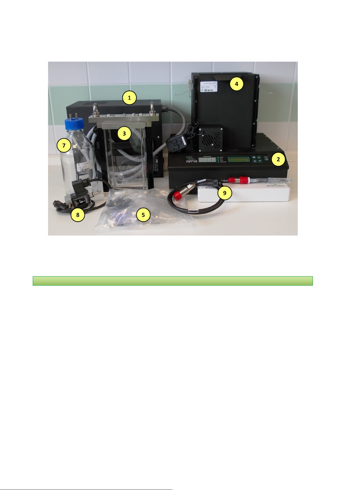
As shown on Fig. 6 on page 14 the FMT150 is shipped with:
1. Power supply wi h he power cord.
. Pho obioreac or wi h in egra ed double-modula ion fluorome er- Ft, Fm, QY and integrated optical density
measurement.
3. Cul iva ion vessel with capacity 400 ml (with holder) for FMT150/400, 1000 ml for FMT150/1000 or 3000 ml for
FMT150/3000.
4. LED panel shield.
5. Spare Par Ki * – for the complete list of Spare Part Kit see Table 3 on page 13 and corresponding Fig. 5
6. User guide ( his documen ) and Sof ware manual.
7. Bubble Humidifier – To maintain stable culture volume.
Components #8 and #9 below are highly recommended for proper functionality of the PBR, but are not included in the
standard configuration and have to be purchased separately.
8. Bubble in errup ion valve wi h air pump (air pump not shown on Fig. 6).
9. pH/ empera ure module.
Page 1
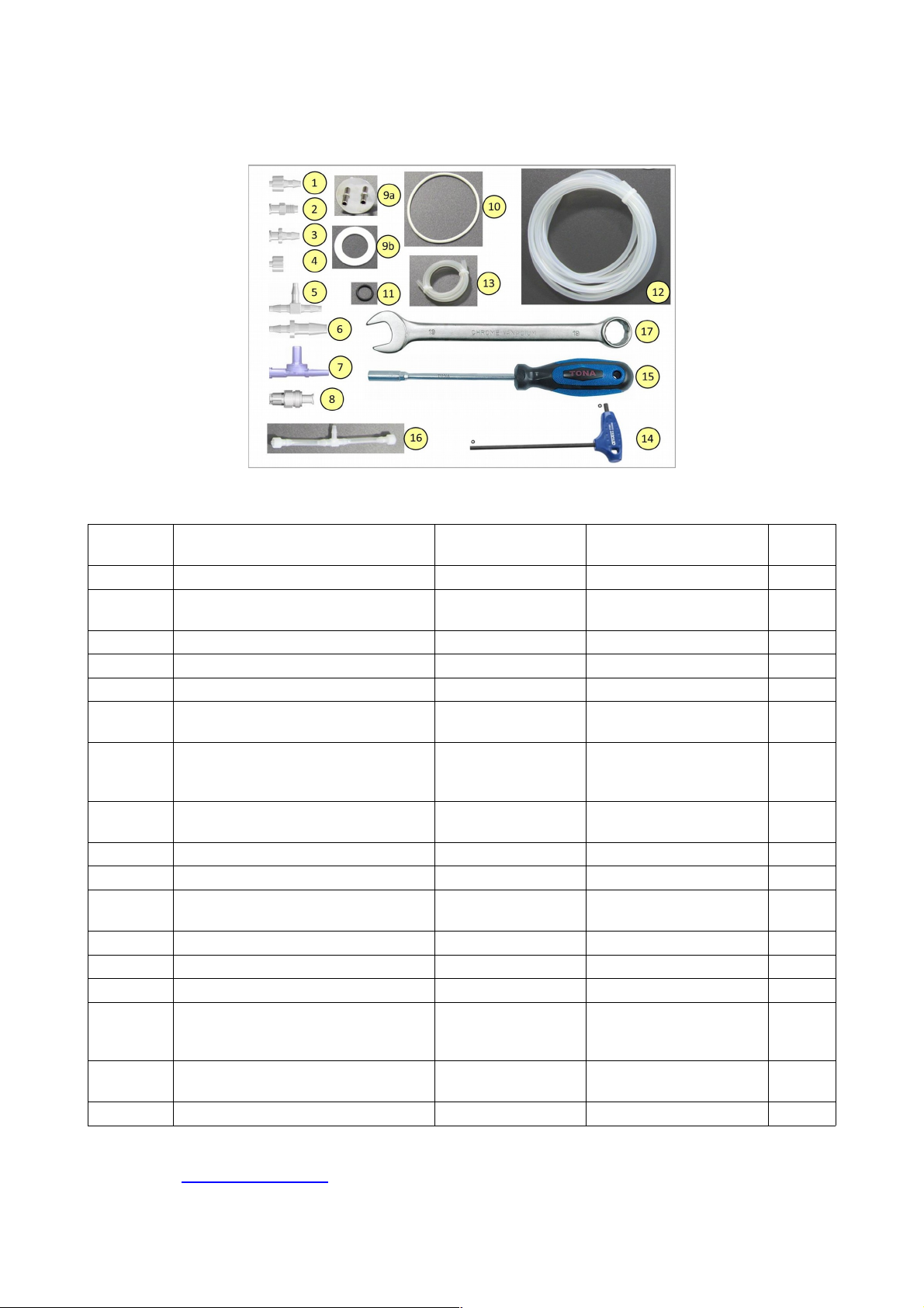
3.Device Description
Componen
Number Componen Descrip ion Specifica ion Explana ion Pcs
1Male Luer Integral Lock MTLL 40-J1A* 5/3 ” (4.0 mm) 10
2Female Luer Thread Style BSFTLL-J1A* 5/16” Hex to 1/4- 8 UNF
Bottom Sealing Thread 10
3Female Luer Thread Style FTLL 40-1* 5/3 ” (4.0 mm) 10
4Male Luer Integral Lock Ring Plug LP4-J1A* 10
5Tee Tube Fitting T40-J1A* 5/3 ” (4.0 mm) 10
6Reduction Tube Fitting 4060-1* 1/4” (6.4 mm) and 5/3 ”
(4.0 mm) 5
7
Double Check Valve DCV118-001* Safety valves that permit gases
and liquids to flow in only one
direction
5
8Check Valve SCV08053* Check valve for with low priming
volume 5
9Metal lid with ports (9a) with silicone ring (9b) Silicon ring 7x4 x mm For humidifier bottle 1+
10 O-ring 75x3 mm Sealing between lid and the vessel 5
11 O-ring 14x mm Sealing to the openings for
optional sensors 10
12 Silicon Tubing Ø 6/3 mm Additional tubing 10 m
13 Silicone tubing Ø 5/ mm Additional tubing 0.5 m
14 Hex Key 5 mm To loosen up the screws of the lid 1
15
Spanner/Screwdriver 8 mm For releasing filler screws in
optional sensor positions and luer
connectors in the vessel lid
1
16 T-tube (silicone tubing with pcs of Male Luer
Lock and 1 pc of Tee Tube Fitting)
Aeration tubing for the vessel 1
17 Wrench 19 mm For releasing sensors 1
Table 3: Lis of spare par ki componen s shown in Fig. 5
* Provided by: www.valueplastics.com
Page 13
Fig. 5: Components of the spare part kit. Numbers correspond to component numbers in Table 3.
3.Device Description
3.3 CONTROL UNIT FRONT PANEL
Photobioreactor Control Unit front panel can be used for simple manual control of the PBR FMT150. By using the keys
on the front panel the operation of cultivation and monitoring units such as pH/temperature sensor, light control, OD
monitoring module, PWM mode or CO and O sensor can be controlled. When FMT150 photobioreactor is purchased
without the Remote Control System for PBR FMT150 then all of the control has to be set up manually using the front
panel of the FMT150 control unit. The user can read out from the display the actual values for the given sensor or
monitoring unit.
Impor an : Please note that no user-defined protocols can be designed and no data recording is possible without the
PC and PBR software.
No e: Please note that neither turbidostat nor chemostat module can be operated if FMT150 is purchased without the
PBR software.
The front panel of the FMT150 control unit has 4 LED lights on the left and 5 control keys on the right (Fig. 7).
Page 14
Fig. 6: Minimal configuration set of the Photobioreactor FMT150. Numbers correspond to component numbers as
described on page 1 .

3.Device Description
3.3.1 LED INDICATORS
Green LED indicator READY is lighting when the current temperature is equal to target temperature.
Orange LED indicator HEAT is lighting when the heater turns on in the cultivation vessel.
Blue LED indicator COOL is lighting when the water in the cultivation vessel is cooled and the Cooling Unit is operating.
The minimal temperature in the standard PBR FMT150 is 10 °C.
Red LED indicator OVERLOAD is lighting when the requested temperature in the cultivation vessel higher than the
current temperature was not reached yet.
3.3. DIGITAL DISPLAY ON THE LEFT
Displays the current temperature in the cultivation vessel and error messages if any problems with the FMT150 occur.
Possible error messages are:
•Er6 – Temperature/pH sensor is not connected.
•Er7 - Temperature sensor is not functional and must be repaired. Please contact support@psi.cz if this error
occurs.
3.3.3 DISPLAY ON THE RIGHT
This display shows various functions of the FMT150 and these are activated and set with the main keys on the right
side of the control unit as described below.
3.3.4 MAIN KEYS
•[M]: Used to move back in the menu tree or to exit the menu.
•[S]: Used to move forward in the menu tree, to save the selection, or to turn ON/OFF.
•[▲]: Used to move up in the menu or to add value.
•[▼]: Used to move down in the menu or to subtract value.
•[Mains]: (On/Off) key doesn't have any function related to the common use of PBR and it is intended only for
service purposes. The Photobioreactor is turned on by switching on the corresponding Power supply.
No e: Please refer to the chapter 8.1 if Photobioreactor FMT150 is purchased without the PBR software and the PBR
FMT150 is to be controlled solely manually via the control unit front panel.
Page 15
Fig. 7: Photobioreactor front panel

3.Device Description
3.4 REAR PANEL FOR VERSION FMT150.1
The rear panel houses connectors for all connecting cables (Fig. 8).
3.4.1 CONNECTOR FOR PH/TEMPERATURE SENSOR
pH/temperature sensor should be plugged to this connector when in use. PBR FMT150 control unit recognizes when
the sensor is connected and will automatically control the operation of the sensor.
3.4. CONNECTOR FOR OPTIONAL SENSOR
O sensor should be plugged to this connector when in use. PBR FMT150 control unit recognizes when the sensor is
connected and will automatically control the operation of the sensor.
No e: Only O sensor can be plugged to this connector.
3.4.3 SERIAL COMMUNICATION CONNECTOR
USB connector with serial communication cable is provided as part of the PBR FMT150 package when purchased with
the PBR software to connect the PBR FMT150 with the computer. This connection has to be made for the
communication of the PBR FMT150 via the PBR software.
3.4.4 AUX1 CONNECTOR
AUX1 connector should be used for the CO sensor, peristaltic pump, additional light or magnetic stirrer (please see
page 0 for detail description of possible connection schemes).
Page 16
Fig. 8: Photobioreactor control unit and its power supply rear panels. A) Back panel of the Photobioreactor
control unit with the serial number (blue arrow). Numbers correspond to the description below. B) Rear
panel of the power supply with the serial number (blue arrow). Note the same serial number. Each
Photobioreactor has its own power supply and it cannot be interchanged with another power supply.

3.Device Description
3.4.5 AUX CONNECTOR
AUX connector is used primarily for the bubble interruption valve, but can be used also for CO sensor, peristaltic
pump, additional light or PWM pump (please see Fig. 10 page 0 for detail description of possible connection
schemes).
3.4.6 POWER SUPPLY CONNECTOR
The power supply unit is plugged into the FMT150 control unit via this connector.
3.4.7 SERVICE COMMUNICATION CONNECTOR
Service communication connector is designed only for servicing the FMT150 by the manufacturer.
Warning: NEVER CONNECT THE SERVICE CABLE TO THIS CONNECTOR (RED ARROW IN Fig. 8A) WITHOUT PRIOR
CONSULTATION WITH THE MANUFACTURER.
3.4.8 IDENTIFICATION LABEL WITH SERIAL NUMBER
Each Photobioreactor FMT150 produced has a serial number that corresponds with the serial number of the power
supply unit. These are always provided together and are not interchangeable. Prior to switching PBR FMT150 device
ON make sure that the serial number on the rear panel of the main body matches the serial number on the power
supply (Fig. 8B).
Warning: Damage can occur when the power supply is incompatible with the PBR FMT150 device.
Page 17

3.Device Description
3.5 REAR PANEL FOR VERSION FMT150.2
The rear panel houses connectors for all connecting cables (Fig. 9). Please note that the numbers in the next section
correspond to the numbers in Fig. 9.
3.5.1 CONNECTOR FOR PH/TEMPERATURE SENSOR
pH/temperature sensor should be plugged to this connector when in use. PBR FMT150 control unit recognizes when
the sensor is connected and will automatically control the operation of the sensor.
3.5. CONNECTOR FOR O SENSOR
O sensor should be plugged to this connector when in use. PBR FMT150 control unit recognizes when the sensor is
connected and will automatically control the operation of the sensor.
3.5.3 USB PBR COMMUNICATION CONNECTOR
USB communication cable is provided as part of the PBR FMT150 package when purchased with the Remote Control
System to connect the PBR FMT150 with the computer. This connection has to be made for the communication of the
PBR FMT150 via the PBR software.
3.5.4 AUX1 CONNECTOR
AUX1 connector should be used for the CO sensor, peristaltic pump, PWM pump, additional light or magnetic stirrer
(please see Fig. 10 on page 0 for detail description of possible connection schemes).
Page 18
Fig. 9: Photobioreactor control unit and its power supply rear panel. A) Back panel of the
Photobioreactor control unit. B) Serial number on the front panel of the of the PBR FMT150 unit. C)
Rear panel of the power supply with the serial number (blue arrow).

3.Device Description
3.5.5 AUX CONNECTOR
AUX connector should be used primarily for the bubble interruption valve but can be also used for CO sensor,
peristaltic pump, additional light (please see see Fig. 10 on page 0 for detail description of possible connection
schemes).
3.5.6 USB TR COMMUNICATION CONNECTOR
USB TR communication connector is designed only for servicing the FMT150 thermoregulator by the manufacturer.
No e: NEVER USE THE USB TR CONNECTOR WITHOUT PRIOR CONSULTATION WITH THE MANUFACTURER.
3.5.7 AUX3 AND AUX4 CONNECTORS
AUX3 and AUX4 connector are additional connectors that can be used for the CO sensor, peristaltic pump, additional
light.
3.5.8 POWER SUPPLY CONNECTOR
The power supply unit is plugged into the FMT150 control unit via this connector.
3.5.9 IDENTIFICATION LABEL WITH SERIAL NUMBER
Each Photobioreactor FMT150 has a serial number that corresponds with the serial number of the power supply unit.
These are always provided together and are not interchangeable. Prior to switching PBR FMT150 device ON make sure
that the serial number on the front panel of the main body matches the serial number on the power supply (Fig. 9C).
Warning: Damage can occur when the power supply is incompatible with the PBR FMT150 device.
3.6 CONNECTION SCHEMA
Depending on the use of optional modules and the set-up of the PBR FMT150, the connection schema for the optional
and standard modules with the PBR FMT150 control unit rear panel may differ. Please refer to Table 4 below to see the
possible order of connecting the different modules to the PBR FMT rear panel.
Devices for which the interconnection is possible can be connected together in a series by AUX IN and AUX OUT
connectors according to the recommended order. Please refer to Fig. 10 for recommended schematic connection setup
for all available modules and accessories.
DEVICE USED PROPER
CONNECTOR
DEVICE
INTERCONNECTION
POSSIBLE
Peristaltic Pump AUX 1/ /3/4 YES
CO module AUX 1/ /3/4 YES
External Light AUX 1/ /3/4 YES
Bubble Interruption Valve AUX NO
Magnetic Stirrer AUX 1 NO
PWM Pump AUX 1 NO
Table 4: Ex ernal connec ors
Impor an : Please note that Bubble Interruption Valve must be always connected to the AUX connector and Magnetic
stirrer and PWM pump always to connector AUX1. In case of magnetic stirrer and PWM Pump, only one of the two
devices can be connected to the PBR FMT150 at one time.
Page 19
3.Device Description
No e: Please note that the AUX3 and AUX4 connectors are available only in the FMT150. .
Page 0
Fig. 10: Schematic of recommended set-up for interconnecting available modules with PBR FMT150 control unit. A)
Scheme valid for FMT150.1 version. B) Scheme valid for FMT150. version.
Table of contents
Other PSI Laboratory Equipment manuals


Popular Laboratory Equipment manuals by other brands


PSC
PSC PowerScan Quick reference guide

AVL DITEST
AVL DITEST IRP 120 user manual

Molecular Devices
Molecular Devices SpectraMax Paradigm user guide

Altronix
Altronix NetWay1DWP installation guide

Syngene
Syngene G:Box Chemi XRQ Installation quick guide

Soilmoisture Equipment
Soilmoisture Equipment 1768B-.15SYS1 quick start guide


