Psiber LANMASTER 30 User manual
PROFESSIONAL NETWORK TESTING & PROTOCOL ANALYSIS
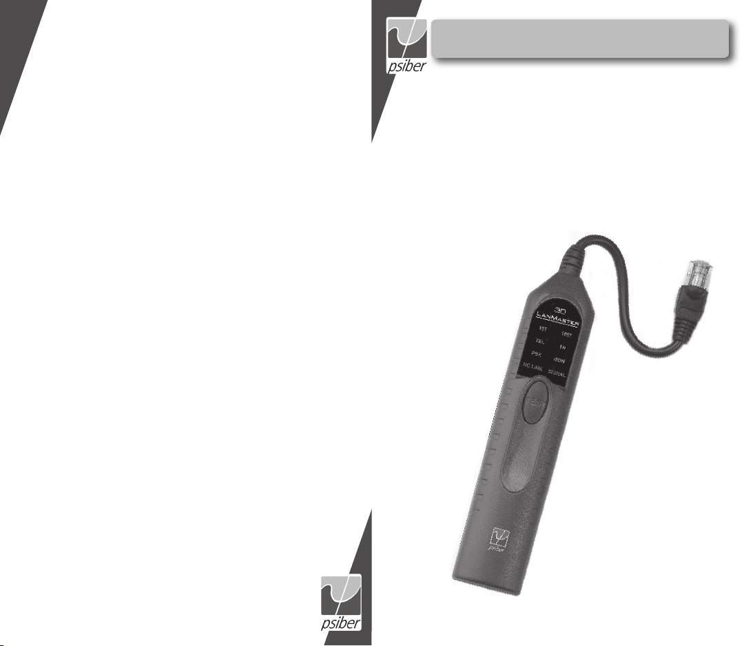
LANMASTER 30
USER’S GUIDE
Psiber US:
Psiber Data Sytems Inc.
7075-K Mission Gorge Road
San Diego, CA 92120
www.psiber.com
Psiber Europe:
Psiber Data GmbH
Felix-Wankel-Str. 4
82152 Krailling
Germany
www.psiber-data.com

3
English
BOX CONTENTS
• LanMaster 30 Outlet Identifier •RJ-45 Coupler
•9 Volt Alkaline Battery •User Guide
BATTERY
The LanMaster 30 operates on one 9 volt alkaline
battery. Remove the battery cover at the bottom
of the unit and insert the battery with the terminal
orientation as shown. Battery polarity is marked on
the back of the battery cover and inside the battery
well for reference.
TECHNICAL OVERVIEW
The LanMaster 30 Outlet Identifier is a comprehensive signal detection,
measurement and identification device. The unit measures signals on every
combination of wire pairs in a four (RJ-11), six (RJ-12) or eight (RJ-45) wire
outlet or plug. The measurements are compared to known signal parameters
for telecommunication and data communication equipment and reported
to the user by illumination of equipment-type LEDs. A “SIGNAL” indicator
is provided to warn when signals are present at the outlet or plug that do
not correspond to known equipment parameters. A “NO LINK” indicator is
illuminated when no signals are detected on any of the wires.
The LanMaster 30 conducts a three step test that is completed in less
than six seconds. The first test measures voltages on all wire pairs and iden-
tifies an Analog, PBX or ISDN telephone circuit. The second test measures
Standard (10baseT) and Fast (100baseTX) Ethernet Link Signals and identi-
fies the operating mode of the far-end equipment. The third test transmits a
Token Ring voltage that causes the unit to be inserted in to a ring and then
measures the current level.
OPERATION
Insert the LanMaster 30 plug end in to the RJ-45 jack of a wall outlet,
or attach to a 4-wire, 6-wire or 8-wire patch cable with the RJ-45 coupler
provided. Press and hold the “TEST” button.

4
English
5
English
Telephone Circuit Identification
While the unit is conducting the telephone
test, the “TEL” indicator will blink on and
off. During the first two seconds of the test,
each combination (64 total) of two wires are
scanned for signals and each voltage meas-
urement is recorded. If telephone line voltage
is detected on wire pair 4,5 and no signals are
present on any other pair, the “TEL” indicator
is illuminated showing that an analog phone
line has been detected. If 24VDC or 48VDC is
detected between wire pairs 3,6 and 4,5 (S/T
interface) or sealing current on pair 4,5 (U interface), the “ISDN” indicator is
illuminated showing that an ISDN circuit has been identified. If appropriate
voltage levels are detected on one or more wire pairs, the “PBX” indicator is
illuminated showing that a PBX type switch or a multiple line phone circuit
has been detected.
NOTE: If voltages above expected levels are measured, the “SIGNAL”
indicator is lit showing that an unknown and potentially damaging voltage is
present. The user should identify the equipment installed at the far-end prior
to connecting any devices to the outlet under test.
10baseT/100baseTX Link Identification
While the unit is conducting the 10baseT/100baseTX Link test, the
“10T” and “100T” indicators will blink on and off. If an MLT-3 waveform is
detected or a Link Code Word is decoded for
100baseTX operation, the “100T” indicator is
illuminated showing a 100baseTX connection.
If a Normal Link Pulse (NLP) is detected or
a Link Code Word is decoded for 10baseT
operation, the “10T” indicator is illuminated.
If a Link Code Word is decoded for 10/100
auto-negotiation, both the “10T” and “100T”
indicators are illuminated showing that the far
end equipment is capable of auto-negotiating
to either the 10baseT or 100baseTX mode of operation. The LanMaster 30
does not test 100baseT4. The “SIGNAL” indicator will be illuminated if a Link
Code Word is detected that is invalid or contains a reported Fault or the MLT-
3 waveform frequency is incorrect.
Token Ring Link Identification
While the unit is conducting the Token Ring Link test the “TR” indicator will
blink on and off. The Model 30 transmits the
standard Token Ring phantom voltage between
wire pairs 3,6 and 4,5. If the measured current
is within the correct range, the voltage is main-
tained to allow the unit to be inserted into the
ring. Once inserted in the ring, the “TR” indica-
tor is illuminated . The “SIGNAL” indicator is lit
if the current is below the specified operating
range, indicating a possible open wire.
No Link – Blinking/Continuous
When no signals are detected during any of the three previous tests, wire
pairs 3,6 and 4,5 are checked for continuity. The “NO LINK” indicator will
blink on and off when continuity is detected. Continuity typically shows that
the outlet is connected to an unpowered 10/100 Ethernet port or a discon-
nected Type 1 Token Ring connector is at the far end. When no signals or
continuity are measured, the “NO LINK” indicator is illuminated continuously.
Total time to complete all tests is less than eight seconds.
BATTERY LIFE
Low Battery - When the battery is below the level required for the LanMaster
30 to operate properly, the “SIGNAL” indicator blinks on and off while a test is
being conducted.
COMPUTER NIC TESTING
The LanMaster 30 is designed to test a wall outlet which provides the
Ethernet signals on pins 3,6 of the RJ-45 jack. To test a computer Network
Interface Card (NIC), a crossover cable or a crossover coupler which swaps
wire pairs/pins1,2 with 3,6 must be used. A crossover coupler is provided as
part of the optional Model AP-2 Accessory Pack.
ACCESSORY PACK
An optional Accessory Pack is availble for the LanMaster 30. The Model
AP-2 Accessory Pack includes a soft-sided nylon carrying case, a 12” RJ-11
patch cable for testing RJ-11 style outlets and an RJ-45 crossover coupler
required to test a computer NIC.

6
English
7
APPLICATIONS
Moves, Adds and Changes - Reduce risk of equipment damage by identify-
ing the correct outlets for connecting telephone and network devices.
Installation - Verify physical layer connectivity to the far- end equipment.
Trouble Calls - Reduce troubleshooting time by ensuring the connection is
correct and outlet is functional. Prevent damage to sensitive test equipment
by identifying outlet type before running tests.
Telecom System Management - Locate expensive unused analog phone
circuits for reassignment or termination.
Network Management - Identify Ethernet Link data rate (10Mbps or
100Mbps) and support for auto-negotiation.
ETHERNET LINK SIGNAL OVERVIEW
Three different signals can be used to establish an Ethernet Link: a Link
Code Word, an NLP or an MLT-3 waveform. The Link Code Word is specific
in both Link speed and duplex mode. The NLP is specific in speed (10Mbps)
but ambiguous in duplex mode (half or full). The MLT-3 waveform is also
specific in speed (100Mbps) but ambiguous in duplex mode. Duplex modes
for equipment that use NLP or MLT-3 signaling must be carefully managed to
ensure proper Link operation.
WARRANTY
Psiber Data warrants that the product shall be free from defects in parts or workmanship for a period of 12 months from the
date of purchase if used in accordance with Psiber Data operating specifications.
THIS IS THE ONLY WARRANTY MADE BY Psiber Data AND IS EXPRESSLY MADE IN LIEU OF ALL OTHER WARRAN-
TIES EXPRESSED OR IMPLIED, INCLUDING BUT NOT LIMITED TO ANY IMPLIED WARRANTIES OF MERCHANTABI-
LITY OR FITNESS FOR ANY PARTICULAR PURPOSE.
Should any parts or workmanship prove defective, Psiber Data will repair or replace at Psiber Data’ option, at no cost to the
Buyer except for shipping costs from the Buyer’s location to Psiber Data. This is Buyer’s SOLE AND EXCLUSIVE REMEDY
under this Agreement. This warranty does not apply to products which have been subject to neglect, accident or
improper use, or to units which have been altered or repaired by other than an authorized repair facility.
For US-Customers:
Return of Equipment – To return a product to Psiber Data Systems Inc., first obtain a Return Authorization number from our
Customer Service by calling +1 619-287-9970. The RA# must be clearly marked on the shipping label, or the package will
not be accepted by Psiber Data Systems Inc. See sample label below.
To: Psiber Data Sytems Inc.
7075-K Mission Gorge Road
San Diego, CA 92120
RA# XXXXXXXX
For European-Customers:
Return of Equipment – To return a product to Psiber Data GmbH, first obtain a Return Authorization number from our
Customer Service by calling +49-89-89136060. The RA# must be clearly marked on the shipping label.
To: Psiber Data GmbH
Felix-Wankel-Str. 4
82152 Krailling
Germany
RA# XXXXXXXX
Copyright 2009 Psiber Data. All rights reserved. LanMaster, psiber and the Psiber logo are trademarks of Psiber Data.
Deutsch
LIEFERUMFANG
• LanMaster 30 Anschlusserkennung •9 Volt Alkali-Batterie
• RJ-45 Durchführungskupplung •Benutzerhandbuch
BATTERIE
Der LanMaster 30 arbeitet mit einer 9 Volt Alkali-
Batterie. Entfernen Sie die Batterieabdeckung am
unteren Teil des Gerätes und setzen Sie die Batterie
gemäß Zeichnung ein. Die korrekte Polarität der Batterie
finden Sie sowohl auf der Batterieabdeckung als auch
auf der Innenseite des Batteriefachs eingedruckt.
TECHNISCHE ÜBERSICHT
Der LanMaster 30 ist vielseitig einsetzbar für: Signalerfassung, Messung und
Identifizierung. Das Gerät misst Signale in jeglicher Adernpaarkombination an ei-
ner Anschlussbuchse oder einem Stecker mit 4 (RJ-11), 6 (RJ-12) bzw. 8 (RJ-45)
Adern. Die Messungen werden mit bekannten Signalparametern für Telekommu-
nikations- und Datenkommunikationsgeräte verglichen und dem Benutzer durch
unterschiedliche LEDs angezeigt. Die Anzeige „SIGNAL“ warnt den Benutzer,
wenn Signale am Stecker oder an der Buchse vorhanden sind, die nicht mit den
bekannten Geräteparametern übereinstimmen. Die „NO LINK“ Anzeige leuchtet
auf, wenn überhaupt kein Signal auf den Adernpaaren detektiert werden kann.
Der LanMaster 30 führt einen aus 3 Einzeltests bestehenden Test innerhalb
von weniger als 6 Sekunden durch. Im ersten Test wird die Spannung an allen
Adernpaaren gemessen und erfasst, ob es sich um ein analoges Telefon, eine
analoge Telefonanlage (PBX) oder um ISDN Telefonleitungen handelt. Der zweite
Test prüft auf Standard (10BaseT) und Fast (100BaseTX) Ethernet Link-Signale
und ermittelt den Betriebsmodus des Endgerätes. Im dritten Test wird Token Ring
Spannung übertragen, so dass das Gerät in einen Ring eingeschleift wird und
dann die Ringgeschwindigkeit misst (4 Mbit/s oder 16 Mbit/s).
BEDIENUNG
Stecken Sie das LanMaster 30 Kabel in die RJ-45 Buchse einer Wanddose
oder verbinden Sie es über die mitgelieferte RJ-45 Durchführungskupplung mit
einem 4-, 6- oder 8-adrigen Patchkabel. Drücken Sie die Taste „TEST“ und halten
Sie diese gedrückt.
Identifikation von Telefonleitungen
Während das Gerät den Telefontest durchführt, blinkt die „TEL“ Anzeige.
Während der ersten zwei Sekunden des Tests wird jede mögliche 2-paarige
This manual suits for next models
1
Other Psiber Test Equipment manuals


Popular Test Equipment manuals by other brands


Redtech
Redtech TRAILERteck T05 user manual

Venmar
Venmar AVS Constructo 1.0 HRV user guide

Test Instrument Solutions
Test Instrument Solutions SafetyPAT operating manual

Hanna Instruments
Hanna Instruments HI 38078 instruction manual

Kistler
Kistler 5495C Series instruction manual

Waygate Technologies
Waygate Technologies DM5E Basic quick start guide

StoneL
StoneL DeviceNet CK464002A manual

Seica
Seica RAPID 220 Site preparation guide

Kingfisher
Kingfisher KI7400 Series Training manual

Kurth Electronic
Kurth Electronic CCTS-03 operating manual

SMART
SMART KANAAD SBT XTREME 3G Series user manual

Agilent Technologies
Agilent Technologies BERT Serial Getting started