PTZOptics PT-JOY-G2 User manual

®
Ver. 1.0 –8.29.2017
Page1
PTZOptics
IP Joystick Controller
Second Generation IP Joystick Controller
Installation & Operation Manual
Please visit www.ptzoptics.com for the most up to date version of this manual

®
Ver. 1.0 –8.29.2017
Page2
Table of Contents .
Precautions
Safety Tips…………………..……………..……………..……………..……………..……………..……………...........
Page 3
Requirements……………..……………..……………..……………..……………..……………..……………...........
Page 3
What’s in the Box……………..……………..………..…..……………..……………..……………..………………………
Page 3
Physical Descriptions
Top View of Joystick………………..……………..……………..……………..……………..………………………….
Page 4
Back View of Joystick…..……………..……………..……………..……………..……………..………………………
Page 5
Hardware Setup
Power……………..……………..…………………..……..……………..……………..……………..……………..….…..
Page 6
Network……………..……………..……………..………………….……..……………..……………..………………..…
Page 6
“Quick Start” – Basic Operation
Initial setup for joystick controller on a LAN……………..……………..……………..……………………...
Page 7
Adjusting the default language………………….……………..……………..……………..……………………...
Page 7
Assigning a static IP to the joystick controller.…………..……………..……………..……………………...
Page 8
Search, Add and Inquire………………..……………..……………..……………..……………………………..……
Page 11
Switching between cameras..………..……………..……………..……………..……………………………..……
Page 14
Controlling cameras…….………………..……………..……………..……………..……………………………..……
Page 15
Setting and Calling Presets…………..……………..……………..……………..……………………………….……
Page 16
IP Interface walkthrough
Logging in…………………………..……………..……………..…………………..………………..……………………...
Page 17
LAN………..…………………………..……………..……………..…………………..………………..……………………...
Page 19
Users……..…………………………..……………..……………..…………………..………………..……………………...
Page 20
Upgrade……………………………..……………..……………..…………………..………………..……………………...
Page 21
Factory restore…………………..……………..……………..…………………..………………..……………………...
Page 21
Reboot……………………………..……………..……………..…………………..………………..…………………….....
Page 22
Troubleshooting……………..……………..………………..……………..…………………….……..………………………
Page 23
Notes……………………………..……………..………………..……………..………………….….……..………………………
Page 24

®
Ver. 1.0 –8.29.2017
Page3
Precautions .
Safety Tips .
•Please read this manual carefully before using the joystick controller.
•Avoid damage from stress, violent vibration or liquid intrusion during
transportation, storage, or installation.
•Do not apply excessive voltage, use only the specified voltage. Otherwise, you
may experience an electrical shock.
•Keep the joystick controller away from strong electromagnetic sources.
•Do not clean the joystick controller with any active chemicals or corrosive detergents.
•Do not disassemble joystick controller or any of the joysticks's components. If problems
arise, please contact your authorized dealer.
•After long term operation, moving components can wear down. Contact your
authorized dealer for repair.
Requirements .
•The joystick controller will require the presence of a DHCP server on your network for initial
configuration (IP address is set to DHCP by default)
•The joystick controller is unable to span subnets; the IP camera and joystick controller must be
in the same subnet of the LAN (example –192.168.1.123 & 192.168.1.111 belong to the same
subnet; 192.168.1.123 & 192.168.0.125 do not)
•The joystick controller requires that the IP camera being controlled is fully ONVIF-S compliant,
with ONVIF capabilities enabled, or the joystick will not properly control the camera.
oWhen being used with a PTZOptics camera please make sure that in the web interface of
the camera you have enabled “ONVIF:” to “On” under the “Network” section.
oWhen being used with a PTZOptics camera please make sure that in the web interface of
the camera you have enabled “ONVIF AUTH:” to “Off” under the “Network” section.
oPlease reboot the camera if these settings were originally in the incorrect state.
What’s in the Box .
Supplied Hardware .
•PT-JOY-G2
oPT-JOY-G2 Joystick Controller
oPower Supply
oUser Manual (This Document)

®
Ver. 1.0 –8.29.2017
Page4
Physical Descriptions .
Top View of Joystick Controller .
1. Status / Menu LCD
2. Command Keypad
3. Alpha-numeric Keypad
4. Tuning Keypad
5. 4D Joystick
1
2
3
5
4

®
Ver. 1.0 –8.29.2017
Page5
Back View of Joystick Controller .
1. Power LED Light (red) and Connection LED Light (green)
2. RS-232 Port (Not active on this model)
3. LAN Port (PoE enabled to power joystick controller from an 802.3af switch)
4. RS-485 Port (Not active on this model)
5. 12 VDC Power Input
1
2
3
4
5

®
Ver. 1.0 –8.29.2017
Page6
Hardware Setup .
Power .
Note: the joystick controller has a long boot-up procedure that can sometimes take up to 60
seconds to complete
•Standard Outlet
oUsing the supplied power adaptor connected the 12 VDC Power Input port
•Power over Ethernet (PoE) complying with the 802.3af standard via the RJ45 port on the
joystick controller
Network .
Note: The joystick controller will require the presence of a DHCP server on your network for
initial configuration (IP address is set to DHCP by default)
•Connect a network cable from the RJ45 port on the joystick controller to your LAN
NOTE: Failure to follow these sequences may result in no connection.

®
Ver. 1.0 –8.29.2017
Page7
“Quick Start” Basic Operation .
Initial setup for joystick controller on a LAN .
Please ensure you have followed the steps on the previous pages for properly
connecting your joystick controller to a proper power source (outlet or PoE)
Please ensure you have followed the steps on the previous pages for properly
connecting your joystick controller to a LAN that has a DHCP server present
•After everything is connected please wait for the joystick controller to complete its
bootup cycle (up to 60 seconds)
oOnce the bootup cycle has completed the LCD panel will display the joystick
controllers current IP address as assigned by the local DHCP server on the LAN
•The joystick controller is now ready to have cameras added
Adjusting the default language .
•If the joystick controller displays the incorrect language please follow the steps below
to adjust to the desired language
oPress the “SETUP” button to enter configuration mode
oThe first MENU displayed on the LCD is the language setting
oUsing the joysticks “Pan,” left / right, capability adjust the current setting to
your desired language
Example: English is displayed as EN
oPress the “ENTER” button
oPress the “ESC” button

®
Ver. 1.0 –8.29.2017
Page8
Assigning a static IP to the joystick controller .
Using the joystick controller .
Note: When using the joystick controller with a static IP address you must ensure that
the joystick controller is assigned to the same subnet as the IP cameras to be controlled
•Once you have completed the steps above to add your joystick controller to a LAN
with a DHCP server you can assign a static IP for the joystick controller
•Press the “SETUP” button to enter configuration mode
•Use the joystick (up / down) to navigate the menu on the LCD screen to menu item
“02/04” or “IP”
oUse the joystick (right / left) to navigate the menu on the LCD screen to change
the current setting of “DHCP” to “STATIC”
oPress the “Enter” button
oYou will now be prompted to enter your static “IP ADDRESS:” using the alpha-
numeric keypad
▪Enter the static IP address using the “.” between octets as appropriate
Example: “192.168.100.88”
•Note: the joystick controller MUST be on the same subnet as the
IP cameras to be controlled
▪Press the “Enter” button
oYou will now be prompted to enter your static “SUBNET MASK:” using the
alpha-numeric keypad
▪Enter the subnet mask using the “.” between octets as appropriate
Example: “255.255.255.0”
▪Press the “Enter” button
oYou will now be prompted to enter your static “GATEWAY:”, or Default
Gateway, using the alpha-numeric keypad
▪Enter the gateway using the “.” between octets as appropriate
Example: “192.168.100.1”
▪Press the “Enter” button
•The joystick controller will now ask you to confirm that you want to apply these
settings
oPress the “ENTER” button to confirm and allow the device to reboot
oPress the “ESC” button to cancel the entry of the static IP
•You will now see the static IP address displayed on the LCD once the joystick controller
has completed its bootup cycle

®
Ver. 1.0 –8.29.2017
Page9
Using the web interface .
Please ensure you have followed the steps on the previous pages for properly
connecting your joystick controller to a LAN; in this instance, your PC must also be in
the same subnet as your joystick controller on the LAN.
•Using the IP address displayed on the LCD screen of the joystick controller, after
bootup, you can access the IP interface of the joystick controller
•Please enter the IP into a standard web browser (Chrome, IE, Firefox, Safari, etc…)
Example: joystick controller IP = 192.168.100.88
http://192.168.100.88
Note: If the language is not displayed properly please use the third (3rd) drop down
menu to select the appropriate language
•Please enter the default login credentials into the available fields
oDefault user name is “admin”
oDefault password is empty / nothing “”
•You can now click the “Login” button on the web interface
•You will be greeted with the “main page” as displayed below
•The “main page” has a button with a gear for a logo in the top right corner
•Click the gear button to be taken to the “Setup” page

®
Ver. 1.0 –8.29.2017
Page10
•Using the drop down menu labled “Network Type” set that option to “Static Address”
to enable the static IP capabilities of the joystick controller
•Once you have entered all the necessary network credentials please click the “Save”
button
•Reboot the joystick controller, using the “Reboot” option from the Setup page for the
new IP address to fully commit

®
Ver. 1.0 –8.29.2017
Page11
Adding cameras .
Using the joystick controller .
Please ensure you have followed the steps on the previous pages for properly
connecting your joystick controller to a LAN
•Once the joystick controller has completed its bootup cycle press the “SEARCH”
button
•Once the search has completed the LCD will display a list of all ONVIF-S compatible
devices, such as PTZOptics cameras, on your LAN
oUse the joysticks tilt capability to scroll, up / down, through the list of devices
oPress the “ADD” button when you have found the device you wish to use
Note: The device username and password may be required
Example: For a PTZOptics camera with default credentials you would use a
username of “admin” and a password of “admin”
oPlease enter the login credentials when prompted using the alpha-numeric
keypad
Example: to enter the letter “c” you would press the “2” button three (3) times
Note: The username & password is typically set on the IP camera
oPress the “ENTER” button to finish
•Use the joysticks tilt capability to scroll, up / down, through the list of devices
discovered on your network and continue adding, per the steps above, any additional
cameras for IP control
•When all desired cameras have been added press the “ESC” button to return to the
main menu
•You have now successfully added the cameras for IP control

®
Ver. 1.0 –8.29.2017
Page12
Using the web interface .
Please ensure you have followed the steps on the previous pages for properly
connecting your joystick controller to a LAN; in this instance you PC must also be in the
same subnet as your joystick controller on the LAN.
•Using the IP address displayed, after boot up, on the LCD screen of the joystick
controller you can access the IP interface of the joystick controller
•Please enter the IP into a standard web browser (Chrome, IE, Firefox, Safari, etc…)
Example: joystick controller IP = 192.168.100.88
http://192.168.100.88
Note: If the language is not displayed properly please use the third (3rd) drop down
menu to select the appropriate language
•Please enter the default login credentials into the available fields
oDefault user name is “admin”
oDefault password is empty / nothing “”
•You can now click the “Login” button on the web interface
•You will be greeted with the “main page” as displayed below
•The “main page” contains three (3) sections
oA “search results list” (green pane)
oAn “added devices list” (blue pane)
oAn “equipment details” section (orange pane)
oThere is a fourth section for manually adding cameras, without a search, that
can be accessed by clicking the “Handle” button

®
Ver. 1.0 –8.29.2017
Page13
•Click the “Search” button under the “Search Results List”
oYou should now see the status of “Scanning” under the “Search Results List”
oOnce completed you should see any available ONVIF devices on the same
network displayed in the green pane
oNote: if you do not see any devices in the search list please make sure that
ONVIF is enabled on the desired device(s) and that you are on the same subnet
as those devices
oHighlight the camera you wish to add and click the “Add” button
▪If you want to add more than one (1) camera at a time please highlight
your first device in the “Search Results List,” hold the “Ctrl” key and use
the mouse to select any additional devices. Click the “Add” button
when you are done making your selection
▪If you wish to add all discovered devices to the “Added Devices List”
please click the “Add All” button
oWhen the camera(s) you wish to add are all in the “Added Devices List” click
the “Save” button under the “Equipment Details” section
▪You may have noticed that each device is assigned a [0] in front by
default; this is your camera ID for quick switching. If you wish to use
this feature you must simply highlight the device in the “Added Devices
List” and change the “Address” field to a unique ID between 0 and 253.
Don’t forget to click “Save” when you’re finished.
Note: this will be helpful when trying to switch between cameras from
the joystick controller interface
•To manually add a device on the same subnet as yourself please click the “Handle”
button at the bottom of the “Added Devices List”
oEnter the IP address of the device
oEnter the ONVIF port that the device uses
Note: each device may use a unique ONVIF port
a PTZOptics camera will use port 81 by default
oEnter any login credentials required for an
ONVIF connection
Note: PTZOptics camera will use a login of
admin and a password of admin in a defaulted
state
oOnce all information has been properly
added click the “Save” button

®
Ver. 1.0 –8.29.2017
Page14
Switching between cameras .
Please ensure you have followed the steps on the previous pages for properly
connecting your joystick controller to a LAN and then for properly adding cameras to
the joystick controller with unique addresses / IDs provided for each device
•Once multiple devices have successfully been added to the joystick controller you
have two (2) options for switching between these devices
oThe "CAM 1” through “CAM 4" keys will allow for quick switching between the
cameras you currently have provided an “Address” or ID for in the “Equipment
Details Section”
Example an assigned Address / ID of 1 would be “CAM 1”
▪Once selected, you can control pan, tilt, zoom and more for the
selected camera using the joystick controller
oThe “IP” key will allow discrete camera selection based on the assigned
Address / ID
▪Press the “IP” key and enter the address / ID you have assigned to the
camera you wish to control
▪Click the “Enter” button
•Once selected, you can control pan, tilt, zoom and more for the
selected camera using the joystick controller
Note: If the LCD displays “Equipment offline” for a particular camera, please check if
the LAN connection to the camera is live and that the camera is powered on
Note: If the LCD displays “Username or Password Error”, please check that the added
device’s user name and password have been added in that device’s configuration. For
PTZOptics cameras please ensure that the “ONVIF AUTH:” is set to “Off” in the
“Network” settings found on thwe web interface.
Note: Press the “ESC” key to return to the top LCD menu at any time.
Note: Press the “INQUIRE” key, while in the top LCD menu, to see the saved cameras
at any time. Use the joystick Tilt controls to scroll through the cameras.
Note: The “LINK” LED on rear of keyboard will illuminate green any time a camera is
successfully connected to.

®
Ver. 1.0 –8.29.2017
Page15
Controlling cameras .
Please ensure you have followed the steps on the previous pages for properly
connecting your joystick controller to a LAN and then for properly adding cameras to
the joystick controller with unique addresses / IDs provided for each device
•Connect to one (1) of your added cameras using the steps provided above
oUse the joystick on the joystick controller in the up and down directions to TILT
oUse the joystick on the joystick controller in the left and right directions to PAN
oUse the joystick on the joystick controller to move in diagonal directions
allowing for PAN and TILT simultaneously
▪The “SPEED” button will cycle through 3 variations of PAN and TILT
maximum speeds.
▪The LCD will display which speed you have selected as a quantity of
arrows (1-3).
Note: The joystick is progressive, i.e. you can also pan and tilt at
varied rates without changing max speed by moving joystick nearer or
further from its center position.
oUse the joystick on the joystick controller and twist it clockwise to ZOOM IN
▪You can also use the “ZOOM+” button on the joystick controller
oUse the joystick on the joystick controller and twist it counter-clockwise to
ZOOM OUT
▪You can also use the “ZOOM-” button on the joystick controller
Note: You can begin panning or tilting with the joystick and then begin zooming
in or out on an object but you cannot start zooming and then try to pan or tilt.
oYou can manually adjust the focus using the “Focus+” or “Focus-“ buttons
▪When pressed these buttons will automatically put the camera into a
“Manual Focus” mode
▪To return to an auto-focus mode simply press the “AUTO FOCUS”
button, or use the Zoom in or Zoom out button or from the joystick
oYou can manually adjust the exposure settings using the “IRIS+” or “IRIS-“
buttons
▪When pressed these buttons will automatically put the camera into a
“Manual Exposure” mode
▪To return to an auto-exposure mode simply press the “AUTO EXP”
button

®
Ver. 1.0 –8.29.2017
Page16
Setting and Calling Presets .
Please ensure you have followed the steps on the previous pages for properly
connecting your joystick controller to a LAN and then for properly adding cameras to
the joystick controller with unique addresses / IDs provided for each device
•Connect to one (1) of your added cameras using the steps provided above
oTo set a preset move you camera to the desired location for your preset
oPress the “SET” button
▪Enter an ONVIF Preset Number for that camera [1..255] using the
alpha-numeric keypad
▪Press “ENTER” to commit the preset to the camera
oTo recall a preset press the “CALL” button
▪Using the alpha-numeric keypad enter the preset number associated
with the preset you want to use
▪Press the “ENTER” button to call the preset and have the camera move
to that preset location

®
Ver. 1.0 –8.29.2017
Page17
Web interface .
Logging in .
Please ensure you have followed the steps on the previous pages for properly
connecting your joystick controller to a LAN; in this instance, your PC must also be in
the same subnet as your joystick controller on the LAN.
•Using the IP address displayed on the LCD screen of the joystick controller, after
bootup, you can access the IP interface of the joystick controller
•Please enter the IP into a standard web browser (Chrome, IE, Firefox, Safari, etc…)
Example: joystick controller IP = 192.168.100.88
http://192.168.100.88
Note: If the language is not displayed properly please use the third (3rd) drop down
menu to select the appropriate language
•Please enter the default login credentials into the available fields
oDefault user name is “admin”
oDefault password is empty / nothing “”
•You can now click the “Login” button on the web interface

®
Ver. 1.0 –8.29.2017
Page18
•You will be greeted with the “main page” as displayed below
•We have covered the operation of the “main page” in the earlier section for “Adding
Cameras” and will now look into the “Setup” page in more detail
•The “main page” has a button with a gear for a logo in the top right corner
•Click the gear button
Note: The “main page” can always be reached by clicking the viewing button that looks
like an eye in the upper right of the screen next to the gear button.

®
Ver. 1.0 –8.29.2017
Page19
LAN .
•Click on “LAN” on the left side of the page
•You can modify the IP address type and parameters in LAN settings, as follows:
•Select the network type (Static IP or Dynamic Addressing / DHCP) from the drop down
menu
oDynamic addressing (or DHCP, is the default): The keyboard will automatically
request an IP address from a DHCP server on the connected LAN.
▪The auto-assigned address will be displayed on the LCD after the
request to the DHCP server is successful
▪You can always check the assigned IP address by viewing screen 03/04
of the keyboard’s SETUP menu as described previously
Note: Changing IP settings will require a reboot of the keyboard
oStatic Address: When the user needs to set up a network without a DHCP
server or wants to manually assign an IP address, even if there is a DHCP
server, the network type should be set to “Static Address”.
▪A new field containing 4 boxes for the 4 octets of an IP address will
become available for entering this info.
▪Similarly, you will be required to manually enter the Subnet Mask and
Default Gateway for the network.
Note: If you are unsure of what to enter, please see your IT staff for this
information.
Note: Changing IP settings will require a reboot of the keyboard.
oPorts: You may assign default network ports to handle various features of the
connection. The allowable port ranges are shown to the right of the field. It
is recommended to use the default port values (8009, 80, 8010, 554).
Note: Changing Port settings will require a reboot of the keyboard.

®
Ver. 1.0 –8.29.2017
Page20
User management .
•Click on “Users”on the left side of the page
•You can store up to ten (10) unique accounts on the joystick controller; below we will
discuss the attributes of each set of access rights. The default user is “Admin” with
“Super Admin” rights.
oSuper Admins
▪May add a new “Admin” account.
▪Full permission to add, revise or delete any type of account.
▪Configure and revise the keyboard, including all camera parameters.
oAdministrator
▪Full permission to add, revise or delete any type of account, except
Super Admin.
▪Configure and revise the keyboard, including all camera parameters.
oOperator
▪No permissions to manage accounts or configuration.
▪Add, delete and set camera parameters.
oVisitor
▪No permissions to manage accounts, configuration or camera
parameters.
▪May only browse pages and parameters.
This manual suits for next models
1
Table of contents
Other PTZOptics Controllers manuals

PTZOptics
PTZOptics PT-BRDCSTR User manual
PTZOptics
PTZOptics PT-JOY-G4 User manual

PTZOptics
PTZOptics PT-SUPERJOY-G1 User manual
PTZOptics
PTZOptics PT-SUPERJOY-G1 User manual
PTZOptics
PTZOptics PT-JOY-G4 User manual

PTZOptics
PTZOptics PT-JOY-G4 User manual

PTZOptics
PTZOptics PT20XSE-PRODUCER-JOY4 User manual
Popular Controllers manuals by other brands

GM-Racing
GM-Racing 7156 Genius Race II 80R manual
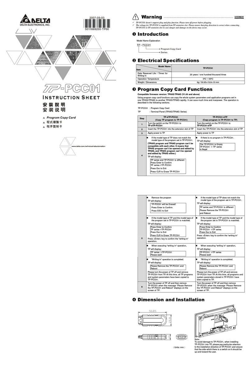
Delta Electronics
Delta Electronics Program Copy Card TP-PCC instruction sheet

JS Led Power
JS Led Power HM-12RGB8A3-DMX512 manual
Eaton
Eaton SCD24 installation guide
Siemens
Siemens SIKOSTART 3RW34 instructions
Taylor Products
Taylor Products T4000 Quick reference guide

