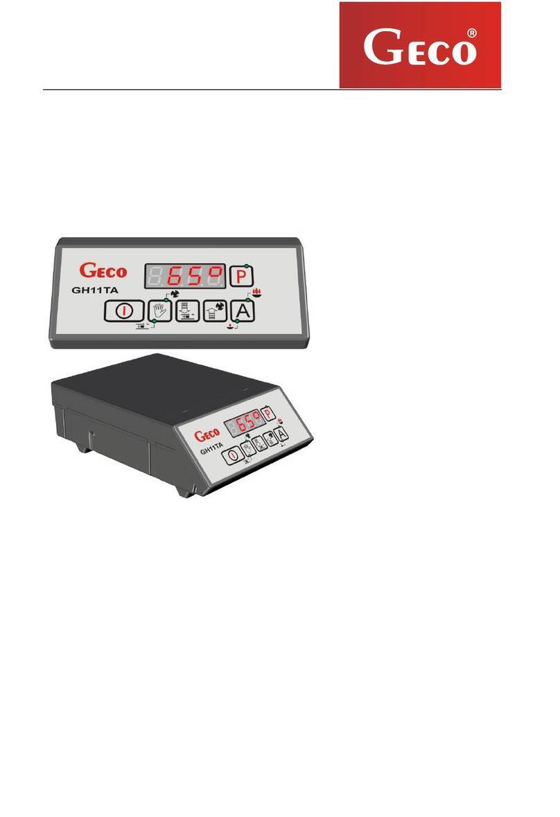
Geco GH07EB User manual

Heating controller GH07EB
For electrode (ion) boilers
User manual
Attention
We strongly recommend that you familiarise yourself fully with the contents of this
manual before installing and using any of our devices. If you have any questions, please
contact us between 08:00 and 16:00. At the bottom of every page is the date of latest
publication. Please always use the latest version of the instructions, which you can obtain, post
free, upon request.

Page 2 Edition I 03.12.2012
Table of contents
1.
DE CRIPTION OF CONTROLLER.......................................................................................................................3
2.
TECHNICAL DETAIL . .........................................................................................................................................4
3.
REQUIREMENT FOR ELECTRICAL IN TALLATION......................................................................................4
4.
GRAPHIC AND TEXT DE CRIPTION OF CONTROLLER IN TALLATION .....................................................5
5.
CONTROLLER MODE .........................................................................................................................................6
5.1.
TANDBY MODE
..............................................................................................................................................7
5.2.
A
UTOMATIC MODE
..........................................................................................................................................7
5.3.
M
ANUAL MODE
...............................................................................................................................................8
5.4.
A
LARM MODE
.................................................................................................................................................8
6.
OPERATING THE CONTROLLER .......................................................................................................................8
6.1.
C
ONTROLLER FA CIA PANEL
............................................................................................................................9
6.2.
O
VERVIEW OF TEMPERATURE ETTING
........................................................................................................10
6.3.
M
ANUAL MODE
–
CONNECTED DEVICE
..........................................................................................................10
6.4.
E
DIT U ER PARAMETER
...............................................................................................................................11
7.
DE CRIPTION OF ADDITIONAL FUNCTION ................................................................................................12
7.1.
DHW
PRIORITY
...........................................................................................................................................12
7.2.
UMMER MODE
.............................................................................................................................................12
7.3.
A
NTI
-
LEGIONELLA FUNCTION
........................................................................................................................12
8.
OPERATING Y TEM IN TALLATION ..........................................................................................................14
8.1
H
EATING IN TALLATION NR
1.......................................................................................................................14
8.2
H
EATING IN TALLATION NR
2.......................................................................................................................15
8.3
H
EATING IN TALLATION NR
3.......................................................................................................................16
9.
ALARM . .............................................................................................................................................................17
10.
TEMPERATURE LIMITER ( TB).................................................................................................................17
11.
POWER FAILURE. .........................................................................................................................................18
12.
ROOM THERMO TAT. .................................................................................................................................18
12.1
GA01HD
ROOM PANEL
................................................................................................................................18
12.2
R
OOM THERMO TAT
.....................................................................................................................................19
13.
INFORMATION REGARDING THE LABELING AND DI PO AL OF WA TE ELECTRICAL AND
ELECTRONIC EQUIPMENT.........................................................................................................................................19

Page 3 Edition I 03.12.2012
1. Description of controller.
The GH07EB controller is equipped with:
• Inputs:
1. Returning temperature sensor (NTC 2.2k)
2. Output temperature sensor/Room sensor (NTC 2.2k)
3. DHW temperature sensor (NTC 2.2k)
4. Room thermostat
5. GECO GA01HC room panel
• Outputs:
1. Central heating (CH) pump
2. DHW pump
3. Electrode boiler
The GH07E
B
controller
is a device used
to control water heating
installations
using
electrode furnaces. The GH07EB controller is a microprocessor-based device manufactured
using Surface ount Technology (S T).
This controller controls the domestic hot water (DHW circuit), and provides support for the
main heating circuit (CO). Control parameters can be adjusted to match operating conditions
and boiler power. The controller is equipped with a protection system against power failure
and different kinds of interference. With a one-piece housing, the controller can be installed
in a safe place.
The driver provides support for automatic installation of three different heating
programmes that fully meet the requirements of the installer. The device is equipped with a
total of three temperature sensor inputs, an additional input for the room thermostat and
the GECO GA01HC room panel, and three outputs for external devices.

Page 4 Edition I 03.12.2012
2. Technical details.
Power supply 230V
~
+10% -15%
Resistance
characteristics of NTC
sensor
Operating temperature od +5°C do +40°C
Humidity od 20% do 80% RH
Temp.
°C
Resistance
Ω
Sensor type NTC 2.2kΩ0 7174.89
Temperature sensor
operating range NTC: 0°C÷100°C 10 4374.83
20 2747.10
30 1774.91
40 1172.09
50 795.08
Output Maximum continuous
load 60 547.95
70 384.62
DHW pump 1A 250W 80 275.86
CH pump 1A 250W 90 202.37
Electrode boiler 1A 250W 100 149.16
3. Requirements for electrical installation
Warning
Only a person with a valid licence to carry out electrical installation work can install the controller
wiring and connected devices. It is recommended that the work is carried out by a qualified
installation engineer. The following are the basic requirements for the electrical power supply for
this particular controller:
1. Repairs, maintenance and other work on the system can be carried out only after
disconnecting the main power supply.
2. The room in which the controller is to be installed should be equipped with 230V/50Hz
electrical system in accordance with the applicable regulations.
3. The controller should be supplied from a dedicated circuit 230VAC/50Hz grid, protected
by a circuit breaker.
4. The controller power cable should have a cross section minimum mechanical strength of
2.5 [mm2]
5. The cable must be protected from mechanical damage, by keeping it in a duct or housing

Page 5 Edition I 03.12.2012
4. Graphic and text description of controller installation
When the cable has been prepared, you will be ready to connect the power to the controller and
temperature sensors, thermostats and other devices:
•The 230 V power supply should be connected to the controller using the terminals marked “L”
and “N”.
•The NTC 2.2k temperature sensor must be connected to the inputs in accordance with the
instructions set out in the tables in section 8, System Installation, according to the selected
installation. Please note that the number of sensors supported depends on the type of
installation, and unused sensors do not have to be connected to inputs.
•The room thermostat and room panel must be connected to separate inputs, as described.
•Technological equipment (pumps/boiler) should be connected to the outputs, as described in
the tables in section 8, System Installation and according to the selected installation.
Descriptions of input parameters are shown in the following tables:
Description of controller inputs – temperature sensors
Temperature
sensor Type of input Controller designation
Water returning to
the boiler NTC2.2k 50-51
Water leaving the
boiler/Room sensor NTC2.2k 52-53
DHW NTC2.2k 54-55
Description of controller inputs – room thermostat
Type of room
thermostat Type of input Controller designation
GECO-GA01HC room
panel dedicated for
GH07EB
RS485 58-59-60-61
Standard thermostat Relay 55-56
Description of controller outputs – technological equipment
Installed equipment
Type of output Controller designation
Electrode boiler Relay 12-13
CH pump Relay 05-06
DHW pump Relay 07-08

Page 6 Edition I 03.12.2012
chematic diagram for controller installation:
5. Controller modes
This controller can operate in four modes:
•tandby – the controller returns to the state it was in before the loss of power supply. The
control algorithm is not implemented, and the previous settings and chosen installation are
stored.
•Automatic – The controller algorithm for the selected installation is implemented.
•Manual – This mode is only used for validating whether individual attached devices
are on/off, so remember to return to automatic mode when testing is complete.
•Alarm – an alarm prevents further operation of the system. When the fault is
corrected, the controller returns to the state it was in before the alarm. If the alarm is
AL12 (overheating boiler) and the temperature falls below a value of F17 - 4°C, the
controller returns to automatic operation.
ONLY A QUALIFIED WIRING TECHNICIAN MAY
CONNECT DEVICES TO THE GH07EB CONTROLLER

Page 7 Edition I 03.12.2012
5.1. tandby mode.
After installation as described in the previous chapter, the GH07EB controller goes into
standy mode. In this mode the screen displays four lit dashes.
When the controller is in standby mode, it is possible to go to manual mode using
button . During normal operation the controller can at any time be put into standby
mode by pressing .
In standby mode, all outputs are disabled and the alarm signal sounds. When the controller
is put into automatic mode, the screen displays the returning to boiler temperature.
5.2. Automatic mode.
In automatic mode, the controller initialises the algorithm for the selected heating
programme. The main screen displays the heating system temperature
When the controller is operating in automatic mode, this is indicated by a green light in the
top part of the button .

Page 8 Edition I 03.12.2012
5.3. Manual mode.
In manual mode, the controller does not activate the algorithm, and the number and type
of attached devices are dependent on the user, who takes responsibility for the correct
operation of the equipment. The system temperature is displayed on the main screen.
On entering manual mode, all connected devices are stopped automatically. When the
controller is operating in manual mode, this is indicated by a red light in the top part of the
button .
5.4. Alarm mode.
The controller will go into alarm mode when one of the sensors fails, the cable is broken or a
sensor is disconnected - in which case the controller will indicate that such a sensor is required.
During an alarm, all pumps are switched off (with the exception of the boiler overheating alarm
AL6). When the fault is repaired the controller returns to the mode it was in before. The controller
will not go to alarm mode when a sensor fault is repaired. Any changes to components should be
performed while power to the controller is disconnected. The controller exits alarm mode
automatically when the alarm is AL12 (overheating of the boiler) and the outlet temperature drops
below the 'F17' value - 4 ° C.
6. Operating the controller
This chapter describes how to use the controller: turning it on, using the keyboard, previewing
system operation measurements using LEDs on the display, and editing the parameters
customisable by the user.

Page 9 Edition I 03.12.2012
6.1. Controller fascia panel.
Button
Description
action
Controller on/off
Temperature is shown on the main screen
This button is used in automatic mode to
switch to manual mode
All devices are turned off. Manual mode is
indicated by an LED
Lower parameter value
Parameter value is lowered by one step
Raise parameter value
The temperature is displayed on the main
screen
Value is raised by one step.
The screen displays one of three available
temperatures
This button is used in manual mode to
switch to automatic mode
Automatic mode is indicated by an LED. The
controller algorithm is activated
Function button allowing the user to edit
controller parameters
The display shows the individual
parameters for customisation
User parameter
programme signal
Automatic mode
signal
DHW pump signal
CH pump signal
Electrode boiler signal
Manual mode signal

Page 10 Edition I 03.12.2012
6.2. Overview of temperature settings
Preview of a specific temperature is signalled in the first segment of the display. Individual
lines are illuminated on the display, to indicate the type of temperature shown – returning to the
boiler, flowing from the boiler, and DHW temperature. See figure below:
- Overview of temperature of water flowing from the boiler
- Overview of DHW temperature
- Overview of temperature of water returning to the boiler
6.3. Manual mode – connected devices.
Pressing the button switches from automatic mode to manual mode. The controller
immediately stops the boiler and the pump. In this mode, the user can start and stop the electrode
boiler, DHW pump and CH pump, manually and independently of each other. To do so, follow the
steps below:
On pressing button the display shows the temperature of the water returning to
the boiler. It is also possible to see the temperature of the water flowing from the boiler.
Previewing DHW temperature is possible, providing additional hot water pumping is
activated (⇒ Service Parameters p.13).
Viewing all temperatures is possible both in automatic and manual modes. To switch the
temperature shown on the screen, press the button on the panel. Press the button again
to view the next temperature.
Controller operating in manual mode
and and and
Electrode boiler
Green LED is lit at the bottom
of button .
Pressing the button switches
off the boiler and extinguishes
the light
CH pump
Green LED is lit at the bottom
of the button .
Pressing the button switches
off the pump and extinguishes
the light
DHW pump
Green LED is lit at the bottom
of button .
Pressing the button switches
off the pump and extinguishes
the light

Page 11 Edition I 03.12.2012
The hot water pump is only accessible if it has been selected
for use in the service parameters (
⇒
Ch.13, P.21)
When in manual mode the controller can work for a limited
time with the electrode boiler and pump turned off, to protect
against the risk of boiler temperature rising.
6.4. Edit user parameters.
The user can set six parameters:
Parameter Description of parameter Factory
setting
U0 User-designated output temperature 60°C
U1 User-designated return temperature 50°C
U7 User-designated DHW temperature 40°C
U8 DHW priority (0 – off, 1 – on) 0
U9 Summer mode (0 – off, 1 – on) 0
U10 Anti-legionella function (0 – off, 1 – on) 0
The user can change boiler parameters by following the steps below
Exit parameter customisation after changing a setting using the button , going through all
parameter settings to the main screen. Alternatively, wait 30 seconds and the controller will
return automatically to the main screen. Returning automatically means the last edited
parameter will not be saved.
Step 1 Step 2 Step 3
→
or →
Red LED is lit on
button .
Display shows
parameter U0 ready to
edit
Set the desired
temperature (according
to the limit set by the
boiler manufacturer)
Save new
temperature.
Go to next
parameter, U1.

Page 12 Edition I 03.12.2012
7. Description of additional functions
7.1. DHW priority
The GH07EB controller allows DHW to be set as priority mode. In this mode of operation,
heating hot water becomes priority and CH takes a secondary position. This is available only
in the second heating configuration. To enable, set the value „1” in user parameter U8.
7.2. ummer mode.
The GH07EB controller is equipped with a summer mode, turning off the heating in the
summer and using the boiler only to heat water. This function requires an installation supporting
the DHW pump. This is available only in the second heating configuration. To enable, set the
value „1” in parameter U9.
7.3. Anti-legionella function
The controller is equipped with an anti-legionella function, intended to limit the growth of
bacteria of the genus legionella pneumophila in domestic hot water.
Legionella bacteria develop in aqueous environments, and the optimum temperature for
their growth is from 38-42 C. These bacteria also contribute to blockages in hot water
systems, hot water heaters and tanks. Legionella bacteria cause a non-specific variant of
pneumonia known as Legionnaires' disease, or legionellosis. Legionellosis has been officially
recognised by the inistry of Health as an infectious disease.
The anti-legionella function performed by the GH07EB controller creates unfavourable
living conditions for legionella bacteria, in the domestic hot water tank.
To enable, set the value „1” in parameter U10.
When this function is enabled, and for the duration of its operation, a flashing letter ‘L’ will
appear on the left side of the display, before the temperature display.
If when setting a new parameter, one of the buttons , ,
, is not pressed within 30 seconds, the new temperature will
not be saved and the controller will return to the programmed
mode.

Page 13 Edition I 03.12.2012
- Signals that the anti-legionella function is active.
This function is available only in the second heating configuration.
The anti-legionella function takes priority over all others, meaning that it is performed by
the controller first. When this function is enabled, the temperature of the water in the boiler is
raised to 70°C and this temperature is maintained for ten minutes.
The controller reports an anti-legionella function error if, within 240 minutes of the
function being activated, the temperature in the hot water tank does not reach 70 ° C. The
following error message appears on the display.
- Signals anti-legionella function error
Activating the anti-legionella function raises the water temperature to
70 ° C. Use hot water with extreme caution, as this may result in
scalding.

Page 14 Edition I 03.12.2012
8. Operating system installations.
8.1 Heating installation nr 1
The following is a list specifying the parameters available to the user, and the assignment of
outputs to attached devices and inputs for temperature sensors.
Installation nr 1 – Parameters available to the user
Parameter Range Factory setting
U0 30 (F03) ÷ 85 (F04) 60°C
U1 25 ÷ 85 50°C
Installation nr 1 – Assignment of controller outputs
Output Connected device
12-13 Electrode boiler
O5-O6 CH pump
O7-O8 ---
Installation nr 1 – Assignment of inputs
Input Description
50-51 Temperature sensor - water returning to boiler
52-53 Temperature sensor – water flowing from
boiler/Room temperature
54-55 ---
55-56 Room temperature
58-59-60-61 GA01HC - GECO room panel dedicated for
GH07EB

Page 15 Edition I 03.12.2012
8.2 Heating installation nr 2
The following is a list specifying the parameters available to the user, and the assignment of
outputs to attached devices and inputs for temperature sensors.
Installation nr 2 – Parameters available to the user
Parameter Range Factory setting
U0 30 (F03) ÷ 85 (F04) 60°C
U1 25 ÷ 85 50°C
U7 5 ÷ 65 40°C
U8 0 ÷ 1 0
U9 0 ÷ 1 0
U10 0 ÷ 1 0
Installation nr 2 – Assignment of controller outputs
Output Connected device
12-13 Electrode boiler
O5-O6 CH pump
O7-O8 DHW pump
Installation nr 2 – Assignment of inputs
Input Description
50-51 Temperature sensor - water returning to boiler
52-53 Temperature sensor - water flowing from
boiler/Room temperature
54-55 DHW temperature sensor
55-56 Room thermostat
58-59-60-61 GA01HC - GECO room panel dedicated for
GH07EB

Page 16 Edition I 03.12.2012
8.3 Heating installation nr 3
The following is a list specifying the parameters available to the user, and the assignment of
outputs to attached devices and inputs for temperature sensors.
Installation nr 3 – Parameters available to the user
Parameter Range Factory setting
U0 25 ÷ 35 35°C
U1 25 ÷ 85 50°C
Installation nr 3 – Assignment of controller outputs
Output Connected device
12-13 Electrode boiler
O5-O6 CH pump
O7-O8 ---
Installation nr 3 – Assignment of inputs
Wejście Description
50-51 Temperature sensor - water returning to boiler
52-53 Temperature sensor - water flowing from
boiler/Room temperature
54-55 ---
55-56 Room thermostat
58-59-60-61 GA01HC - GECO room panel dedicated for
GH07EB

Page 17 Edition I 03.12.2012
9. Alarms.
•AL2 →Damage to the sensor for water temperature leaving the boiler
•AL3 →Damage to the sensor for water temperature returning to the boiler
•AL4 →Damage to the DHW temperature sensor
•AL12
→
Overheating boiler
When the controller reports a sensor alarm, check that the sensors are properly installed and
connected only after disconnecting the controller from the power supply.
10. Temperature limiter ( TB).
An additional independent temperature limiter (STB) can be connected to the GH07EB
controller, via terminals 15-16 (⇒p.6). This provides additional mechanical protection against
excessive temperature rises in the heating system. If the temperature limiter disconnects the
contacts due to rising temperature from the boiler, disconnect the electrode boiler from the power
supply.
The use of a limiter is an optional extra. When a temperature limiter is not used,
terminals 15-16 must not be used!
Return to normal operation occurs when the temperature drops to a value that allows the
further work of the heating system.
Some models of temperature limiters require manual reset before they are ready for
operation.
Th
e controller
distinguishes
four
alarms
.
For each
alarm, a
number is displayed
,
and
an
audible signal sounds. In the case of simultaneous occurrence of several alarms, their
numbers are displayed cyclically. Exiting the alarm mode is only possible by pressing .
The exception is alarm AL12 (overheating boiler) in which case the boiler automatically
exits alarm mode when the temperature falls below the value ‘F17’ – 4°C.
Types of alarm:
Liquid in the temperature limiter indicates a breakage or breach of the
capillary indicates a leakage, causing the limiter to malfunction.
In this case, remove the temperature limiter from the controller, and
install a new device.

Page 18 Edition I 03.12.2012
11. Power failure.
After a power failure, the controller will start operations according to the state it was in before
the power failure. The controller will wait for one minute to allow the power supply to stabilise,
and will then continue to operate according to pre-programmed parameter values. While waiting,
the display shows the time in seconds remaining until operations with pre-programmed parameter
values begin again.
12. Room thermostat.
12.1 GA01HC room panel.
The GH07EB controller is designed for full communication with the GECO GA01HC room
panel, which allows monitoring of the boiler from the comfort of your apartment.
Connecting the GH07EB controller to the GA01HC room panel allows:
•Changing the boiler output temperature
•Changing the temperature of water returning to the boiler
•Changing the DHW temperature
•Display of all alarms in text form
•Overview of boiler operations
•Overview of operations of connected devices (electrode boiler, CH pump, DHW pump)
•Overview of all temperature measurements
If the GH07EB electrode boiler controller is connected to the GA01HC-01 room panel, this
will be detected automatically by the controller and activation does not require any additional
steps or settings from the user. Once connected, the boiler controller operates according to the
room panel settings. Disconnection or damage to the cable connecting the panel and the controller
will result in the light behind the icon Disconnection or damage to the cable connecting the panel
and the controller will result in the light behind the icon on the GA01HC room panel going
out.
Correct connection with the controller is signalled by a lit LED behind
the icon on the GA01HC room panel

Page 19 Edition I 03.12.2012
In order to connect the GH07EB controller to the GA01HC room panel:
step 1 step 2 step 3
Turn off the
controller by
pressing
And disconnect
the power cable
from the wall
→
Connect the
room panel to
the controller
using the
connectors
58-59-60-61
As in Fig.12.1
→
Plug the power
cord into a 230V
socket and turn
on using button
Fig. 12.1 Schematic diagram for connecting the GA01HC room panel to the GH07EB controller
12.2 Room thermostat.
It is possible to connect an external thermostat to the GH07EB controller (⇒p.6), which,
when activated, will close output contacts and lock the boiler. The room thermostat can lock the
boiler by overriding the driver input that supports the thermostat (when the thermostat is active).
13. Information regarding the labeling and disposal of waste electrical and electronic
equipment
Warning!
This symbol on the product or on its packaging indicates
separate collection of waste electrical and electronic
equipment. This means that the product should not be disposed
of with other household waste. Proper disposal of old and used
electrical and electronic equipment will help prevent potential
negative effects on the environment and on human health. The
user is obliged to arrange the separation and disposal of
equipment, which should be given to a collector of used
equipment.

P.P.U.H. „Geco” p. z o. o.
32-060 Liszki, Polska
Cholerzyn 376
tel. 012 6369811, 6361290
fax. 012 6362002
http://www.geco.pl
Table of contents
Other Geco Controllers manuals