manuals.online logo
Brands
  1. Home
  2. •
  3. Brands
  4. •
  5. Pulsar
  6. •
  7. Enclosure
  8. •
  9. Pulsar AWO520PU User manual

Pulsar AWO520PU User manual

Other Pulsar Enclosure manuals

Pulsar AWO 360 User manual

Pulsar

Pulsar AWO 360 User manual

Pulsar EXPANDER 2 User manual

Pulsar

Pulsar EXPANDER 2 User manual

Pulsar AWO 515 User manual

Pulsar

Pulsar AWO 515 User manual

Pulsar AWO 220K User manual

Pulsar

Pulsar AWO 220K User manual

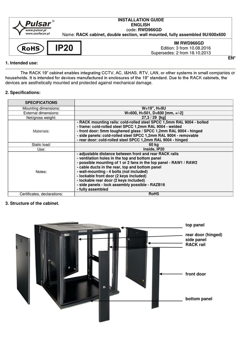
Pulsar RWD966GD User manual

Pulsar

Pulsar RWD966GD User manual

Pulsar AWO 350 User manual

Pulsar

Pulsar AWO 350 User manual

Pulsar AWO 620 User manual

Pulsar

Pulsar AWO 620 User manual

Pulsar AWO610 User manual

Pulsar

Pulsar AWO610 User manual

Pulsar ARADIN1 User manual

Pulsar

Pulsar ARADIN1 User manual

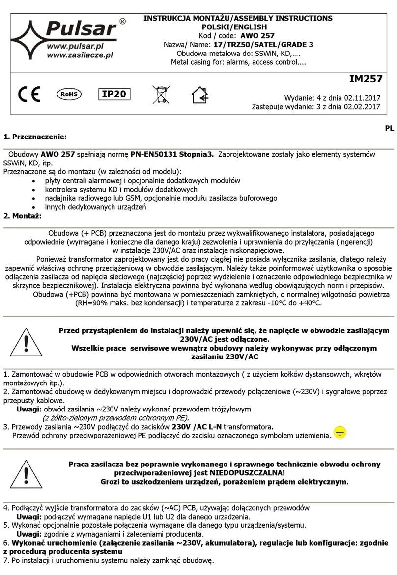
Pulsar AWO 257 User manual

Pulsar

Pulsar AWO 257 User manual

Pulsar AWO 200 User manual

Pulsar

Pulsar AWO 200 User manual

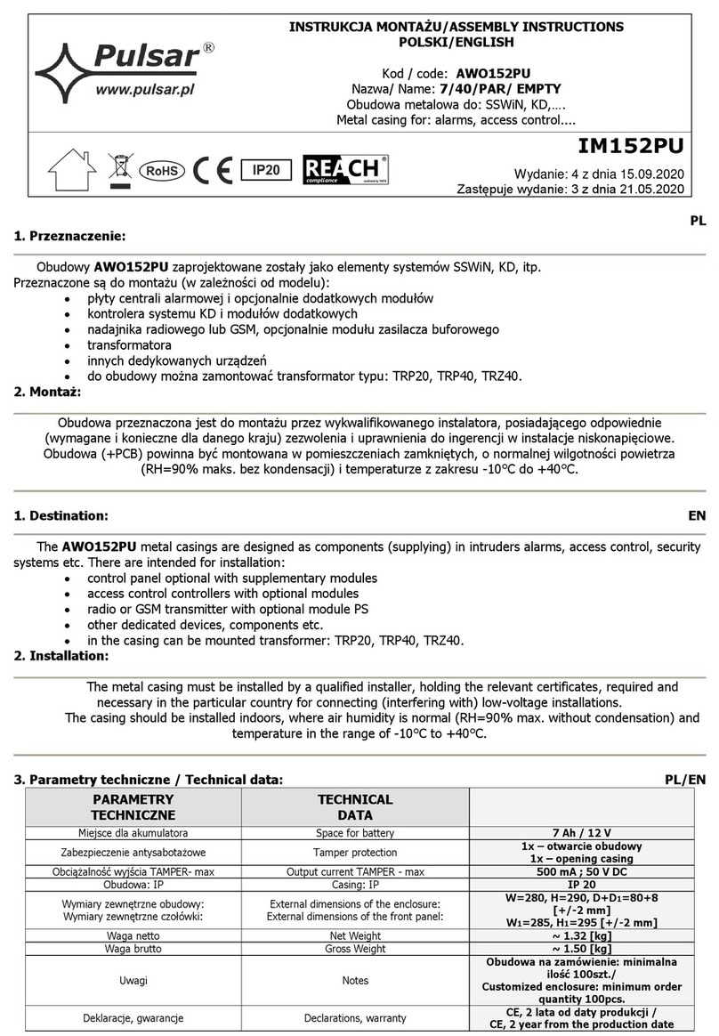
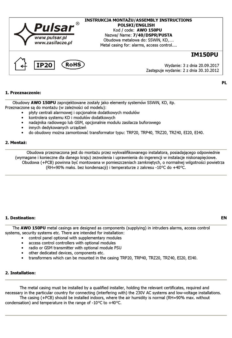
Pulsar AWO152PU User manual

Pulsar

Pulsar AWO152PU User manual

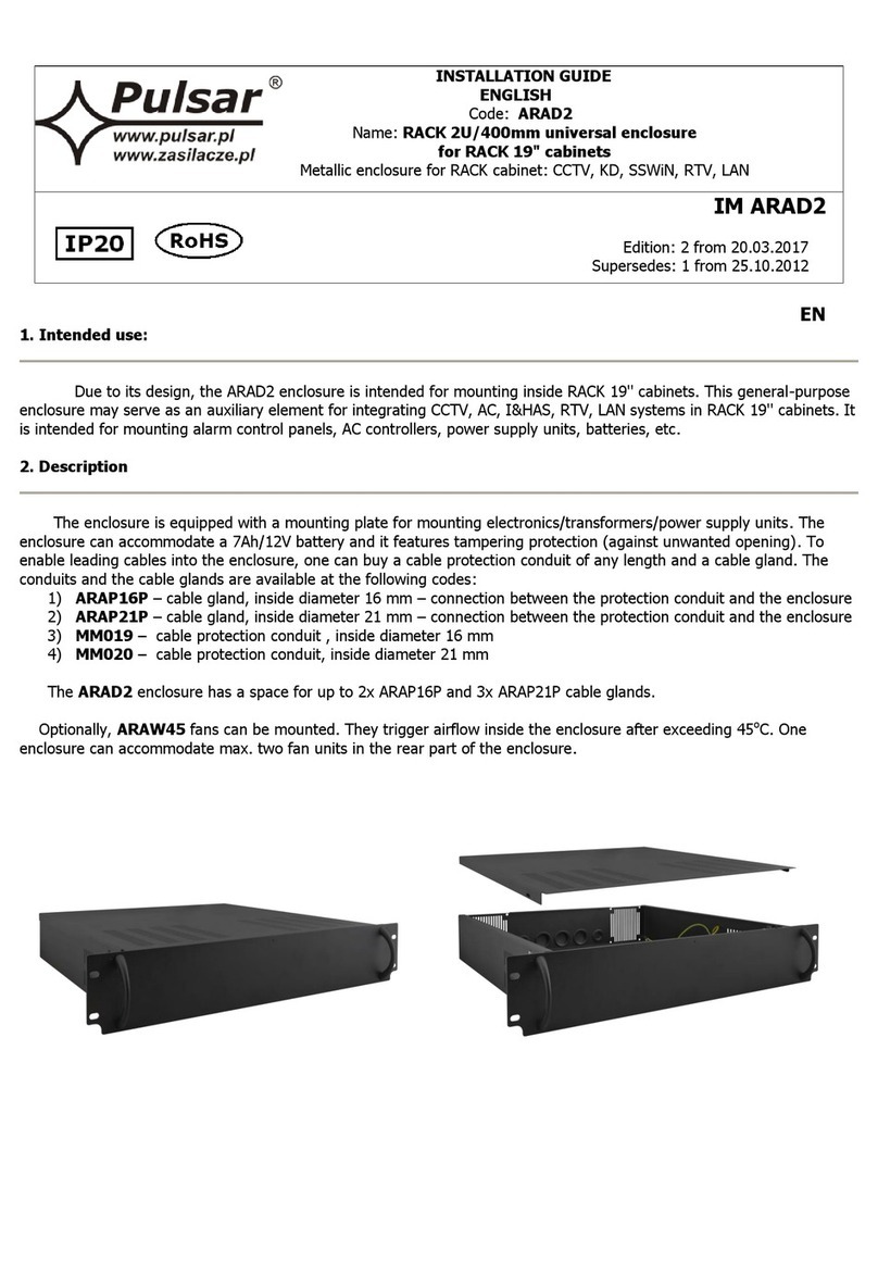
Pulsar ARAD4 User manual

Pulsar

Pulsar ARAD4 User manual

Pulsar AWO528 User manual

Pulsar

Pulsar AWO528 User manual

Pulsar 17/50/DSPR/PUSTA User manual

Pulsar

Pulsar 17/50/DSPR/PUSTA User manual

Pulsar AWZ637 User manual

Pulsar

Pulsar AWZ637 User manual

Pulsar AWO 363 User manual

Pulsar

Pulsar AWO 363 User manual

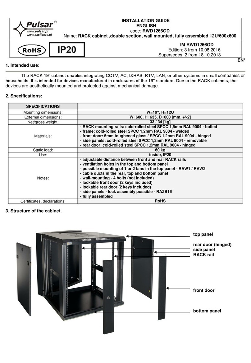
Pulsar RWD1266GD User manual

Pulsar

Pulsar RWD1266GD User manual

Pulsar 7/TRP20/SATEL User manual

Pulsar

Pulsar 7/TRP20/SATEL User manual

Pulsar AWO530 User manual

Pulsar

Pulsar AWO530 User manual

Pulsar 17/50/SATEL/PUSTA User manual

Pulsar

Pulsar 17/50/SATEL/PUSTA User manual

Pulsar RAWO7 User manual

Pulsar

Pulsar RAWO7 User manual

Pulsar AWO 200PU User manual

Pulsar

Pulsar AWO 200PU User manual

Pulsar 17/TRZ40/S-F User manual

Pulsar

Pulsar 17/TRZ40/S-F User manual

Popular Enclosure manuals by other brands

Antec Veris Fusion Remote Max Specification sheet

Antec

Antec Veris Fusion Remote Max Specification sheet

ENERMAX iVektor.Q ECA 3371 Series user manual

ENERMAX

ENERMAX iVektor.Q ECA 3371 Series user manual

Lindy 43095 user manual

Lindy

Lindy 43095 user manual

SICK C4000 Select operating instructions

SICK

SICK C4000 Select operating instructions

Geeek A60 PLUS installation guide

Geeek

Geeek A60 PLUS installation guide

OVE SYDNEY 48 installation manual

OVE

OVE SYDNEY 48 installation manual

SilentiumPC Armis AR5 Hardware installation

SilentiumPC

SilentiumPC Armis AR5 Hardware installation

MSI MPG SEKIRA 500X quick start guide

MSI

MSI MPG SEKIRA 500X quick start guide

Antec Dark fleet DF-10 user manual

Antec

Antec Dark fleet DF-10 user manual

Peavey DS 1502 Specifications

Peavey

Peavey DS 1502 Specifications

D-Link ShareCenter Pro DNS-1550-04 user manual

D-Link

D-Link ShareCenter Pro DNS-1550-04 user manual

Rosewill RX82-U(JBOD) user manual

Rosewill

Rosewill RX82-U(JBOD) user manual

QNAP SAS JBOD CLI 1.0 user guide

QNAP

QNAP SAS JBOD CLI 1.0 user guide

GAMDIAS Talos P1 Quick installation guide

GAMDIAS

GAMDIAS Talos P1 Quick installation guide

Auvs KR615 user manual

Auvs

Auvs KR615 user manual

Antec AR300 user manual

Antec

Antec AR300 user manual

CommScope FDH 3000 user manual

CommScope

CommScope FDH 3000 user manual

FS FHD-FWME4 quick start guide

FS

FS FHD-FWME4 quick start guide

manuals.online logo
manuals.online logoBrands
  • About & Mission
  • Contact us
  • Privacy Policy
  • Terms and Conditions

Copyright 2025 Manuals.Online. All Rights Reserved.

INSTRUKCJA MONTAŻU/ASSEMBLY INSTRUCTIONS
POLSKI/ENGLISH
Kod / Code: AWO520PU
Nazwa/ Name: 28/80/L-F/PUSTA
Obudowa metalowa do: SSWiN, KD,….
Metal casing for: alarms, access control....
IM520PU
Wydanie: 4 z dnia 26.11.2021
Zastępuje wydanie: 3 z dnia 18.10.2017
PL/EN
1. Przeznaczenie / Destination:
Obudowy AWO520PU zaprojektowane zostały, jako elementy systemów SSWiN, KD, itp.
Przeznaczone są do montażu (w zależności od modelu):
płyty centrali alarmowej i opcjonalnie dodatkowych modułów
kontrolera systemu KD i modułów dodatkowych
nadajnika radiowego lub GSM, opcjonalnie modułu zasilacza buforowego
innych dedykowanych urządzeń
do obudowy można zamontować transformator typu: TRP, TRZ.
możliwość zmiany kierunku otwierania drzwi lewa/prawa
drzwiczki posiadają przetłoczenie do wybicia pozwalające na montaż zamka MR008 (różny kod)
lub MR027 (ten sam kod).
Uwaga! Zamek nie znajduje się na wyposażeniu obudowy.
The AWO520PU metal casings are designed as components (supplying) in intruders alarms, access control systems,
security systems etc. There are intended for installation:
control panel optional with supplementary modules
access control controllers with optional modules
radio or GSM transmitter with optional module PSU
other dedicated devices, components etc.
transformers which can be mounted in the casing: TRP, TRZ.
left / right door opening
door has embossing to be knocked out allowing installation of lock MR008 (different code)
or MR027 (the same code)
Caution! Lock is not included.
2. Montaż / Installation:
Obudowa przeznaczona jest do montażu przez wykwalifikowanego instalatora, posiadającego odpowiednie
(wymagane i konieczne dla danego kraju) zezwolenia i uprawnienia do ingerencji w instalacje niskonapięciowe.
Obudowa (+PCB) powinna być montowana w pomieszczeniach zamkniętych, o normalnej wilgotności powietrza
(RH=90% maks. bez kondensacji) i temperaturze z zakresu -10°C do +40°C.
The metal casing must be installed by a qualified installer, holding the relevant certificates, required and necessary in
the particular country for connecting (interfering with) the 230 V AC systems and low-voltage installations.
The casing (+PCB) should be installed indoors, where the air humidity is normal (RH=90% max. without condensation)
and temperature in the range of -10°C to +40°C.
3. Parametry techniczne / Technical data:
PARAMETRY
TECHNICZNE
TECHNICAL
DATA
Miejsce dla akumulatora
Space for battery
28Ah/12 V
Zabezpieczenie antysabotażowe
Tamper protection
1x –otwarcie obudowy
1x –opening casing
Obciążalność wyjścia TAMPER- max
Output current TAMPER - max
500mA@50 V DC
Obudowa: IP
Casing: IP
IP 20
Temperatura pracy
Operating temperature
-10ºC÷40ºC
Wilgotność względna RH – max.
Relative humidity RH –max.
90 [%]
Wymiary zewnętrzne obudowy
Wymiary zewnętrzne kołnierza
Głębokość robocza
External dimensions of the enclosure
External dimensions of the flange
Working depth
W=350, H=400, D+D1=182+8 [-/+2] [mm]
W1=380, H1=450 [+/- 2mm]
D2=150 [+/-2 mm]
2
Wykonanie
Material description
Blacha DC01, grubość: 0,7mm
Zabezpieczenie antykorozyjne
Kolor: RAL 9003/
Sheet steel DC01, Thickness: 0,7mm, Protection
anticorrosion,
Color: RAL9003
Zastosowanie
Destination
Do wewnątrz / Indoor
Waga netto/brutto
Net/gross weight
5,604 / 6,107 [kg]
Gwarancja
Warranty
2 lata od daty produkcji
2 years from production date
3
Parametry techniczne transformatorów, które można zamontować w obudowie:
Technical data of the transformers, which can be mounted in the casing:
KOD
CODE
NAZWA
NAME
C
S
U
I
U1 lub U2 lub U3
U1 or U2 or U3
I1 lub I2 lub I3
I1 or I2 or I3
F
t
AWT050
TRP 20/16/18
PC/ABS
UL94 V-0
IP30
20VA
230 V
0,12 A
16 V lub 18 V
16 V or 18 V
1,2 A lub 1,0 A
1,2 A or 1,0 A
T 200mA/250 V
130oC
AWT053
TRP 20/12/14
PC/ABS
UL94 V-0
IP30
20VA
230 V
0,12 A
12 V lub 14 V
12 V or 14 V
1,6 A lub 1,4 A
1,6 A or 1,4 A
T 200mA/250 V
130oC
AWT150
TRP 40/16/18
PC/ABS
UL94 V-0
IP30
40VA
230 V
0,20 A
16 V lub 18 V
16 V or 18 V
2,2 A lub 2,0 A
2,2 A or 2,0 A
T 315mA/250 V
130oC
AWT500
TRP50/16/18/20
PC/ABS
UL94 V-0
IP30
50VA
230 V
0,25 A
16 V lub 18 V lub 20 V
16 V or 18 V or 20 V
3,0 A lub 2,8 A lub 2,5 A
3,0 A or 2,8 A or 2,5 A
T 500mA/250 V
130oC
AWT800
TRP80/16/18/20
PC/ABS
UL94 V-0
IP30
80VA
230 V
0,4 A
16 V lub 18 V lub 20 V
16 V or 18 V or 20 V
5,0 A lub 4,5 A lub 4,0 A
5,0 A or 4,5 A or 4,0 A
T 630mA/250 V
130OC
AWT824
TRP80/17/24/30
PC/ABS
UL94 V-0
IP30
80VA
230 V
0,4 A
17 V lub 24 V lub 30 V
17 V or 24 V or 30 V
4,7 A lub 3,3 A lub 2,7 A
4,7 A or 3,3 A or 2,7 A
T 630mA/250 V
130oC
AWT468
TRZ 40/16/18
PC/ABS
UL94 V-0
IP43
40VA
230 V
0,20 A
16 V lub 18 V
16 V or 18 V
2,2 A lub 2,0 A
2,2 A or 2,0 A
T 315mA/250 V
130oC
AWT682
TRZ60/18/20
PC/ABS
UL94 V-0
IP43
60VA
230 V
0,33 A
18 V lub 20 V
18 V or 20 V
3,3 A lub 3,0 A
3,3 A or 3,0 A
T 500mA/250 V
130oC
AWT
8161820
TRZ 80/16/18/20
PC/ABS
UL94 V-0
IP43
80VA
230 V
0,4 A
16 V lub 18 V lub 20 V
16 V or 18 V or 20 V
5,0 A lub 4,5 A lub 4,0 A
5,0 A or 4,5 A or 4,0 A
T 630mA/250 V
130oC
AWT
8172430
TRZ 80/17/24/30
PC/ABS
UL94 V-0
IP43
80VA
230 V
0,4 A
17 V lub 24 V lub 30 V
17 V or 24 V or 30 V
4,7 A lub 3,3 A lub 2,7 A
4,7 A or 3,3 A or 2,7 A
T 630mA/250 V
130oC
C –Obudowa transformatora / Transformer casing
S–Moc / Power rating
U–Napięcie zasilania / Supply voltage
I –Prąd pobierany przy nominalnym obciążeniu z sieci ~230V / Current draw at nominal load, from network ~230V
U1 lub/or U2 lub/or U3 –Napięcia wtórne / Secondary voltage
I1 lub/or I2 lub/or I3 –Nominalny prąd wyjściowy / Nominal output current
F–Bezpiecznik F w obwodzie pierwotnym transformatora / Fuse F in the primary windings of the transformer
t –Bezpiecznik termiczny 130oC niepowracalny / Non ressetable fuse 130oC
4. Centrale które można zamontować w tej obudowie / panels which can be mounted in the casing.
DSC:
Power Series Neo
Centrale / Alarm control panels:HS2016, HS2016-4, HS2032, HS2064, HS2128.
Moduły / Modules:HSM2300, HSM2204, HSM2208, HSM2108, PCL-422
Power Series
Centrale / Alarm control panels: PC1616, PC1832, PC1864.
Moduły / Modules:PC5320, PC5100, PC5108, PC4216, PC5200, PC5204, PC5400, IT-100.
Power Series Pro
Centrale / Alarm control panels: HS3032, HS3128, HS3248.
Moduły / Modules:HSM3408, HSM2108, HSM3204CX, HSM3350, AMX-400.
EBS:
Centrale / Alarm control panels:PX 202A
PARADOX:
Centrale / Alarm control panels:728 ULT, E55, 65, SP4000, SP5500, 6000, 7000, EV048, 192.
Moduły / Modules:ZX4, ZX8, ZX8SP, APR3- HUB2, PGM4.
PYRONIX:
Centrale / Alarm control panels:MATRIX 424, 6/816, 832, 832+
4
RISCO:
Centrale / Alarm control panels:PRO24, 116, 128, 140.
Moduły / Modules:RP296EPS
ROEL:
Centrale / Alarm control panels:SIGMA 6,12, CERBER
ROGER:
Centrale / Alarm control panels:PR402, CPR 32- SE
SATEL:
Centrale / Alarm control panels:Integra32, 24, 64, 128, 128+, 256+, Versa 5, 10, 15 Plus, IP, Perfecta 16, 32,
32 LTE –T 32, Micra, CA-10 P, CA-6 P, CA-5 P, CA-4 VP.
Moduły / Modules:CA-64 PTSA, CA-10 E, ETHM-1 Plus, ETHM-2,GSM-X, GSM-X LTE, INT-ADR, INT-AV, INT-E, INT-FI, INT-GSM,
INT-KNX-2, INT-O, INT-PP, INT-R, INT-RS Plus, INT-VG, INT-VMG, MST-1, ACCO-NT, ACCO-KP-PS, ACCO-KPWG-PS.
TELMOR:
Centrale / Alarm control panels:TCA-824, TEX800
Dokumentacja informuje, jakie urządzenia mogą być instalowane w danej obudowie. Nie określa, ile różnych
urządzeń można zainstalować w jednej obudowie. Ilość zamontowanych urządzeń zależna jest od ich wielkości i
rozmieszczenia.
Documentation shows which devices can be installed in a given enclosure. It does not define how many different
devices can be installed in one enclosure. Number of installed devices depends on their size and arrangement.
OZNAKOWANIE WEEE
Zużytego sprzętu elektrycznego i elektronicznego nie wolno wyrzucać razem ze zwykłymi domowymi
odpadami. Według dyrektywy WEEE obowiązującej w UE dla zużytego sprzętu elektrycznego i elektronicznego
należy stosować oddzielne sposoby utylizacji.
W Polsce zgodnie z przepisami o zużytym sprzęcie elektrycznym i elektronicznym zabronione jest umieszczanie łącznie z
innymi odpadami zużytego sprzętu oznakowanego symbolem przekreślonego kosza. Użytkownik, który zamierza się pozbyć
tego produktu, jest obowiązany do oddania ww. do punktu zbierania zużytego sprzętu. Punkty zbierania prowadzone są m. in.
przez sprzedawców hurtowych i detalicznych tego sprzętu oraz gminne jednostki organizacyjne prowadzące działalność w
zakresie odbierania odpadów. Prawidłowa realizacja tych obowiązków ma znaczenie zwłaszcza w przypadku, gdy w zużytym
sprzęcie znajdują się składniki niebezpieczne, które mają negatywny wpływ na środowisko i zdrowie ludzi.
WEEE MARK
The waste electric and electronic products do not mix with general household waste. There is separate collection system for
used electric and electronic products in accordance with legislation under the WEEE Directive and is effective only with EU.
Ogólne warunki gwarancji
Ogólne warunki gwarancji dostępne na stronie www.pulsar.pl
ZOBACZ
PRODUCENT / PRODUCER
Pulsar sp. j.
Siedlec 150, 32-744 Łapczyca, Poland
Tel. (+48) 14-610-19-40, Fax. (+48) 14-610-19-50
e-mail: biu[email protected], sal[email protected]
http:// www.pulsar.pl, www.zasilacze.pl