PULSEEIGHT P8-HDBT2-U-FFMJ108-S Specification sheet

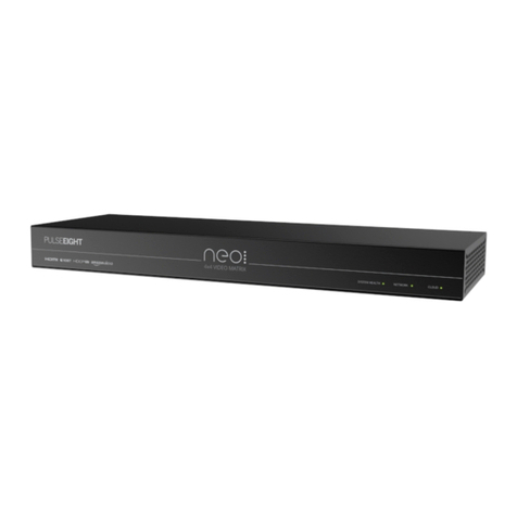
neo:XMRVideo Matrix
Product User Guide

Table of Content
"Introduction" on the next page
"Product Description" on page4
"Safety Precaution" on page6
"Panel" on page7
"Cabling" on page10
"Setup" on page12
"Web Interface Setup" on page21
"Monitoring Portal" on page39
"EDIDManagement" on page43
"Concept Wiring Guideline" on page50
"Driver Integration" on page52
"Audio Routing" on page63
"Troubleshooting" on page69
"Specification" on page72
"Additional" on page76
"Firmware Updates" on page74
"Warranty Procedure" on page77

Introduction
NEO:XMR DESIGNED FOR BINARY BY PULSE-EIGHT
P8-HDBT2-U-FFMJ108-S
KEY FEATURES:
lUltra HD 4K/60Hz 4:4:4 (8bit) Video Transmission
lFull HDCP 2.3 Support
l6x HDMI Inputs
l6x HDBaseT Class C + DSC Outputs
l2x HDMI Outputs
l8x Audio Output Zones
l4x Audio Input Zones
lAudio Return Channel
lAudio Breakout of Input Sources
lAutomatic EDID Management
lIncludes user-friendly WebUI control access
lEasy integration with third-party control systems

Product Description
The neo:XMR Video & Audio Matrix has it all - with both audio and video inputs and video and audio
outputs. Featuring 6 HDMI inputs, 6 HDBaseT Outputs and 2 HDMI outputs alongside 8 audio output
zones (with the options of Stereo L/R, Optical and Digital Coax) and 4 audio input zones (with the option
of Optical and Digital Coax).
The neo:XMR goes the distance, supporting full 4K/60, 4:4:4, 8bit or 4K/60 4:2:2, 12bit up to 100 meters
(320 feet), with audio breakout, Dolby Digital compliance, and multiple video control methods.
IN THE BOX (KIT):
l1x neo:XMR Chassis
lRack Mounting Kit
lPower Cord
lPhoenix Connectors
Note: The items listed above comes in a kit. Our customers might receive a different inventory
depending on their purchase so please check with the installer or Pulse-Eight representative.

COMPATIBLE DEVICES
HDBaseT Receiver
HDBaseT receiver is required to function and sold separately.
lneo:Ultra Receiver (P8-HDBT2-U-RX-S)
lneo:UltraSR Receiver (P8-HDBT2-L-RX-S)
IRReceiver
IR receiver is required for additional IR functions and sold separately.
List of compatible IR receiver:
lEpisode Electronic Tabletop Plasma/LED-Proof IR Sensor with LED Feedback (EE-IR-RCVR-TT)
lEpisode Electronics Surface Mount Plasma/LED-Proof IR Receiver with LED Feedback (EE-IR-
RCVR-SM)
IRFlasher
IR transmitter is required for additional IR functions and sold separately.
List of compatible IR transmitters:
lEpisode Electronics IR Flasher with LED Feedback (IRF-1)
lEpisode Electronics IR Flasher with LED Feedback (IRF-2)

Safety Precaution
SAFETY PRECAUTION
Please read instructions before attempting to install or operate this equipment.
Please keep the following in mind as you unpack and install this equipment:
lThis video matrix uses a 12 V board for use with 12 V IR transmitter and receiver. These are not
compatible with 5 V video matrixes. Mixing and matching them could cause irreparable damage.
Please see the IR RECEIVER & TRANSMITTER under Product Description for compatible
transmitters and receivers.
lAlways follow basic safety precautions to reduce the risk of fire, electrical shock, and injury.
lTo prevent fire or shock hazard, do not expose the unit to rain, moisture or install this product near
water.
lNever spill liquid of any kind on or into this product.
lWhere possible, install the matrix towards the top of the rack to avoid the unit overheating.
lOnly use the supplied IEC cable.
lNever push any objects into this product through any openings or empty slots in the unit as you
may damage parts inside.
lDo not allow anything to rest on the power cabling and avoid putting weight of any kind on it.
lTo protect the unit from overheating do not block any vents or openings in the unit housing that
provides ventilation. Allow sufficient space for air to circulate around the unit.
Ventilation
It’s important when installing a Pulse-Eight product: keep the products ventilated.
Any electronic equipment will generate heat. A well-ventilated area helps to disperse the heat. If placed
in a poorly ventilated area, your equipment may heat up and cause minor irreparable damage to the
circuitries. Allowing systems to run for prolonged periods under high temperatures will break down
circuitry and chipset. It also applies if the device is left in the path of direct sunlight or near any heat
source.
Dust tends to accumulate and will disrupt the fan and electronics system. Dust particles contain various
compositions like water, oil and other minerals or chemicals. Having them in your electronic device can
sometimes cause a signal error or degradation to the internal chips and circuitries. Because we cannot
accurately predict how or when they can affect your device, we highly recommend that you keep Pulse-
Eight products not only in a well-ventilated area but also as clean as possible.
In some cases, insects or reptiles can make nests near or inside the electronic casing. Whilst we design
our products to maximise the protection of internal electronics, please be aware that insects and reptiles
are drawn to these types of habitats. In the unlikely event, this does happen, this will lead to poor
ventilation inside the unit, and it will be unable to disperse heat.
Finally, whenever possible, do not stack audio and video matrixes together. Leave enough space in
between each unit in order to provide good airflow.

Panel
NEO:XMR VIDEO MATRIX
P8-HDBT2-U-FFMJ108-S
A. System Health LED: Indicates whether matrix is turned ON (green), or whether there is an issue
present (red).
B. Network LED: Indicates the matrix is connected to the internet through its network link (green) or if
there is an issue (red). For further LED values please see the troubleshooting section.
C. Cloud LED: Indicates the matrix is able to connect to the Pulse-Eight Remote Monitoring Portal
(green) if there is an issue (red).
D. Power Connector: Power connector with OFF/ON switch. Use supplied cord to connect the power.
E. IR Receiver and Transmitter Ports: Connect as required. The IR Out port is to be used to connect
input devices using the supplied IR Emitters. The IRports support both 5V and 12V, please refer to
Web Interface Setup on switching between the modes.

F. RS232 Phoenix Ports: Ground = Zero volts. TX is signal coming out of matrix (from remote device)
RX is signal going into matrix (to remote device).
G. Audio Outputs: Analogue, Optical and Digital Coax options for Audio Breakouts.
H. HDBaseT Outputs: Connect the appropriate Cat5e or higher-grade cable to each output. These
cables should then be connected to a neo Receiver at each Sink device. (TV/Amplifier etc.).
I. HDMI Inputs: Connect the appropriate high speed HDMI cable to each input. These cables should
then be connected to the Source device. (Blu-ray player etc.)
J. Reset: Factory reset - please use only when instructed by our customer service team.
K. Ethernet: Connect to network - required for connection to Web Interface, Third Party Control and
Cloud Remote Monitoring Portal.
L. Audio Inputs: Optical and Digital Coax options for connecting audio only source devices.
M. HDMI IR In: Connect as required. The HDMI IR In ports are to be used to return IR back to the
matrix using an P8-IR-Optocable.
N. HDMI Outputs: Connect the appropriate high speed HDMI cable to each output. These cables
should then be directly connected to each Sink device. (TV/Amplifier etc.)

NEO:ULTRA RECEIVER
P8-HDBT2-U-RX-S
A. IR Activity Indicator: The LED will flash when an IR signal is being received.
B. IR Flasher (TX): Can be used for bi-directional IR to send IR data back to the matrix.
C. IR Receiver (RX): Connect the IR Receiver to this port and place the IR bud on the underside of the
sink device (i.e., TV).
D. HDBaseT Input: Connect the appropriate Cat5e or higher-grade cable to each the input of the
receiver, these cables should then be connected to one of the HDBaseT outputs on the matrix. The
LEDs will illuminate to indicate a link and power is being received.
E. HDMI Output: Connect the appropriate high speed HDMI cable and connect to the sink device.
F. RS232: Connect via 3.5mm Adapter (not included) for RS232 passthrough.
G. Ethernet: Optional connections for using ethernet passthrough.

Cabling
WHAT IS THE BEST TYPE OF CABLE TO USE?
Pulse-Eight products use HDBaseT standard that utilises regular Cat cables. Typically, the minimum
cable use on a neo system is Cat5e but you could increase the range and bandwidth by using higher tier
cables such as Cat6, Cat6A & Cat7 which have stricter shielding requirement and therefore reduces the
data loss between data pairs.
We highly discourage patch cabling as this might degrade the signal. Whenever possible, use a long,
single high-quality cable for each HDBaseT port as this allows the system to function at its best peak
efficiency.
We do not recommend the use of pre-made leads unless you are certain of the correct specs (i.e., solid
core 568B), the use of lower quality cables will lead to signal degradation and quality of the
transmission.
Please note Copper Clad Aluminium (CCA) cables are not supported. Due to the inherent properties of a
CCA, this will cause an HDBaseT performance issue.
SHIELDED CABLES
If you prefer shielded FTP cables, please ensure compatible shielded features are used such as
grounding & termination. A badly terminated cable can cause interference instead of eliminating it.
CABLING BEST PRACTICE
Our recommended and best practice policy is to use a straight cable directly from the Pulse-Eight matrix
to the receiver. This will ensure the best quality of signal and achieve maximum distance. You can find
further information on "HDBaseT Best Practices" on the HDBaseT Alliance website.
WALL PLATES & PATCH PANELS
If the patch panels are terminated correctly, there is minimal loss of distance. The use of wall plates and
patch panels, however, has the potential to cause increased resistance on the cable if not done
correctly, introducing pinch points for signal transmission, and could reduce advertised transmission
lengths. Instead of using RJ45 wall plates, you can use brush plates to maintain the neat finish.

CONNECTION TERMINATION
Whenever possible, use full plastic encasement. We do not recommend metal ones to avoid grounding
leaks to Pulse-Eight products. Terminate the cabling using RJ45 connectors to the 568B wiring
standard. (See diagram)
IMPORTANT: Please note that local building regulations may apply to the installation of
cabling in properties. It is important to check building regulations to guarantee that you
are in accordance with the laws of your territory.
IRFLASHER &RECEIVER
The neo:X+ (P8-HDBT2-U-FFMJ1210-S), neo:XMR (P8-HDBT2-U-FFMJ108-S) & neo:XSR (P8-
HDBT2-L-FFMJ66-S) uses a 12 V powered IR board designed specifically to work with 12 V IR
flasher/receiver.
See Product Description for compatible IR receiver and flasher.
Do not mix and match 12 V and 5 V IR receiver/flasher for different video matrixes/extenders as they
might cause irreparable damage to the board.

Setup
INSTALLING IN A RACK
1. Attach the rack ears to the front sides of the matrix using the provided screws.
2. Install into rack and connect cabling according to mode of operation – as described below.
WARNING: To prevent damage, it is important to ensure adequate ventilation space on the sides of the
matrix, especially on the ventilation openings on the side of the product enclosure.
CONNECTING THE VIDEO INPUTS
3. Connect HDMI cables from your video sources (e.g. Blu-Ray player) to the HDMI inputs of the matrix.
Note: It is recommended, for ease of setup, to connect devices from Input 1 to Input 8 first..
4. Connect the compatible IR Flasher (Emitter/Transmitter) over the source device's IR window and
attach to the ‘Flasher' port.
Note: Ensure that the IR Emitter is connected to the same zone as the source device's HDMI input (i.e
HDMI input 3 and IR 3)

CONNECTING THE HDBASET VIDEO OUTPUT
5. Connect the appropriate Cat5e or higher grade cable to each HDBaseT output port you require.
Note: It is recommended, for ease of setup, to connect devices from Output 1 to Output 8, although this
is not necessary.
6. Complete the connection by attaching the other end of the Cat cable to a supplied neo Receiver's
'HDBaseT In' port. The receiver should be situated at the output end (i.e. TV).

7. Connect HDMIOut to the output screen (i.e. TV).
8. Attach the compatible IR receiver into the IR Receiver port and attach the bud to the underside of the
sink device with the smallest end forward, as per the diagram.
Note: Use only neo:Ultra Receiver (P8-HDBT2-U-RX-S) or neo:UltraSR Receiver (P8-HDBT2-L-RX-S)
as they provide the same compatible 12 V IR receiver/transmitter to the video matrix.
Note: Please make sure to use a compatible 12 V IR receiver/flasher on this product. Please refer to IR
FLASHER & RECEIVER under Cabling and Compatible Devices under Product Description.

CONNECTING THE HDMI VIDEO OUTPUTS
9. For Output ports 9 and 10, connect sink devices directly via high speed HDMI cables.
Note: Can also be used in conjunction with a neo HDMI Extender Set (sold separately) for reaching
further distances.
CONNECTING THE AUDIO INPUTS
10. The neo:XMR features 4 zones of independent audio inputs. Connect your audio source device
directly to either the digital coax or optical ports (Inputs 9-12).

CONNECTING THE AUDIO OUTPUTS
11. If you wish to use the Audio outputs, please connect cables to the relevant output - each output zone
features Analogue, Optical and Digital Coax options.
Note: The audio outputs allow matrixing, please refer to Web Interface Setup to find out more.
CONNECTING TO NETWORK
12. Connect a standard Ethernet cable (Category 5e/6/7) from the matrix's 'Ethernet' port to your router
or network switch. Crossover cables are not supported.
Note: Network connection is required for supporting full control/remote monitoring features of the
product.
TURNING ON THE MATRIX
13. Insert the supplied power cord and plug into the AC mains.
14. Turn ON the power switch.
15. As it powers ON, the front panel LEDs (System Health, Network, Cloud) will illuminate momentarily
before it begins its initialisation sequence.
Note: The initialisation process takes between 20 seconds and up to 2 minutes. However, it is possible
that a firmware update may be available the first time the unit is powered ON - in this instance the matrix
may take longer to initialize. If both the System Health and Network LEDs flash (orange/green) quickly
together then a firmware update is being applied. Please wait and do not disconnect the power until this
update has completed.

16. Once initialisation has been completed, the System Health, Network and Cloud LEDs should all
appear ON (green).
17. You are now ready to setup the matrix using the web interface. Please follow the steps in the
'Connecting to Admin Web Interface' section.
18. Using a computer connected to same router/network, access and login to the Web Interface by
visiting www.gotomymatrix.com in your web browser.
19. Activate administrative rights by clicking on the Cloud Connection tab on the left hand nav, then
click on the '[Admin]' link at the foot of the page.

20. Whilst on the Cloud Connection page, insert your Installer ID into the box and save changes - this
will enable the matrix to be linked to your monitoring account. If you have not set up an installer ID,
please contact Snap One support to obtain the password. Alternatively, please refer to the 'Quick
StarGuide' for further instructions.
21. Within this interface are many setup options - please refer to the Web Interface Setup Guide for
further details.

LED STATUS
22. Check the LEDs on the HDBaseT ports of the Receiver and Transmitter to ensure correct installation
and connection:
lThe Yellow LED will illuminate when connected to a video link.
lThe Green LED will illuminate when the device is connected to the power supply.

IR RECEIVER &TRANSMITTER PORTS
1. The IR ports above the HDBaseT outputs work as follows:
RECEIVER is an IR input signal coming into the matrix that is intended to be sent to another room over
the HDBT port below it – i.e., it is a one-to-one extension from matrix to attached HDBT receiver’s IR-TX
port.
You can connect to these ports either an Episode IR Receiver or directly to a Control4 EA controller.
IMPORTANT: make sure the 12 V for the port is disabled (see web interface section) before connecting
directly to a Control4 EA controller!
FLASHER port is an output signal connected to IR blasters controlling the sources on the rack. The
original IR signal can come from any connected HDBaseT Receiver IR input and the signal is then
routed to/blasted out the FLASHER port according to the video that you are watching – e.g., if you are
routing video from the source connected to HDMI In #2 on to display connected to HDBT out # 5, then
any IR signal received over the HDBT port #5 will be blasted out the matrix’s IR FLASHER port #2.
2. The IR ports above the HDMI outputs are a little different (hence why they are labelled differently):
INPUT is designed to receive IR signal from an external HDBaseT set directly connected the HDMI
output. This input signal is equivalent to the IR RX on a HDBaseT receiver side. This signal will be
routed to the FLASHER port you’re watching on this HDMI output. E.g., on the neo:X+, if you are routing
video from HDMI input #1 on to HDMI output # 9, then any IR INPUT signal on output #9 will be routed to
IR FLASHER port # 1.
NOTE: If a display is connected locally (i.e., there is no extender set connected to HDMI output) then this
IR INPUT port should generally not be required in an installation.
OUTPUT is there to support IP to IR blasting to the attached TV, if in use in the installation.
Table of contents
Other PULSEEIGHT Extender manuals

PULSEEIGHT
PULSEEIGHT HDBaseT Lite User manual

PULSEEIGHT
PULSEEIGHT P8-HDBT2-P-EXSET User manual

PULSEEIGHT
PULSEEIGHT P8-AE-CAT-EXSET User manual

PULSEEIGHT
PULSEEIGHT P8-AE-CAT-EXSET User manual

PULSEEIGHT
PULSEEIGHT neo P8-HDBT2-U-EXSET User manual

PULSEEIGHT
PULSEEIGHT neo 4*4 Video Matrix Specification sheet

PULSEEIGHT
PULSEEIGHT P8-NEOTAP User manual

PULSEEIGHT
PULSEEIGHT P8-HDBT-L-EXSET User manual

PULSEEIGHT
PULSEEIGHT neo LITE HDMI EXTENDER User manual