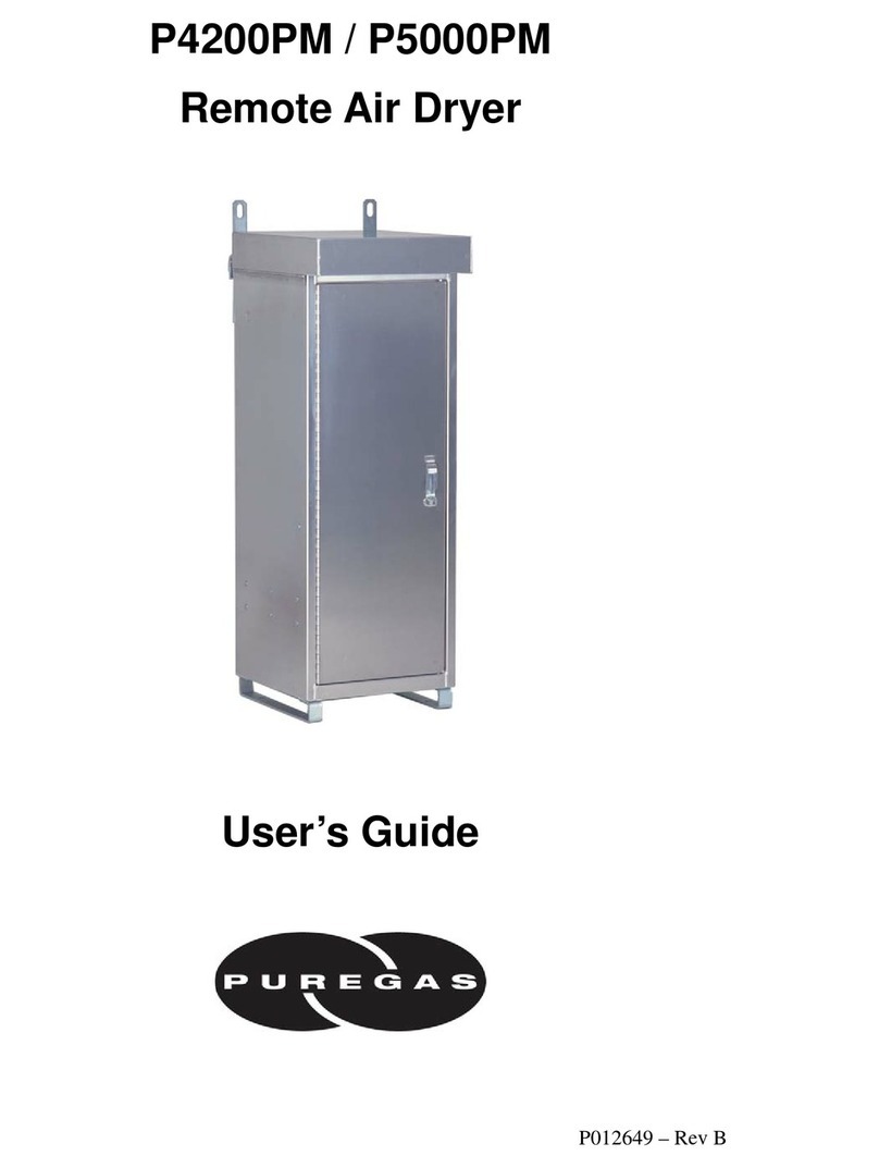
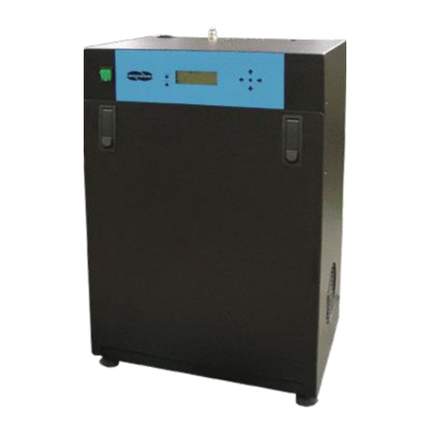
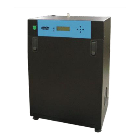
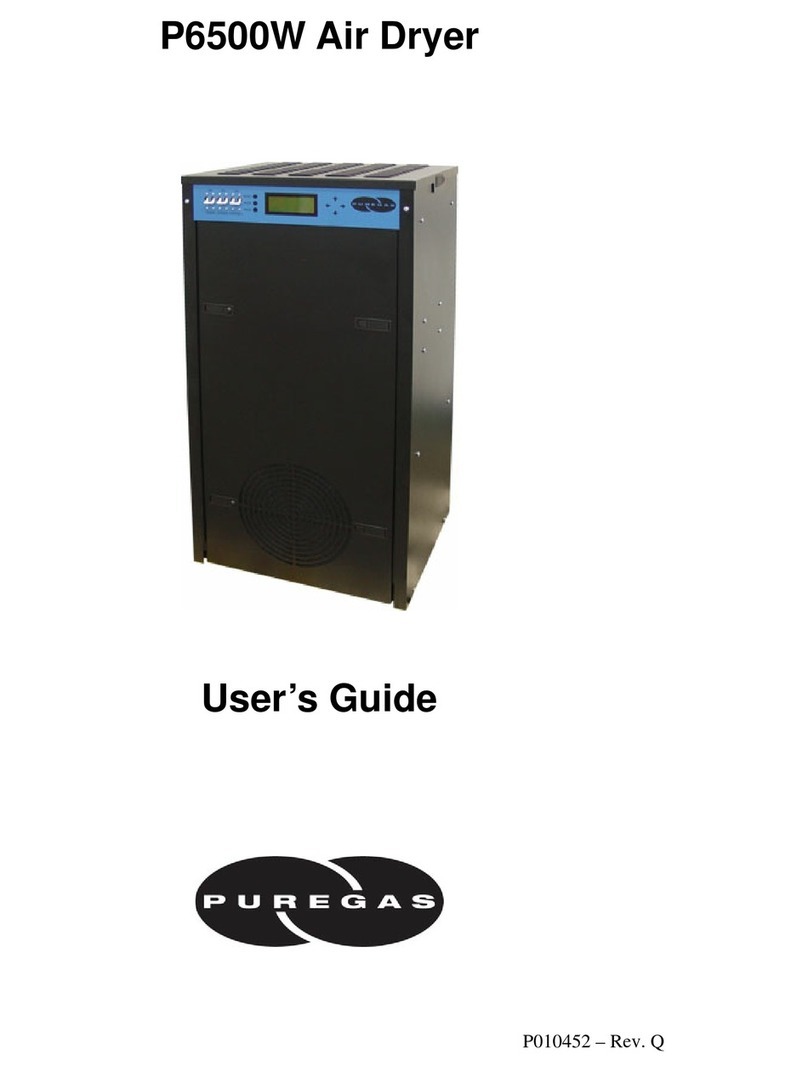
Puregas MDH Series User manual

P012547 REV D
MDH Series Air Dryer
User’s Guide
Models covered:
MDH1 MDH2 MDH3 MDH4 MDH5 MDH6


PUREGAS, LLC MDH Series User’s Guide
Page 3 of 36 P012547 REV D
1. Welcome & Congratulations
Congratulations on your purchase of a new PUREGAS MDH SERIES AIR DRYER!
We here at PUREGAS are very proud of our products. We are committed to providing
you with the best value and service possible.
We are sure that you will be satisfied with your new unit and would like to thank you for
choosing PUREGAS for your air dryer requirements. We also hope that you will continue
to choose us for your future Compressed Air Treatment and related products purchases.
For information about this and other PUREGAS products, please visit us on the web at
www.puregas.com
2. Introduction
PLEASE READ THIS USER’S GUIDE THOROUGHLY AND SAVE FOR
FUTURE REFERENCE.
This User’s Guide is provided for the benefit of our customers and contains information
and direction specific to the PUREGAS MDH SERIES AIR DRYER. It will cover topics
including: safety, specifications, installation, testing, maintenance, and troubleshooting
issues. Observation and compliance with this User’s Guide will ensure the maximum life
and efficiency of your air dryer.
This User’s Guide should be read thoroughly prior to installing, operating, or servicing
the air dryer in order to become familiar with the recommended procedures. This will
minimize the possibility of personal injury or damage to the dryer due to improper
operation or handling.

PUREGAS, LLC MDH Series User’s Guide
Page 4 of 36 P012547 REV D
3. Table of Contents
1. Welcome & Congratulations .......................... 3
2. Introduction ..................................................... 3
3. Table of Contents............................................. 4
4. Safety & Warning Information...................... 5
5. Overview & Specifications.............................. 6
5.1 Product Description.................................... 6
5.2 Key Features............................................... 6
5.3 MDH Series Air Dryer Models................... 6
5.4 Technical Specifications............................. 7
6. Installing Your Air Dryer............................... 8
6.1 Safety & Warning Information................... 8
6.2 Before You Begin....................................... 9
6.3 Included Contents..................................... 10
6.4 Required Tools and Materials................... 10
6.5 Installation Steps....................................... 11
6.6 Installation Checklist................................ 14
7. Registering Your MDH Series Air Dryer.... 15
8. Testing Your Air Dryer................................. 16
8.1 Safety & Warning Information................. 16
8.2 Testing Consistent Dryer Cycling............. 17
8.3 Measuring Incoming Voltage ................... 18
8.4 Measuring 4 Way Solenoid Voltage......... 19
8.5 Visually Verify Cycle Timer .................... 20
8.6 Test for Purge Muffler Restriction............ 21
8.7 Testing Air Fittings & Hoses for Leaks.... 22
9. Maintaining Your Dryer............................... 23
9.1 Safety & Warning Information................. 23
9.2 Maintenance Log Sheet ............................ 24
10. Replacement Parts & Accessories .............. 25
10.1 Parts........................................................ 25
10.2 Parts Continued....................................... 26
10.3 Accessories for Your Air Dryer.............. 27
10.4 Ordering Parts from PUREGAS............. 28
11. Service & Repair.......................................... 28
11.1 Services Offered at Puregas’ Facility...... 28
11.2 Initiating a Service Transaction .............. 29
12. Troubleshooting Your Air Dryer ............... 29
12.1 Before You Call PUREGAS................... 29
12.2 Safety & Warning Information ............... 30
12.3 Restricted Pressure or Flow .................... 30
12.4 Excessive Purge...................................... 31
12.5 Delivers Wet Air..................................... 31
12.6 Contacting PUREGAS Technical
Support............................................................ 32
13. Appendix ...................................................... 33
13.1 Model Number Coding........................... 33
13.2 Wiring Diagram...................................... 33
14. Limited Warranty Agreement.................... 34
Registration Reminder.................................... 34
15. Contacting PUREGAS ................................ 35
15.1 General.................................................... 35
15.2 Sales........................................................ 35
15.3 Service .................................................... 35
15.4 Technical Support................................... 35
16. Maintenance Log Sheet............................... 36
17. Notes.............................................................. 36

PUREGAS, LLC MDH Series User’s Guide
Page 5 of 36 P012547 REV D
4. Safety & Warning Information
This section contains general information about safety and warning points to consider and
adhere to during installation and maintenance of your air dryer. PLEASE READ THIS
SECTION BEFORE PERFORMING ANY OPERATION OR PROCEDURE ON YOUR
AIR DRYER.
Additional warnings specific to an operation or procedure will also be presented
throughout the following sections. These will include the symbol as well as a label of
“WARNING!”, “CAUTION!”, or “IMPORTANT!”. Please be sure to pay close
attention for these warnings and read them as you encounter them.
IMPORTANT!
Performing procedures not described in this User’s Guide MAY VOID
THE WARRANTY.
IMPORTANT!
Appropriate inlet filtration is MANDATORY and outlet filtration is
recommended for all applications.
IMPORTANT!
Each air dryer is sized for specific operating conditions. For
OPTIMUM performance, the maximum available operating pressure
should be maintained across the unit. Any pressure reduction or flow
control should be done downstream of the unit. Depending on the
magnitude of the change, the size of the desiccant chambers or orifice
may need to be changed.

PUREGAS, LLC MDH Series User’s Guide
Page 6 of 36 P012547 REV D
5. Overview & Specifications
5.1 Product Description
The MDH SERIES AIR DRYER from PUREGAS is a compact, regenerative
desiccant air dryer designed to dry compressed air to a standard pressure dew point
(PDP) of -40°F. Optional performance of -100°F atmospheric dew point (ADP) can
be achieved. The pressure-swing adsorption (PSA) process used is fully automatic
and will remain consistent with minimal required periodic maintenance.
5.2 Key Features
•Ultra dry air to better than -40°F PDP
•Continuous self-regenerative operation
•Outlet flow capacities of 0.3 to 2.4 SCFM at 100 PSIG
•Operating pressures of 30 to 120 PSIG
•Miniature design sized for fractional horsepower air compressor
•Low power requirements (6 watts)
•Ideal for OEM and point-of-use applications
5.3 MDH Series Air Dryer Models
Notes:
1. Flow capacities in SCFM shown are for standard units operated at 100 PSIG and outlet dew point
of -40°F PDP.
2. Inlet and outlet flow capacities will be greater at higher pressures and lower at lower pressures.
Consult factory for other conditions.
3. Standard compressed air inlet conditions are 100°F saturated.
Model
Inlet Flow
Purge Flow
Outlet Flow
MDH1
0.40
0.10
0.30
MDH2
0.80
0.20
0.60
MDH3
1.10
0.27
0.83
MDH4
1.60
0.40
1.20
MDH5
2.40
0.60
1.80
MDH6
3.20
0.80
2.40

PUREGAS, LLC MDH Series User’s Guide
Page 7 of 36 P012547 REV D
5.4 Technical Specifications
Dimensions MDH1
MDH2
MDH3
MDH4
MDH5
MDH6
7.0” H x 3.5” W x 3.3” D
10.3” H x 3.5” W x 3.3” D
8.8” H x 4.0” W x 3.5” D
10.1” H x 4.0” W x 3.5” D
9.5” H x 5.0” W x 3.8” D
11.5” H x 5.0” W x 3.8” D
Voltage Requirements
115 VAC, 1 Phase 50/60 Hz
230 VAC, 1 Phase 50/60 Hz
12 VDC
24 VDC
48 VDC
Power
6 Watts
Electrical Rating
NEMA 1
Operating Ambient
Temperature Range
33to 120F (0.5to 49C)
Inlet Temperature
≤ 70°F Recommended
120°F Maximum
Maximum Inlet Pressure
120 PSIG
Cycle Timer
Solid State with memory
Purge Cycle
60 seconds per side continuous
Separation Media
4A50 Molecular Sieve
Noise Level
<90 dBA
Inlet/Outlet Connections
MDH1-MDH4
MDH5-MDH6
1/8” NPT Female
1/4” NPT Female

PUREGAS, LLC MDH Series User’s Guide
Page 8 of 36 P012547 REV D
6. Installing Your Air Dryer
6.1 Safety & Warning Information
WARNING!
Extreme care should be exercised to avoid contact with live
electrical circuits. Many procedures performed during
installation, and testing of this air dryer require the equipment to be
running, creating a situation for potential electrical shock. It is
highly recommended that you remove all jewelry before
performing any procedures.
CAUTION!
Proper Installation & Maintenance as outlined in this User’s Guide
is extremely important to ensure the reliability and longevity of the
equipment as well as prevent damage or personal injury.
CAUTION!
Incoming power to dryer must be one of the following:
•115 VAC, 1 Phase, 50/60 Hz
•230 VAC, 1 Phase, 50/60 Hz
•12 VDC
•24 VDC
•48 VDC
CAUTION!
Do NOT exceed the SCFM flow capacity of the air dryer. Be aware
of what your unit is rated for before installation.

PUREGAS, LLC MDH Series User’s Guide
Page 9 of 36 P012547 REV D
6.2 Before You Begin
6.2.1 Carefully inspect the unit, including the shipping box as well as the air
dryer, for ANY DAMAGE CAUSED BY SHIPPING. If any shipping
damage is detected, it is important to file a claim with the shipping
company prior to continuing the installation procedures.
6.2.2 Read the entire Installing Your Air Dryer section to familiarize yourself
with the components and procedures before performing the installation.
6.2.3 Verify the installation location of the air dryer:
6.2.3.1 Ambient temperature is between 33° and 120°F
NOTE: Temperatures above 120°F will decrease component lifespan.
6.2.3.2 Meets one of the following power requirements:
•115 VAC, 1 Phase, 50/60 Hz
•230 VAC, 1 Phase, 50/60 Hz
•12 VDC
•24 VDC
•48 VDC

PUREGAS, LLC MDH Series User’s Guide
Page 10 of 36 P012547 REV D
6.3 Included Contents
(1) MDH Series Air Dryer
(1) User’s Guide (not shown)
6.4 Required Tools and Materials
•Power Cord (varies on voltage of unit)
•Needle nose pliers
•Mounting hardware
•Drill
•Drill bit (varies on mounting hardware)
•Medium adjustable wrench (used only when installing a Complete System)
•Small flathead screwdriver
•Cup of soapy water
•1-inch paint brush (recommended)

PUREGAS, LLC MDH Series User’s Guide
Page 11 of 36 P012547 REV D
6.5 Installation Steps
6.5.1 Remove the air dryer from packaging.
6.5.2 Check for loose parts or
wiring.
NOTE: If ANY SHIPPING
DAMAGE is detected, file a
claim with the shipping
company prior to continuing
the installation procedures.
6.5.3 Place the air dryer in the operating location.
6.5.4 With needle nose pliers
remove and discard plugs.
IMPORTANT!
To properly operate the Air Dryer, PUREGAS recommends that all
air filtration elements and options be installed. SEE SECTION 10.3

PUREGAS, LLC MDH Series User’s Guide
Page 12 of 36 P012547 REV D
6.5.5 Install inlet and outlet
fittings, filters, and/or
assemblies to air dryer.
6.5.6 Pre-drill holes in wall, and
install wall mount hardware.
(See chart below)
NOTE: Wall mounting
hardware installation
instructions may vary. The
MDH Model will determine
the layout for your mounting.
6.5.7 Mount MDH to wall using
secure wall mounting
hardware.
Model
Width (A) x Height (B)
MDH1
3 1/8" x 6 5/8"
MDH2
3 1/8" x 9 7/8"
MDH3
3 5/8" x 8 3/8"
MDH4
3 5/8" x 9 5/8"
MDH5
4 1/2" x 9"
MDH6
4 1/2" x 10 15/16"

PUREGAS, LLC MDH Series User’s Guide
Page 13 of 36 P012547 REV D
6.5.8 Connect the air lines to the
inlet and outlet ports.
CAUTION: Do not exceed SCFM flow capacity of the air dryer.
6.5.9 With a small flathead screw
driver, wire power cord to
timer. (DC models have
quick connects)
NOTE: Customer must
supply a power cord and plug
to match their receptacle.
6.5.10 Plug in the Power Cord to
an outlet:
•115VAC power
outlet, 1 Phase.
•230 VAC power
outlet, 1 Phase.
•12 VDC power outlet
•24 VDC power outlet
•48 VDC power outlet
(VDC outlets not shown)

PUREGAS, LLC MDH Series User’s Guide
Page 14 of 36 P012547 REV D
6.5.11 Check for air leaks:
NOTE: This is a general procedure that can be applied to any fitting or hose
that has air pressure in it.
6.5.11.1 Listen for any ‘hissing’ sounds which may indicate a fitting or hose
air leak.
6.5.11.2 Use a 1-inch paint
brush to dab soapy water
on the air fitting or hose
connection to be tested.
If air bubbles appear at the
connection, this indicates that
air is leaking from the
connection.
If any leaks are detected, take steps to seal them off (as necessary):
•Tighten the fitting
•Re-connect the hose end
•Replace the fitting/hose/component
6.5.12 REGISTER YOUR AIR DRYER. See section 7. for details.
6.6 Installation Checklist
No shipping damage was detected.
Wall mounted properly.
No air leaks are present.

PUREGAS, LLC MDH Series User’s Guide
Page 15 of 36 P012547 REV D
7. Registering Your MDH Series Air Dryer
Please take a moment to register your PUREGAS MDH SERIES AIR DRYER.
Registering is necessary to activate the Limited Warranty on your product. Once you
register, you are eligible to receive free technical support, as well as updates
concerning your PUREGAS products.
Register Online at www.puregas.com/registration
Or by Phone 1-800-521-5351 (option 2)
Have the following information available:
Model #: Serial #:
Company Name: Location Name:
Shipping Address:
City: State: Zip Code:
Contact Name: Phone #: ( ) - ext.
Email:

PUREGAS, LLC MDH Series User’s Guide
Page 16 of 36 P012547 REV D
8. Testing Your Air Dryer
8.1 Safety & Warning Information
WARNING!
Extreme care should be exercised to avoid contact with live
electrical circuits. Many procedures performed during
installation, testing, and maintenance of this air dryer requires the
equipment to be running, creating a situation for potential electrical
shock. It is highly recommended that you remove all jewelry
before performing any procedures.
CAUTION!
Observe precautions for handling Electrostatic Sensitive Devices.

PUREGAS, LLC MDH Series User’s Guide
Page 17 of 36 P012547 REV D
8.2 Testing Consistent Dryer Cycling
Note: For MCA1-4 proceed to the next step, for MDH5-6 skip to step 8.2.4.
8.2.1 MDH 1-4:
Push the tube in and hold
the ferrule. While holding
the ferrule, pull the tube
out. To perform the test
properly, disconnect one
side at a time.
8.2.2 Place your hand beneath the disconnected tube and feel for air.
•Tower 1 will purge for 60
seconds
•Tower 2 will purge for 60
seconds
•Tower 1 will purge for 60
seconds
•. . . and so on.
8.2.3 Reinstall tubes after each cycle has been verified.
8.2.4 MDH5-6:
With a small flathead
screwdriver, remove the
purge mufflers.

PUREGAS, LLC MDH Series User’s Guide
Page 18 of 36 P012547 REV D
8.2.5 Place your hand beneath the 4 way valve and feel for purging air.
•Tower 1 will purge for 60
seconds
•Tower 2 will purge for 60
seconds
•Tower 1 will purge for 60
seconds
•. . . and so on.
8.2.6 With a small flathead screwdriver, reinstall purge mufflers.
8.3 Measuring Incoming Voltage
8.3.1 Locate the Cycle Timer.
The timer has two (2) sets of
terminals (from left-to-right):
The first set will be labeled
one of the following:
•115V (AC voltage)
•230V (AC voltage)
•12VDC
•24VDC
•48VDC
The second set is the 4 Way Valve and is labeled “Valve”.

PUREGAS, LLC MDH Series User’s Guide
Page 19 of 36 P012547 REV D
8.3.2 Use a Voltmeter to
measure the voltage across
the incoming terminals.
The voltage should measure ±
10%:
•115VAC
•230 VAC
•12 VDC
•24 VDC
•48 VDC
If the incoming voltage measures less than indicated above, it is recommended
that steps be taken at your facility to increase the incoming power to the
recommended levels.
8.4 Measuring 4 Way Solenoid Voltage
8.4.1 Locate the Cycle Timer.
The timer has two (2) sets of
terminals (from left-to-right):
The first set will be labeled
one of the following:
•115V (AC voltage)
•230V (AC voltage)
•12VDC
•24VDC
•48 VDC
The second set is the 4 Way Valve and is labeled “Valve”.

PUREGAS, LLC MDH Series User’s Guide
Page 20 of 36 P012547 REV D
8.4.2 Use a Voltmeter to measure
the voltage across the set of
“Valve”terminals.
The voltage should measure ±
10%:
•115 VAC
•230 VAC
•12 VDC
•24 VDC
•48 VDC
Continue to measure for up to 90 seconds if no voltage is initially measured.
If the voltage does not measure as indicated above replace 4 way solenoid valve.
See sections 10.1 for part detail and 10.4 for ordering information.
8.5 Visually Verify Cycle Timer
8.5.1 Locate the Cycle timer.
8.5.2 The timer has two LEDs.
Green for incoming power
and Amber for the 4 way
valve.
If either light is off see sections 8.3 and 8.4 to verify the cycle timer has
correct voltages.
This manual suits for next models
6
Table of contents
Other Puregas Dehumidifier manuals

Puregas
Puregas P1500W2HP User manual

Puregas
Puregas P4200PM User manual

Puregas
Puregas P10KW User manual

Puregas
Puregas P550W2 Series User manual

Puregas
Puregas P20KW User manual

Puregas
Puregas P6500W User manual

Puregas
Puregas P550W Series User manual

Puregas
Puregas P1500W Series User manual

Puregas
Puregas P4200DCO3A Use and care manual

Puregas
Puregas MHT Series User manual