Puregas P4200DCO3A Use and care manual

Made in USA P010290 REV B
OPERATING INSTRUCTIONS
AND PARTS LIST FOR
PUREGAS MODEL P4200DCO3A
CENTRAL OFFICE AIR DRYER

PREFACE
Please Direct all inquiries to:
PUREGAS Service Department
5800 West 88th Street
Westminster, CO 80030
1-800-521-5351 or (303) 427-3700
This instruction manual is for the benefit of our customers. It is intended to provide the basic
information that will enable our customers to install, maintain and service PUREGAS air
dryers economically, capably, and with minimum delay. Careful observation of the
instructions and maintenance procedures will ensure maximum life and efficiency from the
unit.
This manual should be read thoroughly before installing operating, or servicing the air dryer
to familiarize the technician with the unit and the proper operating procedures. This will
minimize the possibility of damage to the unit due to improper operation and handling or
disassembly.
NO PART OF THIS MANUAL MAY BE REPRODUCED WITHOUT
THE EXPRESS WRITTEN CONSENT OF PUREGAS.
KEEP THIS MANUAL FOR FUTURE REFERENCE.

LIMITED WARRANTY AGREEMENT
Puregas Air Dryers carry a one-year warranty against defective workmanship and material.
This period starts at date of shipment. Not included are the components subject to normal
replacement during a year’s operating time. These parts include, but are not limited to,
electrical components, pressure switches, pressure regulators, and air compressors which
carry a one year warranty.
On refrigeration type air dryers, the basic refrigeration unit circuit carries a five year
warranty. This warranty covers the refrigeration compressor, refrigeration tubing and coils
but NOT the thermostat, thermometer, or fan motor.
Liquid ring compressors, heatless dryers and circuit boards carry a two year warranty.
No claims for labor in replacing defective parts or for consequential damages will be
allowed. Replacement parts will be invoiced in the regular way, with invoices subject to
adjustment after the parts claimed defective are examined at our factory. In addition, no
material or parts will be accepted at our factory for in-warranty repairs or credit without
previous authorization from Puregas.
Responsibility for damages incurred in transit will be borne by the user and the user in turn
should file any damage claim against the carrier. All warranty items are F.O.B. our plant.
Freight charges are the responsibility of the user.
This warranty shall not apply to any air dryer which shall have been repaired or altered in any
way by anyone other than Puregas so as to affect, in our judgment, its proper functioning or
reliability, neither will it apply to a dryer which has been subject to misuse, negligence, or
accident.
THE INSTALLING OF PARTS PURCHASED FROM OTHER THAN PUREGAS WILL
VOID THE WARRANTY ON OUR AIR DRYERS.

i
PUREGAS INSTRUCTION MANUAL
MODEL P4200DCO3A AIR DRYER
TABLE OF CONTENTS
SECTION 1 – GENERAL................................................................................... 1
1.1 Scope of Manual .....................................................................................................1
1.2 Initial Inspection.....................................................................................................1
1.3 Warranty.................................................................................................................1
SECTION 2 – DESCRIPTION........................................................................... 2
SECTION 3 – PRINCIPLES OF OPERATION................................................ 3
3.1 Air System...............................................................................................................3
3.2 Air Compressor ......................................................................................................3
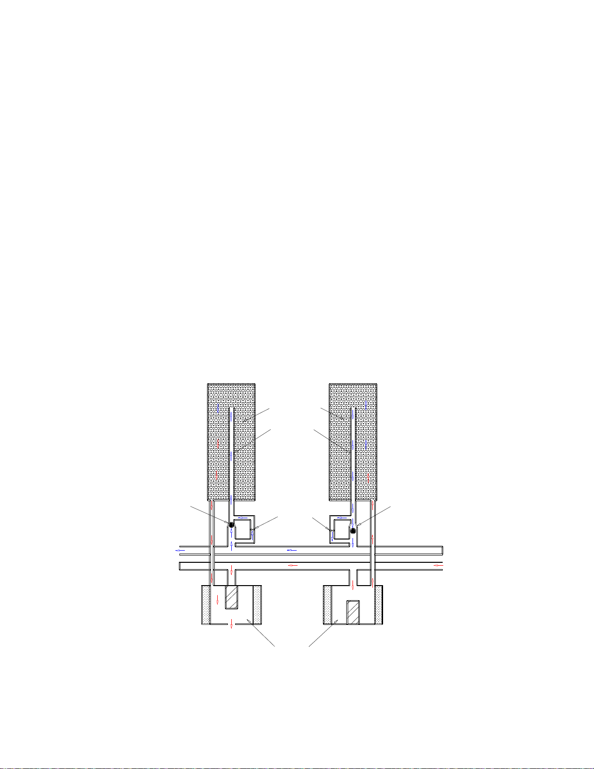
3.3 Heatless Dryer.........................................................................................................4
3.3.1 Tower #1....................................................................................................... 4
3.3.2 Tower #2....................................................................................................... 4
3.4 Humidity Sensing Tube..........................................................................................5
3.5 Capacity Control Valve..........................................................................................5
3.6 Pressure Switch and Storage Tank........................................................................5
3.7 Pressure Regulator and Shut-Off Valve ................................................................5
3.8 High/Low Pressure Switch.....................................................................................5
3.9 Alarm Summary.....................................................................................................5
3.9.1 High Pressure Alarm – HIGH PRESSURE..................................................... 5
3.9.2 Low Pressure Alarm – LOW PRESSURE ...................................................... 5
3.9.3 Air Compressor Maintenance Alarm - COMP. RUN TIME ALARM............. 5
3.9.4 Humidity Condition – HUMIDITY, -COND.-................................................ 6
3.9.5 Humidity Alarm – HUMIDITY ALARM....................................................... 6
3.10 Humidistat .............................................................................................................6
3.11 Desiccant................................................................................................................6
3.12 Logic Scan LED.....................................................................................................6
3.13 Alarm LED ............................................................................................................6
SECTION 4 – INSTALLATION AND START-UP........................................... 7
4.1 Inspection................................................................................................................7
4.2 Installation Procedure.............................................................................................7
4.3 Location ...................................................................................................................7
4.4 Electrical Hook-Up..................................................................................................7
4.5 Start-Up ...................................................................................................................8
SECTION 5 – TEST PROCEDURES................................................................. 9
5.1 Low Pressure Alarm Test........................................................................................9
5.2 High Pressure Alarm Test.......................................................................................9
5.3 Humidity Condition Test.........................................................................................9
5.4 Humidity Alarm Test ............................................................................................10
5.5 Compressor Performance Test.............................................................................. 11
SECTION 6 – MAINTENANCE .......................................................................12
6.1 Routine Maintenance ............................................................................................ 12
6.2 Maintenance Matrix..............................................................................................13
6.3 Recommended Spare Parts List............................................................................14
6.4 Air Compressor Safety Valves ..............................................................................15

ii
6.5 Air Compressor Pressure Switch..........................................................................15
6.6 High/Low Pressure Alarm Adjustment................................................................15
6.7 Capacity Control Valve Adjustment.....................................................................15
6.8 Air Compressor Maintenance Kit.........................................................................16
6.9 Air Compressor Troubleshooting Chart ..............................................................17
6.10 Air Compressor Disassembly..............................................................................18
6.11 Air Compressor Assembly...................................................................................18
6.12 Heatless Dryer (dehydrator) ...............................................................................19
6.13 Pressure Regulator ..............................................................................................19
6.14 Humidity Alarm...................................................................................................19
6.15 Maintenance Kit..................................................................................................21
6.16 Dehydrator Parts List..........................................................................................22
6.17 Compressor Parts List........................................................................................24
SECTION 7 – TROUBLESHOOTING INFORMATION GUIDE .................29
7.1 Alarm Display Summary......................................................................................30
7.2 Air System.............................................................................................................30
7.3 Humidity Alarm System.......................................................................................31
7.4 Electrical System ................................................................................................... 32
7.5 Dehydrator.............................................................................................................33

iii
FIGURES
AIR FLOW PATH............................................................................................... 3
PUREGAS HEATLESS DRYER........................................................................ 4
HUMIDITY BOARD........................................................................................... 8
HUMIDITY TIME DELAY SWITCH............................................................... 9
CONTROL BOARD P05847F ...........................................................................10
COMPRESSOR PERFORMANCE TIME DELAY SWITCH........................11
AIR COMPRESSOR PRESSURE SWITCH....................................................15
HIGH/LOW PRESSURE ALARM SWITCH ..................................................15
EXPLODED VIEW OF PUREGAS HEATLESS DRYER..............................23
EXPLODED VIEW OF COMPRESSOR AND MOTOR ASSEMBLY .........24
TOP PANEL FRONT VIEW.............................................................................26
TOP PANEL REAR VIEW................................................................................26
WIRING DIAGRAM..........................................................................................28
CHARTS
PUREGAS P4200DCO3A AIR DRYER CHARACTERISTICS...................... 2
PUREGAS P4200DCO3A MAINTENANCE....................................................13
AIR COMPRESSOR TROUBLESHOOTING.................................................17
DEHYDRATOR PARTS LIST..........................................................................22

1
SECTION 1 – GENERAL
1.1 Scope of Manual
This instruction Manual covers the description, operating principles, installation and start
up, test procedures, maintenance, and troubleshooting techniques for the Model
P4200DCO3A Air Dryer. The Model P4200DCO3A is designed for indoor use.
1.2 Initial Inspection
Carefully inspect both the exterior and interior of the air dryer for any shipping damage.
1.3 Warranty
Before starting the dryer, read the manual thoroughly to become acquainted with the
principles of operation. Follow installation, start-up, and test procedures in proper
sequence so as not to void the warranty.
IMPORTANT:
ANY SHIPPING DAMAGE MUST BE BROUGHT TO THE IMMEDIATE
ATTENTION OF THE CARRIER. THE MANUFATURER IS NOT
RESPONSIBLE FOR SHIPPING DAMAGE
CAUTION !!!
FAILURE TO FOLLOW PROPER SEQUENCE FOR INSTALLATION,
START-UP, AND TEST WILL VOID THE WARRANTY.

2
SECTION 2 – DESCRIPTION
The model P4200DCO3A Air Dryer employs the principles of compression and physical
adsorption. The operation is fully automatic and relatively maintenance free. The unit
essentially consists of an oilless air compressor and heatless desiccant dryer. It also
incorporates the necessary gauges, controls, and automatic alarms to ensure the delivery
of dry air at the proper pressure and relative humidity. The air dryer will automatically
shut down in the event of a high humidity alarm. Specific characteristics are shown
below in Chart 1.
Chart 1
PUREGAS P4200DCO3A AIR DRYER CHARACTERISTICS
SPECIFICATIONS
NORMAL OUTPUT CAPACITY: 2,600 SCFD
EMERGENCY OUTPUT CAPACITY: 4,200 SCFD
ALARMS AND INSTRUMENTATION: Standard alarms with remote
monitoring capability. Individual
alarm indication display
HEAT DISSAPATION: 4000 BTU/HR, Maximum
SIZE: 25 1/8” Wide x 21” Deep x 49” High
NET WEIGHT: 280 Lbs. (127 kg)
ELECTRICAL: 115 VAC, 1 Ph, 60 Hz
DEWPOINT: -40 oF
DEHYDRATOR: Solid State Timer/ D.C. Valves
DELIVERED AIR PRESSURE: Adjustable 0-20 PSIG
AIR COMPRESSOR: Two-cylinder, ¾ hp, oilless type
NOISE LEVEL WITH 56 dbA at 3’, 53 dbA at 10’
COMPRESSOR RUNNING: (under normal conditions, compressor will
only operate 50% of the time)
DRY AIR OUTLET CONNECTIONS: Low Pressure ½” NPT Female
High Pressure ½” NPT Female

3
SECTION 3 – PRINCIPLES OF OPERATION
This unit has successfully completed a three day operational test at the factory. Each
component was individually calibrated and tested over its full range of operation. The
operation and existing settings are explained in the sections following.
3.1 Air System
The air flow is shown schematically in the Figure 1 below.
3.2 Air Compressor
Ambient air is drawn through the intake filter on the air compressor and compressed to
approximately 50 PSIG. It then passes to the pre-cooler where hot compressed air is
cooled before entering the heatless dryer.
FIGURE 1
AIR FLOW PATH
precooler
dehydrator
capacity control valve
(48-52 PSIG)
tank
high pressure
outlet
low pressure
outlet
tank pressure gauge
pressure regulator
humidity sensing tube
flowmeter
low pressure gauge
pressure
switch
high/low pressure alarms
intake filters

4
3.3 Heatless Dryer
The Puregas heatless dryer, which is located downstream from the air compressor,
consists of two desiccant-filled towers, a manifold, a solid state timer and two solenoid
valves. It is arranged and cycled so one tower delivers dry air while the desiccant in the
other tower is purged and dried by a small quantity of dry air supplied by the first tower,
refer to Figure 2. The tower functions reverse at 30 second intervals. The operation of
the towers follows below.
3.3.1 Tower #1
Air from the compressor enters the solenoid valve., which is controlled by an
electrical timer and is forced upward through the desiccant tower. Moisture is
removed from the air as it passes over the desiccant. The dried air is the forced down
through the air tube in the center of the desiccant tower, out through an open ball
check valve and is finally delivered through the capacity control valve to the air
storage tank.
3.3.2 Tower #2
Simultaneously with the operation of Tower 1, as described above, the solenoid valve
of Tower 2 is opened to the atmosphere. The main dry air Supply from Tower 1 is
prevented from entering Tower 2 by automatic closure of the ball check valve.
However, a small quantity of the dry air is forced through an orifice into the air tube,
then down through the desiccant bed absorbing the moisture previously collected
while Tower 2 was furnishing dry air (as Tower 1 is doing at this time), and finally
expelled to the atmosphere through the solenoid valve. The desiccant in Tower 2 is
thus dried and made ready for the next cycle reversal. Tower1 and Tower 2 reverse
functions: Tower 2 takes over the air drying operation, while the desiccant in Tower 1
is being dried.
Figure 2
PUREGAS HEATLESS DRYER
dessicant
air tube
orifice
tower 1
tower 2
check
valve
(closed) check
valve
(open)
wet gas
inlet
dry gas
outlet
to
atmosphere 3-way
valve
solenoid

5
3.4 Humidity Sensing Tube
Air is then channeled to the humidity sensing tube and flows over the humidity sensor.
The humidity sensor (not shown) will signal the alarm systems if the relative humidity
rises above 10%. A relative humidity rise would indicate a malfunction.
3.5 Capacity Control Valve
This valve has two functions. First, it maintains the proper purge pressure through the
heatless dryer, which will insure dry air delivery under maximum flow condition. It also
acts as a check valve preventing air in the storage tank from bleeding back through the
heatless dryer when the air compressor is not running.
3.6 Pressure Switch and Storage Tank
Once the air passes through the capacity control valve, it is directed in to the air storage
tank. The on/off pressure switch then signals the compressor to shut down at 50 PSIG.
The Air compressor will remain off until the tank pressure drops below 20 PSIG. Then
the on/off pressure switch will start the compressor, and the cycle continues. For
adjustment refer to Section 6.5 and Figure 7.
3.7 Pressure Regulator and Shut-Off Valve
From the air storage tank, the air is channeled to the high pressure outlet valve and the
low pressure outlet which is regulated by the pressure regulator (0-20 PSIG).
3.8 High/Low Pressure Switch
Dry air will flow to the high/low pressure switch which signals an alarm if the pressure
drops below, or rises above the preset values. For adjustments of the pressure switch,
refer to Section 6.6, and Figure 8.
3.9 Alarm Summary
The alarms and conditions that can be displayed are described below.
3.9.1 High Pressure Alarm – HIGH PRESSURE
This alarm results when the outlet pressure, as read on the outlet pressure gauge,
exceeds the set point of the high pressure switch following a 30 second delay. The
switch can be adjusted. It is factory set to alarm when the outlet pressure exceeds 12
PSIG. Refer to Section 6.6 and Figure 8 for the adjustment procedure.
3.9.2 Low Pressure Alarm – LOW PRESSURE
This alarm results when the outlet pressure drops below the set point of the low
pressure switch. The switch can be adjusted. It is factory set to alarm when the
pressure drops below 6.5 PSIG following a 30 second delay. Refer to Section 6.6 and
Figure 8 for the adjustment procedure.
3.9.3 Air Compressor Maintenance Alarm - COMP. RUN TIME ALARM
This alarm occurs when the air compressor and heatless dryer run time exceeds the
set point of the solid state compressor performance time delay switch. The switch is
may be adjusted. It is factory set at approximately 2 minutes. Refer to Figure 5 for
adjustment location.

6
3.9.4 Humidity Condition – HUMIDITY, -COND.-
During the time when the HUMIDITY, -COND.- is being displayed the following
sequence occurs:
A. The solid state humidity time delay switch starts counting down from its preset
value, which is factory set at 2 minutes.
B. HUMIDITY, -COND.- is shown on the alarm display.
3.9.5 Humidity Alarm – HUMIDITY ALARM
This alarm will only be displayed after the HUMIDITY –COND.- time delay has
timed out. When HUMIDITY ALARM is displayed, the air compressor and
heatless dryer do not operate until the reset switch is toggled.
3.10 Humidistat
The humidity level is represented by the seven LED’s, three red and four green, located
just below the alarm display. When all LED’s are energized, the humidity level is below
2% relative humidity, indicating the system is operating correctly.
3.11 Desiccant
During shipment, the desiccant in the heatless dryer towers may have absorbed some
moisture. If this is the case, one or more LED’s may be off during initial start-up,
however they will come on as the desiccant dries out during operation. All LED’s on the
humidistat should be energized after 15 minutes of operation.
3.12 Logic Scan LED
The logic scan LED will pulse on and off whenever the dryer is turned on. This indicates
the display board is scanning for alarms.
3.13 Alarm LED
The alarm LED is normally off. It will only energize when an alarm condition is present
on the digital alarm display. The alarm LED will energize during the following
conditions: HUMIDITY ALARM,HIGH PRESSURE,LOW PRESSURE, and
COMP. RUN TIME ALARM. The alarm LED will not energize when HUMIDITY –
COND.-is displayed or when the digital alarm display is blank.
NOTE:
If the humidity condition does not clear, and the humidity time delay times
out, the air compressor/heatless dryer will shut down and HIGH,
HUMIDITY ALARM will appear on the alarm display. If the humidity
condition does clear, the alarm will no longer be displayed on the display,
and the timer will be reset to zero.

7
SECTION 4 – INSTALLATION AND START-UP
4.1 Inspection
Remove the lower front door and open the upper instrument panel. Carefully inspect
both the exterior and interior of the air dryer for any shipping damage.
4.2 Installation Procedure
Step 1. Close the upper instrument panel and install the lower panel before moving the
dryer to its permanent location.
Step 2. Remove the shipping blocks from beneath the compressor plate. This permits the
compressor assembly to float freely on the rubber vibration pads.
4.3 Location
The unit should be installed in an environment that is free from abrasive dust and
chemicals. The optimum temperature range is between 40oand 85 oF. Although the unit
will operate at temperatures up to 120 oF, the operating life of the components decreases
dramatically at temperatures above 85 oF.
4.4 Electrical Hook-Up
The air dryer operates on 115 VAC, I phase, 60 hertz power.
Before plugging in the air dryer into the electrical outlet, make sure the main power
switch is in the OFF position.
CAUTION !!!
It is extremely important to perform the installation, start-up, and test
procedures in Sections 4 and 5 in the sequence outlined or damage to
components may result and the warranty voided.
IMPORTANT:
ANY SHIPPING DAMAGE MUS TBE BROUGHT TO THE IMMEDIATE
ATTENTION OF THE CARRIER. THE MANUFATURER IS NOT
RESPONSIBLE FOR SHIPPING DAMAGE
NOTE:
Failure to remove shipping blocks may damage the mounting assembly.
IMPORTANT:
A 15 amp minimum service must be provided. The incoming power
to the dryer should have 20 amp SLO-BLO fuses. A minimum of 14 AWG
wire must be used to connect the dryer.

8
4.5 Start-Up
A plastic plug with a small hole is located in the low pressure outlet port at the rear of the
dryer. This orifice plug will permit the unit to operate in a simulated “on-line” condition.
A. Place the main power switch to the ON position.
B. The logic scan LED will start flashing.
C. The air compressor, heatless dryer and ventilating fan will start running and the air
will flow through the low pressure orifice plug.
D. LOW PRESSURE will appear on the alarm display until the outlet pressure gauge
reads approximately 6 PSIG or more. During the time that LOW PRESSURE
appears on the display, the alarm LED will also be energized.
E. HUMIDITY –COND.- may appear on the alarm display. If HUMIDITY –COND.-
does not clear within approximately two minutes, HUMIDITY ALARM will appear
on the alarm display and the air dryer will shut down. If this happens, simply toggle
the reset switch. This will allow the unit to run for approximately two more minutes.
The HUMIDITY –COND.- should clear within 10-15 minutes.
F. The seven humidity level LED’s will energize when the desiccant in the heatless
dryer is dry. If, however, during initial start-up, HUMIDITY –COND.- appears in
the alarm display, two more LED’s will be off. The LED’s will energize as the
desiccant dries out. This should take less than 15 minutes. It may be necessary to
increase outlet flow to 2160 SCFD during this “dry out” period.
G. The outlet pressure gauge will stabilize at approximately 10 PSIG.
H. The air pressure in the air storage tank will cycle between 20 and 50 PSIG. This may
be seen on the tank pressure gauge.
I. The alarm LED will be energized only when the HUMIDITY ALARM,HIGH
PRESSURE,LOW PRESSURE, and COMP. RUN TIME ALARM appear on the
alarm display. The alarm LED will be off in all other cases.
J. Check for pressure leaks that may have occurred during shipment with soapy water.
Be careful not to spray water on any circuit boards within the unit.
Figure 3
HUMIDITY BOARD
humidity board
test switch open circuit
alarm
alarm (off)
P-07580F

9
SECTION 5 – TEST PROCEDURES
5.1 Low Pressure Alarm Test
A. Open the front instrument panel.
B. Locate the outlet pressure regulator and loosen the locking nut so that the regulator
can be adjusted.
C. Rotate the knob counterclockwise and reduce the pressure on the outlet pressure
gauge to approximately 5 PSIG.
D. At this point, LOW PRESSURE will appear on the alarm display. Turn the knob
clockwise and increase the pressure on the outlet pressure gauge to 10 PSIG. LOW
PRESSURE will disappear from the alarm display. The low pressure alarm set point
is factory set at 6 PSIG.
5.2 High Pressure Alarm Test
A. Rotate the pressure regulator knob clockwise until the outlet pressure gauge reads
approximately 15 PSIG. HIGH PRESSURE will appear on the alarm display.
B. Rotate the knob counterclockwise until the outlet pressure gauge reads approximately
10 PSIG. Toggle the reset switch and HIGH PRESSURE will disappear. The
alarm set point is factory set at 12.5 PSIG.
5.3 Humidity Condition Test
Locate SW2 on the P05847F control board. Select the desired time delay by setting only
one of the four dip switches. Select switch one on for one minute, two on for two
minutes, and so fourth. If all four switches are off, a 5 minute delay is set. If longer
delays are required, turn SW4 on, this multiplies all delays by 2. Refer to Figure 4
below.
Figure 4
HUMIDITY TIME DELAY SWITCH
WARNING !!!
Avoid contact with energized circuits when access doors are open.
REMOVE ALL JEWELRY before performing any test or
maintenance on the air dryer.
NOTE:
Only one switch should be in the ON position at any one time.
Figure 4 below shows the #2 switch in the ON position
1 2 3 4
ON
delay switch
SW4
humidity time

10
5.4 Humidity Alarm Test
A humidity alarm will result after the system has remained in a humidity condition for
longer than the time set on the humidity time delay switch. To perform the test, simply
keep the dryer in a humidity condition for longer than two minutes. This may be done by
depressing the humidity test switch on the humidity board. After the dryer has been in a
humidity condition for longer than two minutes, the following should occur:
A. HUMIDITY ALARM will appear on the alarm display.
B. The alarm LED will be on while the HUMIDITY ALARM appears on the
display.
C. The air compressor will shut down. compressor on (LD2) should de-energize
on the P05847F logic board.
D. The two green humidity LED’s, possibly some or all of the red LED’s, will
de-energize on the humidity display.
Toggle the reset switch on the front panel, and the dryer will start-up again. The LED’s
will energize and the alarm will no longer be displayed.
Figure 5
CONTROL BOARD P05847F
display
to
board
L1
by-pass
open on alarm
common
close on alarm
close on alarm
close on alarm
P-05847F
SSR
P08033G
cylce kit
interface
110 VAC
power in
L1L2
high pressure switch
low pressure switch
tank pressure switch
on
off
1 2 3 4 1 2 3 4
1
2
3
4
5
6
7
8
9
10
11
12
1
2
3
4
5
6
7
8
9
10
11
1111
111 1 2222
2 2
2
1
44
by-pass
solenoid
on
compressor
on
latch
humidity
C.P.
hi flow hi pres lo pres
scan
compressor perf humidity
delay x 2

11
5.5 Compressor Performance Test
A compressor performance alarm (COMP. RUN TIME ALARM) will result when the
air compressor remains running for a period longer than normal for a particular
application.
Example: If the time between the air compressor starting and stopping is one minute,
then the normal run time is one minute.
With the normal cycle at one minute, the compressor performance time delay switches,
located on the P05847F control board, should be set with the two minute switch ON and
all of the other switches OFF. SW4 should be at X1. See Figure 6 below. A compressor
performance alarm will appear on the alarm display if, for any reason, the air compressor
runs continuously for the set period of time.
The following items represent some possible reasons a COMP. RUN TIME ALARM
would be displayed. Refer to the troubleshooting guide for further details in Section 7.2.
A. An increase in flow to the cables.
B. A leak in the internal pneumatic connections in the air dryer.
C. A “weak” air compressor. (the air compressor needs maintenance)
D. A faulty solenoid valve in the heatless dryer.
To test the alarm, simply create a temporary leak in the dryer which will force the air
compressor to run longer than two minutes. COMP. RUN TIME ALARM will appear
on the display. Remove the leak from the dryer, toggle the reset switch, and the alarm
should clear from the display.
Figure 6
COMPRESSOR PERFORMANCE TIME DELAY SWITCH
NOTE:
The compressor performance time delay is factory set at two minutes.
CAUTION !!!
It is extremely important to perform the installation, start-up, and test
procedures in Sections 4 and 5 in the sequence outlined or damage to
components may result and the warranty voided.
1 2 3 4
ON
SW4
compressor performance
time delay switch

12
SECTION 6 – MAINTENANCE
6.1 Routine Maintenance
The following maintenance procedure is recommended by Puregas. If maintenance
problems persist after thoroughly consulting this manual, contact Puregas Service
Department, 1-800-521-5351 extension 2156.
SIX MONTH CHECK
üRun times (ON and OFF)
üFlow rate (compare to previous flow rate)
üHumidity alarm
üSafety valve
üPressure switch (ON at 20 PSIG, OFF at 50 PSIG)
üHigh/Low pressure alarm (HIGH at 12 PSIG, LOW at 6 PSIG)
üCapacity control valve (set at 48-52 PSIG)
üReplace the air compressor intake filter felts, P3986
üReplace cabinet filter element, P05893
üClean the air pre-cooler
ONE YEAR (or 4,000 hours) CHECK
üChange the items in the compressor maintenance, refer to Section 6.15
üChange the humidity sensing element
üCheck all wire connections
üRepeat six month check. NOTE: order maintenance kit, P07511
TWO YEAR (or 8,000 hours) CHECK
üChange the items in the heatless dryer maintenance kit, P200499S
üRepeat six month check
üRepeat one year check
CAUTION !!!
When working around energized circuits, extreme caution should be taken to
prevent injury to personnel and damage to equipment.
IMPORTANT !!!
It is very important that routine maintenance be performed at six month, one
year (or 4,000 hours), and two year (or 8,000 hours) intervals to keep dryer
operating efficiently. Puregas recommends a historical
record be maintained on all air dryers.
NOTE:
After performing maintenance on air dryers, always soap test pressure fittings to
insure there are no leaks. Wiring should be checked on a routine basis, whether
maintenance has been performed or not.

13
6.2 Maintenance Matrix
Maintenance
Procedure Frequency
Interval Time
Required
Flowrate
Check
6 months
1
Humidity Alarm
Check
6 months
5
High/Low pressure alarm Check 6 months 5
Compressor pressure
switch
Check 6 months 5
Safety valve
Check
6 months
5
Outlet regulator Check/Adjust 6 months 5
Ventilation filter
Replace
6 months
5
Compressor intake filter Replace 6 months 5
Compressor performance Check 6 months 5
Capacity control valve Check 6 months 5
Precooler coils
Clean
6 months
10
Air fittings
Leak test
6 months
15
Heatless dryer kit Replace 2 years 60
Humidity and compressor
performance delay Check 6 months 10
Air compressor kit Replace 1 year 60
Humidity sensing element Replace 1 year 5
Chart 2
Puregas P4200DCO3A Maintenance
The air compressor kit, and the humidity sensing element are supplied in the annual
maintenance kit. The part number for the heatless dryer maintenance kit is P200499S.

14
6.3 Recommended Spare Parts List
Part Number Description QTY
P02626S vibration mounts 4
P010369 pressure switch 1
P05285 precooler fan 1
P07580F2 humidity board 1
P5000647D humidity sensor 2
P05847F1 logic board 1
P07599F1 display board 1
P05992 solid state relay (25 amp) 1
P06136 circuit breaker (15 amp) 1
P400589DC1 solenoid valve assembly 2
P200499S heatless dryer maintenance kit 1
P06521F1 cycle timer 1
P07511 compressor maintenance kit 1
P4634 capacity control valve 1
OPTIONAL SPARE PARTS:
P39663LS ¾ HP Air compressor
Quantities listed are recommended spare parts per five air dryers.
Table of contents
Other Puregas Dehumidifier manuals

Puregas
Puregas MHT Series User manual

Puregas
Puregas P10KW User manual

Puregas
Puregas P1500W Series User manual

Puregas
Puregas P550W Series User manual

Puregas
Puregas P10KW User manual

Puregas
Puregas P1500W Series User manual

Puregas
Puregas P4200PM User manual

Puregas
Puregas P550W2 Series User manual

Puregas
Puregas P20KW User manual

Puregas
Puregas MDH Series User manual