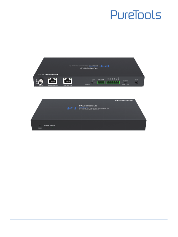
PureTools PT-IP-CNTRL10 User manual

UserManual
PT-IP-CNTRL10
User Manual
AV over IP Network Interface for PT-IP-HD-26x Series
Model PT- IP-CNTRL10
Designedin Germany
© 2022PureLink GmbH All rights reserved.
V1.0

UserManual
PT-IP-CNTRL10
Preface
Read this user manual carefully before using this product. Pictures shown in this
manual are for reference only. Different model layouts andspecifications are subject
to the physical product.
This manual is for operation instructions only, not for any maintenance usage.
In the constant effort to improve our product, we reserve the right to make changes in
functions or parameters without prior notice or obligation.
Trademarks
Product model and logo are trademarks. Any other trademarks mentioned in this
manual are acknowledged as the properties of the trademark owner. No part of this
publication may be copied or reproduced without the prior writ ten consent.
FCC Statement
This equipment generates, uses and can radiate radio frequency energy and, if not
installed and used in accordance with the instructions, may cause harmful
interference to radio communications. It has been tested and found to comply with
the limits for a Class B digital device, pursuant to part 15 of the FCC Rules. These
limits are designed to provide reasonable protection against harmful interference in
a commercial installation.
Operation of this equipment in a residential areais likely to cause interference, in
which case the user at their own expense will be required to take whatever measures
may be necessary to correct the interference.
Any changes or modifications not expressly approved by the manufacture wouldvoid
the user’s authority to operate the equipment.

UserManual
PT-IP-CNTRL10
REACH | 1907/2006/EU
ROHS | 2011/65/EU
PureLink hereby declares that this product PureTools PT-IP-CNTRL10 complies with
Directives 1907/2006/EU und 2011/65/EU.
EMC / LVD (Electro Magnetic Compatibility / Low Voltage Directive)
PureLinkGmbHherebydeclares thatthis product PureTools PT- IP-CNTRL10
complies with Directives 2014/30/EU and 2014/35/EU. The full text of the EU
Declaration of Conformity is available at the following Internet address:
http://www.purelink.de/ce/4251364736197_CE.pdf

UserManual
PT-IP-CNTRL10
SAFETY PRECAUTIONS
To ensure the best from the product, please read all instructionscarefully before
using the device. Save this manual for further reference.
Unpack the equipment carefully and save the original box and packing material
for possible future shipment
Follow basic safety precautions to reduce the risk of fire,electrical shock and
injury to persons.
Do not dismantle the housing or modify the module. It may result in electrical
shock or burn.
Using supplies or parts not meeting the products’ specifications may cause
damage, deterioration or malfunction.
Refer all servicing to qualified service personnel.
To prevent fire or shock hazard, do not expose the unit to rain, moisture or install
this product near water.
Do not put any heavy items on the extension cable in case of extrusion.
Do not remove the housing of the device as opening or removing housing may
expose you to dangerous voltage or other hazards.
Install the device in a place with fine ventilation to avoid damage caused by
overheat.
Keep the module away from liquids.
Spillage into the housing may result infire, electrical shock, or equipment damage.
If an object or liquid falls or spills on to the housing, unplug the module
immediately.
Do not twist or pull by force ends of the optical cable. It can cause malfunction.
Do not use liquid or aerosol cleanersto clean this unit. Always unplug the power
to the device before cleaning.
Unplug the power cord when left unused for a long period of time.
Information on disposal for scrapped devices: do not burn or mix with general
household waste, please treat them asnormal electrical wastes.

UserManual
PT-IP-CNTRL10
Content
1. Product Introduction...........................................................................................................
1.1 Introduction....................................................................................................................
1.2 Features............................................................................................................................
1.3 Package List.....................................................................................................................
2. Panel Description.................................................................................................................
2.1 Encoder Panel.................................................................................................................
2.2 Decoder Panel................................................................................................................
2.3 IR Pin Definition.............................................................................................................
3. Specification..........................................................................................................................
4. System Diagram...................................................................................................................
5. Rack Mounting Instruction................................................................................................
5.1 6U Rack Mounting.........................................................................................................
5.2 1U Rack Mounting.........................................................................................................
6. Web GUI User Guide............................................................................................................
6.1 Preparation before Entering the System..................................................................
6.2 Functions and Operation.............................................................................................
7. After-Sales Service...............................................................................................................
Asking for Assistance...............................................................................................................
2
2
2
3
3
3
4
5
5
6
7
7
9
10
10
14
27
29
1

1.1 Introduction
1.2 Features
This Video over IP Controller is used to control and manage H.264/H.265 IP products.
It supports dual 100M network ports, which can realize dual�network isolation of
Control network and Multicast video distribution network. Built-in Web GUI, TCP and
RS-232 control are supported. It supports POE function and wide-band 12V IR signal
receiving. Since the demand of IP products is daily increased in the current market,
the IP Controller will be widely applied in more and more different scenarios.
UserManual
PT-IP-CNTRL10
2
1. Product Introduction
•Easy to create project, control and manage the system
•SSH security compatible
•Built-in Web GUI control interface, supporting Drag & Drop operations
•Supports image preview
•Supports video, audio, RS-232, IR, KVM control and management of the
distributed system
•Dual network ports (VIDEO LAN port supports POE function) to isolate
Controls and Multicast networks.
•Supports LAN/RS-232 port control and third-party central control
•Supports IR signal receiving (3.5mm audio jack, 12V level)
•4 channel GPIO control ports (5V/12V optional level)
•Multiple circuits protection, lightning protection and ESD design
•Reliable system design, ensuring 7*24 hours reliable and stable work

1.3 Package List
•1 x Video over IP Controller
•1 x 20kHz-60kHz 12V IR Receiver Cable (1.5 meters)
•1 x 3-pin 3.81mm Phoenix Connector (Male)
•1 x 6-pin 3.81mm Phoenix Connector (Male)
•2 x Mounting Ears
•4 x Machine Screws (KM3*6)
•1 x 12V/1A Locking Power Adapter
•1 x User Manual
UserManual
PT-IP-CNTRL10
3
2. Panel Description
2.1 Front Panel
RESET
POWER STATUS
123
1
2 POWER LED The red LED will light on when the Controller is powered on.
RESET Button Press and hold this button (about 10 seconds) until Status
LED starts flashing, Controller will be reset automatically.
3 STATUS LED
The status LED will flash in yellowish-green every 1 second
until Controller boots up completely and Control LAN is
ready, then it becomes solid.
No. Name Description

No. Name Description
1DC 12V DC 12V/1A power input port.
2VIDEO LAN
(POE)
3CONTROL
LAN The TCP/IP control network port.
100M Video LAN port, supporting POE function.
Note: When POE is enabled, DC 12V/1A power supply is
not required.
UserManual
PT-IP-CNTRL10
4
7IO LEVEL
DIP Switch
8 IR IN 12V IR signal input port.
6-pin Phoenix
Connector
4 channel I/O level outputs, 1 channel grounding,
1 channel power supply to the outside.
6
4MCU/Normal
DIP Switch
53-pin Phoenix
Connector RS-232 serial communication port.
Normal mode (Default): The RS-232 port is used for serial
port commands control.
MCU mode: The RS-232 port is used for MCU software
upgrade.
Used to control I/O level output and VOUT voltage.
Switch to left: 5V I/O level output, VOUT is 5V.
Switch to right: 12V I/O level output, VOUT is 12V.
2.2 Decoder Panel
87651 2 43
DC 12V
IO1
IO2
IO3
IO4
5V 12V
IR IN
IO LEVEL
VOUT
NORMAL
MCU

UserManual
PT-IP-CNTRL10
5
2.3 IR Pin Definition
IR RECEIVER
Power 12V
IR RECEIVER IR Signal
Grounding
3. Specification
Network Bandwidth 100M
Transmission
Distance
Technical
Metal Enclosure
Dimensions
Housing
2 x 100M LAN [RJ45 connector] [VIDEO LAN support POE]
1 x IR IN [3.5mm audio jack, 12V level]
1 x DIGITAL I/O [6-pin 3.81mm phoenix connector]
1 x RS-232 [3-pin 3.81mm phoenix connector]
204mm(W)×98mm(D)×21mm(H)
Control Ports
12V/1A
4.5W
0°C ~ 40°C / 32°F ~ 104°F
-20°C ~ 60°C / -4°F ~ 140°F
Power Supply
Operating
Temperature
Storage Temperature
Relative Humidity 20~90% RH (non-condensing)
Power Consumption
100m CAT 5E/6/6A/7
Black
Color
Weight 509g

UserManual
PT-IP-CNTRL10
6
4. System Diagram
Usage Precaution
• Make sure all components and accessories included before installation.
• System should be installed in a clean environment with proper temperature and
humidity.
• All of the power switches, plugs, sockets, and power cords should be insulated
and safe.
• All devices should be connected before power on.
The following diagrams illustrate typical input and output connections that can be
utilized with this product:
Video Wall
4 × DEC
Controller Box
1G Ethernet Switch
DVD TV
ENC DEC
DEC
DEC
DEC
TV
TV
TV
ENC
ENC
ENC
DC 12V
IO1
IO2
IO3
IO4
5V 12V
IR IN
IO LEVEL
VOUT
NORMAL
MCU
DC12V HDMIOUTHDMIIN
RLRL
AUDIOIN OUT
RXTX
RS-232 IRIN IROUT
DC12V HDMIOUT
RL RXTX
RS-232 IRIN IROUT
AUDIOOUT
DC12V HDMIOUT
RL RXTX
RS-232 IRIN IROUT
AUDIOOUT
DVD
DC12V HDMIOUTHDMIIN
RLRL
AUDIOIN OUT
RXTX
RS-232 IRIN IROUT
DVD
DC12V HDMIOUTHDMIIN
RLRL
AUDIOIN OUT
RXTX
RS-232 IRIN IROUT
DVD
DC12V HDMIOUTHDMIIN
RLRL
AUDIOIN OUT
RXTX
RS-232 IRIN IROUT
DC12V HDMIOUT
RL RXTX
RS-232 IRIN IROUT
AUDIOOUT
DC12V HDMIOUT
RL RXTX
RS-232 IRIN IROUT
AUDIOOUT
DC12V HDMIOUT
RL RXTX
RS-232 IRIN IROUT
AUDIOOUT
DC12V HDMIOUT
RL RXTX
RS-232 IRIN IROUT
AUDIOOUT
PC
TP-LINK
Router (optional)

UserManual
PT-IP-CNTRL10
7
Notes:
(1) For the default IP mode of Control LAN port of the Controller Box is DHCP, the PC also
needs to be set to “Obtain an IP address automatically” mode, and an optional DHCP
server (e.g. network router) is recommended in the system.
(2) If there is no DHCP server in the system, 192.168.0.225 will be used as the IP address
of Control LAN port. You need to set the IP address of the PC to be in the same network
segment. For example, set PC’s IP address as 192.168.0.88.
(3) You can access the Web GUI by inputting URL "http://controller.local" or the Control
LAN port IP address 192.168.0.225 (in case of no optional Router) on your computer's
browser.
(4) No need to care about settings of Video LAN port of the Controller Box, as they are
managed by Controller automatically (Default).
(5) When the Network Switch does not support POE, the Encoder, Decoder and Controller
Box should be powered by DC power adpter.
5. Rack Mounting Instruction
This product can be mounted in a standard 6U rack (Please contact your supplier for
6U rack sale). The mounting steps are as follows:
5.1 6U Rack Mounting
Step 1: Use included screws to fix two mounting ears on the product, as shown in the
figure below:

UserManual
PT-IP-CNTRL10
8
Step 2: Insert the product with mounting ears into a 6U rack (up to 10 units can be
installed vertically), as shown in the figure below:
Step 3: Use screws to fix mounting ears on the rack to complete the mounting, as
shown in the figure below:

UserManual
PT-IP-CNTRL10
9
5.2 1U Rack Mounting
This product also can be mounted in a standard 1U rack (up to 4 units can be installed
horizontally). The mounting steps are as follows:
Step 1: Stack two products on top of each other, then use included screws to fix two
1U rack panels on the products, as shown in the figure below:
Step 2: Fix two 1U rack panels on another two stacked products in the same way, then
use screws to fix two 1U rack panels together, as shown in the figure below:
Step 3: Fasten screws between two 1U rack panels, so that four products are mounted
in a 1U rack, as shown in the figure below:

UserManual
PT-IP-CNTRL10
10
6. Web GUI User Guide
You can use the built-in Web GUI to control all IP products at the Switch.
The operation method is shown as below.
Select the initial username (admin) and input the initial password (1234) on the above
login interface. Then, click “Login” to enter the Web GUI interface.
For the first time, you need to setup the project, as shown in the following figure:
Step 1: Input the Controller’s default IP address (192.168.0.225) or the URL (http://
controller.local) into the Web browser address bar on the PC to enter the Web GUI
login interface.
6.1 Preparation before Entering the System
Step 2: Click the “Close” button to load an existing project in web page directly, or
click “Next” button to go to the next step.

UserManual
PT-IP-CNTRL10
11
Step 3: Select “Automatically managed by Controller Box” as the IP mode of Video
LAN. (The other two modes are reserved items and are not currently available.) Then,
please connect all the devices according to the following diagram.
Video Wall
4 × DEC
Controller Box
1G Ethernet Switch
DVD TV
ENC DEC
DEC
DEC
DEC
TV
TV
TV
ENC
ENC
ENC
DC 12V
IO1
IO2
IO3
IO4
5V 12V
IR IN
IO LEVEL
VOUT
NORMAL
MCU
DC12V HDMIOUTHDMIIN
RLRL
AUDIOIN OUT
RXTX
RS-232 IRIN IROUT
DC12V HDMIOUT
RL RXTX
RS-232 IRIN IROUT
AUDIOOUT
DC12V HDMIOUT
RL RXTX
RS-232 IRIN IROUT
AUDIOOUT
DVD
DC12V HDMI OUTHDMIIN
RLRL
AUDIOIN OUT
RXTX
RS-232 IRIN IROUT
DVD
DC12V HDMI OUTHDMIIN
RLRL
AUDIOIN OUT
RXTX
RS-232 IRIN IROUT
DVD
DC12V HDMI OUTHDMIIN
RLRL
AUDIOIN OUT
RXTX
RS-232 IRIN IROUT
DC12V HDMIOUT
RL RXTX
RS-232 IRIN IROUT
AUDIOOUT
DC12V HDMIOUT
RL RXTX
RS-232 IRIN IROUT
AUDIOOUT
DC12V HDMIOUT
RL RXTX
RS-232 IRIN IROUT
AUDIOOUT
DC12V HDMIOUT
RL RXTX
RS-232 IRIN IROUT
AUDIOOUT
PC
TP-LINK
Router (optional)

UserManual
PT-IP-CNTRL10
12
Step 4: Click the “Next” button and wait for the completion to enter the interface as
shown in the figure below.
▪ If you select “Automatically add Encoders and Decoders to project”, and click the
“Scan” button to enter the Project page. All the connected devices will be listed in the
Current Devices list.
Then click “Start Scan & Auto Assign” to stop search.
▪ If you select “List all discovered Encoders and Decoders”, and click the “Scan” button
to enter the Project page. All the connected devices will be listed in the Unassigned
Devices list.

UserManual
PT-IP-CNTRL10
13
After scanning is complete, the “Assign” buttons behind Unassigned Encoders and
Unassigned Decoders in the figure below will become operable.
At this time, you can click the “Assign” button behind each unregistered Encoder or
Decoder to add the device to the project one by one.
Encoders and Decoders that have been added to the project will appear in the Current
Devices list, as shown in the figure below.

6.2 Functions and Operation
On this page, you can preview the Encoder/Decoder by clicking the drop�down list on
the right side.
UserManual
PT-IP-CNTRL10
14
■
Preview Page
■
Matrix Control Page
①
Encoders:
Display all the current Encoders. The text in the figure is the name of
the device.
②
Decoders:
Display all the current Decoders. The text on the first line is the name
of the Decoder, and the text on the second line refers to the Encoder where the
signal resource is from.

Operating Instructions:
(1) If an Encoder shows “No Signal”, it means that the Encoder cannot be dragged.
(2) If there is an image on an Encoder, it means that the Encoder can be dragged. As
shown in the figure above, if an Encoder is dragged to the place where the red
arrow points to, all Decoders will share the same signal resource from this Encoder;
if an Encoder is dragged to the place where the blue arrow points to, only the
indicated Decoder can receive signals from this Encoder.
UserManual
PT-IP-CNTRL10
15
■
Project Page
Operating Instructions:
(1) Click “Display ID” to display the ID number of the Decoders.
(2) Click “IP Address” to switch to the corresponding device Web page.
(3) Click “Save Project” to save the project file (config_file.json), so that you can use
the saved project next time without scanning devices again.
(4) Click “Load Project” to load the existing project in web page directly.
(5) Click “Clear Project” to clear the current project, then you will need to setup
devices again.
(6) Click “Start Scan & Auto Assign” to search devices that do not appear in the
current project; Click again to stop searching.
①
Current Devices:
Devices that have been added to the current project.
②
Unassigned Devices:
Devices not added to the current project.

UserManual
PT-IP-CNTRL10
16
(7) Click “Assign New Devices” to search new devices automatically and add to the
current project.
Operating Instructions:
(1) Click “Refresh” to refresh the data of the current Encoders.
(2) Click the drop-down list of EDID to set the current Encoder’s EDID.
(3) Click the drop-down list of Audio Selection to set the current Encoder’s
audio output.
(4) Click the icon on the left of ID to check the detail information about the
current Encoder, as shown in below:
■
Encoders Page
①
ID:
The ID of the current device. (Note: ID is not duplicated.)
②
Name:
The name of the current device. (Note: Name is not duplicated.)
③
MAC Address:
The MAC Address of the current device.
④
IP Address:
The IP Address of the current device. Clicking “IP Address” can switch
to the corresponding device Web page.
⑤
Firmware:
The Firmware version No. of the current device.
⑥
Status:
The status (online or offline) of the current device.
⑦
EDID:
The EDID of the current device.
⑧
Audio Selection:
The Audio Selection of the current device.
Table of contents