EN
- 9-
SPECIFICATI NS
SM-3512U SM-3520U
CHARACTERISTICS Professional 12-channel mixer with 2
outputs with independent volume
controls.
Professional 20-channel mixer with 2
outputs with independent volume
controls.
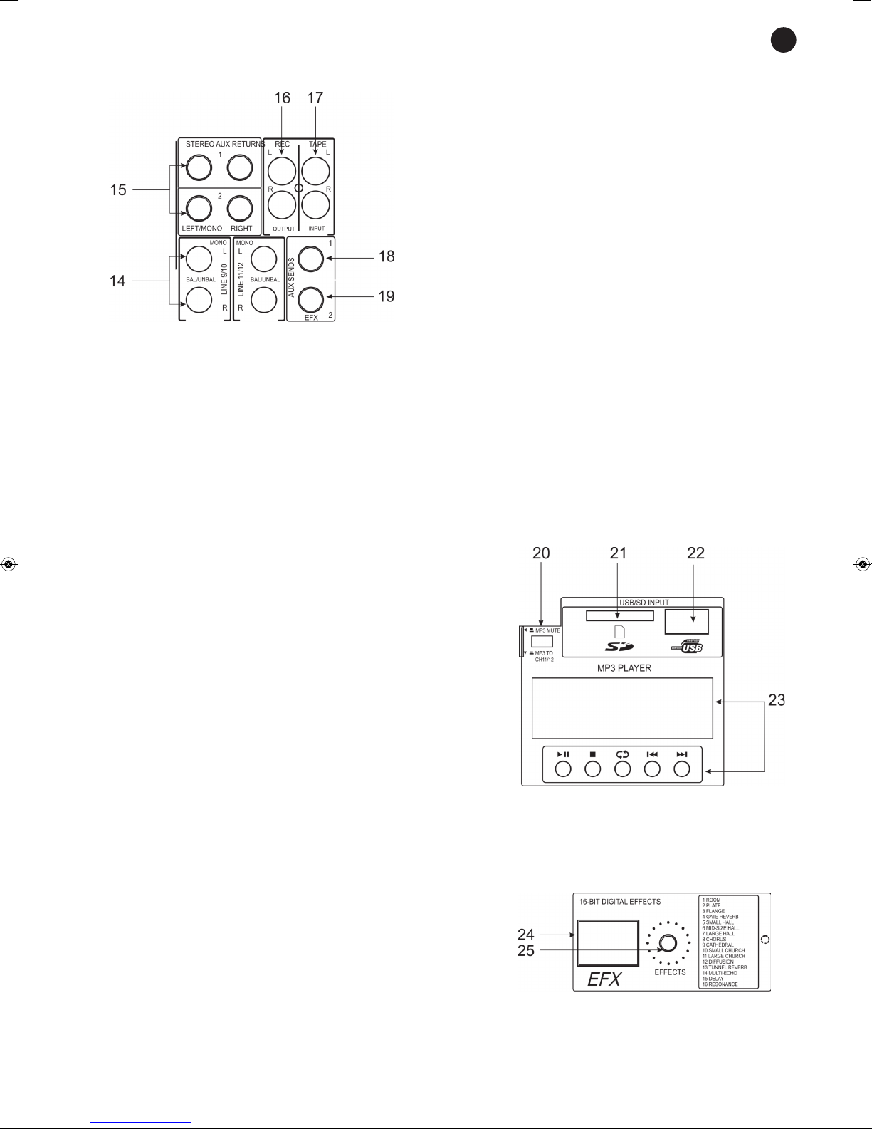
USB/SD/MP3 player.
16 digital effects processor.
USB PLAYER MP3 file player
USB port for USB memory connection
SD/MMC card reader
Accepts memories up to 8 GB
ID3 tag
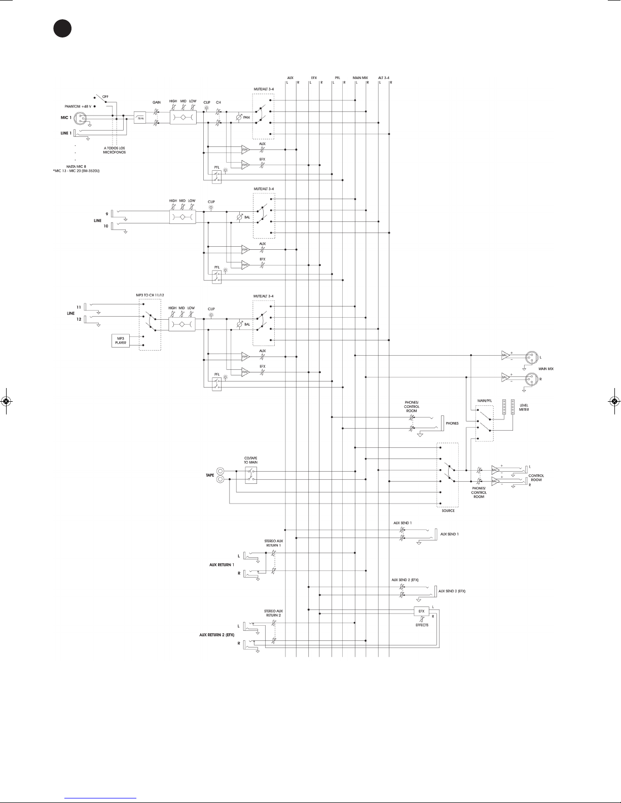
INPUTS 8 balanced XLR mics., 150 Ω
1.5 mV or 8 balanced lines, 6.3 mm
stereo jack, 20 000 Ω 150 mV
16 balanced XLR mics., 150 Ω
1.5 mV or 16 balanced lines, 6.3 mm
stereo jack, 20 000 Ω 150 mV
4 unbalanced lines, 2 x RCA, 20 000 Ω 150 mV
2 balanced auxiliary returns, 6.3 mm stereo jack, 20 000 Ω 1 V
1 tape input, 2 x RCA, 20 000 Ω 150 mV
2 lines, 2 x RCA, 20 000 Ω 150 mV
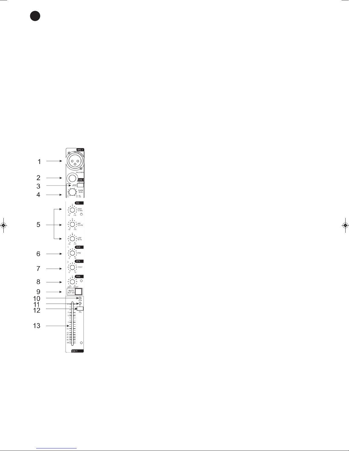
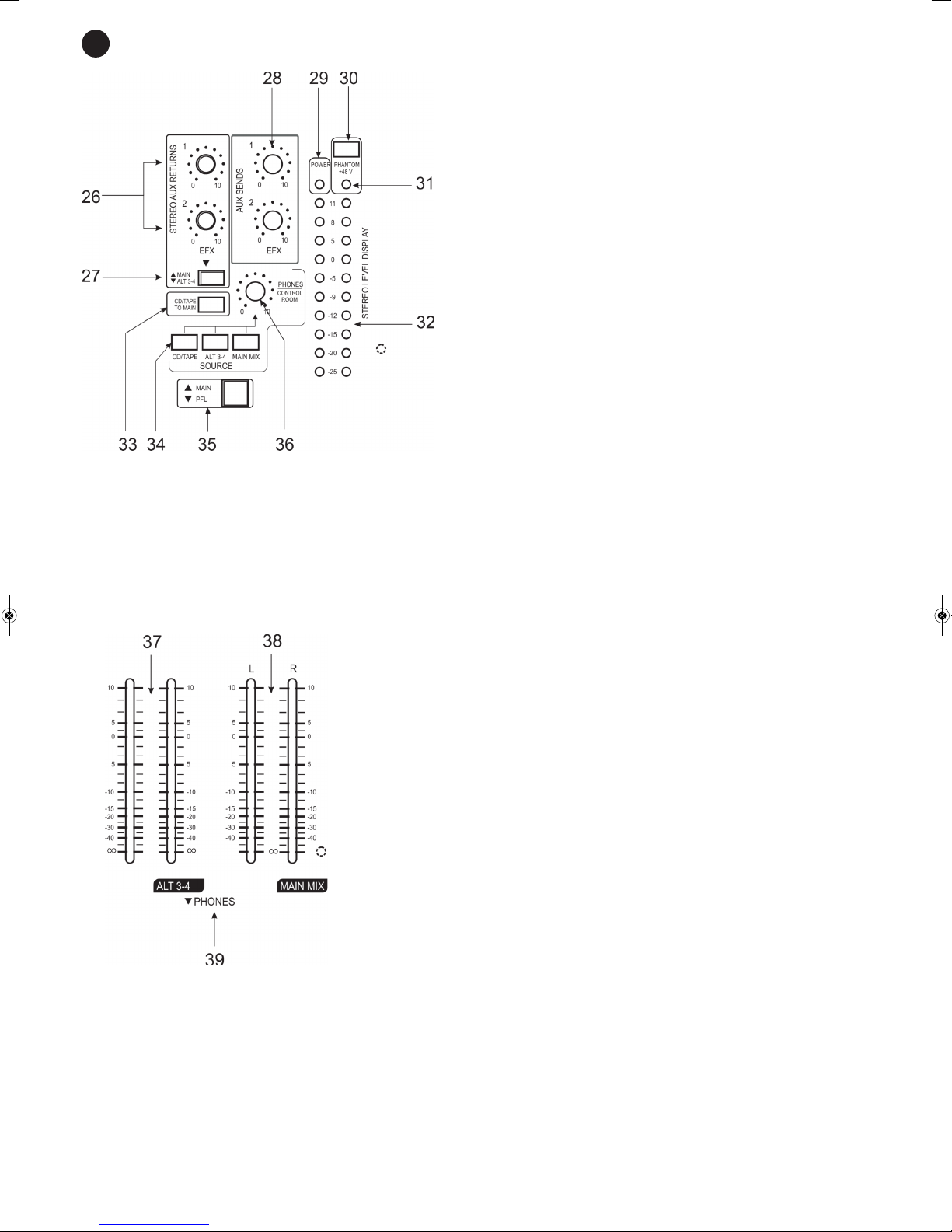
C NTR LS Mic./line: bass suppressor filter (18 dB, 75 z), gain, trebles (±15 dB, 80 z), mid
(±15 dB, 2500 z), bass (±15 dB, 12 000 z), auxiliary send, EFX send, pan,
mute-alt 3-4, PFL and sliding volume
USB/SD player: play/pause, stop, repeat, fast forward and rewind, and channel
11/12 (SM-3512U) or 19/20 (SM-3520U) allocation
Main mix: Sliding volume and output level LED indicator
Control room: Source and volume selection
Alt 3-4: Main/PFL source selection and volume
CD/tape: Allocation to the Main Mix output and the Control Room output
Auxiliary send: Volume control
Auxiliary returns: Volume control and allocation to Main/Alt 3-4
Effects processor: Effect selection
FUNCTI NS Cue through PFL headphones, assignable for each channel
Sliding controls per channel
3-band equalizer per channel
LED indicator for signal excess and master output level
UTPUTS Master (2 x XLR)
Alt 3-4 (2 x 6.3 mm stereo jack)
Control room (2 x 6.3 mm stereo jack)
Recording (2 x RCA)
Auxiliary send (2 x 6.3 mm stereo jack)
eadphones (6.3 mm stereo jack)
PHANT M 48 V
RESP NSE 20-20.000 z
DIST RSI N armonic: 0.05% armonic: 0.007%
S/N RATI > 82 dB
P WER SUPPLY 230/115 V AC, 20 W
DIMENSI NS 385 x 75 x 338 mm depth 612 x 75 x 338 mm depth