Purleve Handle 1002 User manual

#1002 PŪRLEVE HANDLE INSTALLATION
Hygienic Lock or Latch Door Handle System
Bored Cylindrical Hardware
111 W. Olive Street, Glendale, WI 53212
1.877.PURLEVE | www.purleve.com
A cleaner world is within reach.

Part List Pūrleve Handle #1002 Installation Instructions
Tools Required
• Cross Tip Screw Driver (Phillips')
• Tape Measure
• Power Drill
• #2 Cross Tip Power Bit (minimum 3 1/2” (88.9 mm))
• 7/64” Drill bit (2.78 mm)
• Level
Tools Recommended
• Center Punch
• Pencil
• Tape
Note 3: Use accessory kit #1003 coin turn or #1014 keyed lever.
Note 2: Installation video located at -
www.purleve.com/installation-videos
Standard Door Thickness is 1 - 3/8” (35 mm) thick. If the door is
LESS than 1.375” (35 mm) or GREATER than 1.75” (44.5 mm) the
system will not function properly. Call Pūrleve for support.
If no installed door return mechanism on door, please call Pūrleve
to purchase an Industrial Door Closure Product #1012.
For Fiberglass or Hollow Core Wood Doors, please see
alternative directions or call Pūrleve.
If hardware currently in door, please remove entire set.
The following instructions cover standard Solid Wood Doors.
For new door with no hardware holes, go to the separate
instructions included; labeled Bored Cylindrical Hardware Door
Preparation.
Metal Door installation is similar to these instructions. Call
Pūrleve with any questions.
The standard “Backset” of the included latch is 2 - 3/4” (70 mm).
That is, the distance from the edge of the door to the
center of the hole in the door is 2 - 3/4” (70 mm). If the distance
is 2-3/8” (60 mm), please call Pūrleve to order accessory #1016
(Coin Turn Lever Hardware) or #1017 (Keyed Lever Hardware).
Door Preparation and Trouble Shooting Guide
p.1 p.2
Note 1: See back page for other items required sold separately.
Included Parts
• Pūrleve #1002 Handle
• Pūrleve proprietary key
• C-cell Alkaline Batteries (Qty. 4)
• Pūrleve Informational Placard (Qty.2)
• Pūrleve Lock Button or Latch Accessories
a. Lock Cover
b. Push Button Ring
c. Push Button
d. Push Button Connector - (included with #1003 or #1014)
e. Stop Screw - not used
a cbd e
Note 3: Use the 'scaled' images as references during installation.
Included Hardware
#8-32 x 5/8" (16 mm) Pan Head Machine Screw (Qty. 4)

Note 5: 1” (25 mm) long Pan Head Wood Screws (Qty. 4) are NOT required for
test trials. This will avoid any holes being made in door.
PREPARE PŪRLEVE HYGIENIC DOOR HANDLE
2
3INSTALL PŪRLEVE HYGIENIC HANDLE
INSTALL DOOR HANDLE HARDWARE
1
OPTION - Handle Latch Only (no push button lock)
aSnap included lock cover (a) from accessories
on the Pūrleve Handle cover (Figure 5).
Ensure the larger of the three snaps matches
the largest of the three holes on handle cover.
a
5
OPTION - Push Button Lock Option
Insert included Push Button (c) and then Snap
Button Ring (b) into place on the Pūrleve Handle
cover. Ensure the larger of the three snaps
matches the largest of the three holes on handle
cover (Figure 6).
a
b
c
6
bWith fingers, unscrew the Push Button Connector
until almost fully extended (Figure 7).
Shoulder
7
See Note 4. Install lever and lock housing into
door hole. Ensure the lock housing engages
with the latch prongs and retractor interlocks
with the latch tail (Figure 2).
b2
dSee Note 5. Install and tighten 1” (25 mm) Pan
Head Wood Screws through mounting plate
into the door (Qty. 4). If you require a pilot hole
for these screws, make a 7/64” (2.78 mm) hole.
(Figure 4).
4
Install latch with included 3/4” (19 mm) Flat
Head Screws (Qty. 2). The at edge of the latch
should face the direction the door opens
(Figure 1).
a
1
cPlace the push button connector into the back
side of the Pūrleve Handle through the center
(small end rst) by matching the RIB of the
handle with gap in the connector. Ensure the
Push Button Connector drops to the bottom of
the hole (Figure 8).
8
Note 6: Ensure the Pūrleve Handle is “OFF” until the rell is installed
aThe installed Bored Cylindrical Hardware should
be unlocked. The hardware is unlocked if the
button is extended (Figure 9). To unlock turn
cylinder.
9
cInstall the Pūrleve mounting plate on to the door
hardware with 5/8" (15 mm) at head wood
screws (Qty. 2). To avoid stripping the screws,
do NOT overtighten. The at edge of the mounting
plate should face away from the edge of the
door and remain vertical. The at side of the
mounting plate should face the door and the
bosses of mounting plate should face away
from door (Figure 3).
3
Note 4: Ensure the Pūrleve LOCK HOUSING does not extend outside the hole
in the door. If it protrudes, the handle will not function properly. DO NOT tighten
outside handle rose until Pūrleve mounting plate has been fastened to Pūrleve
LOCK HOUSING.
p.3 p.4

3INSTALL PŪRLEVE HYGIENIC HANDLE (continued)
p.5 p.6
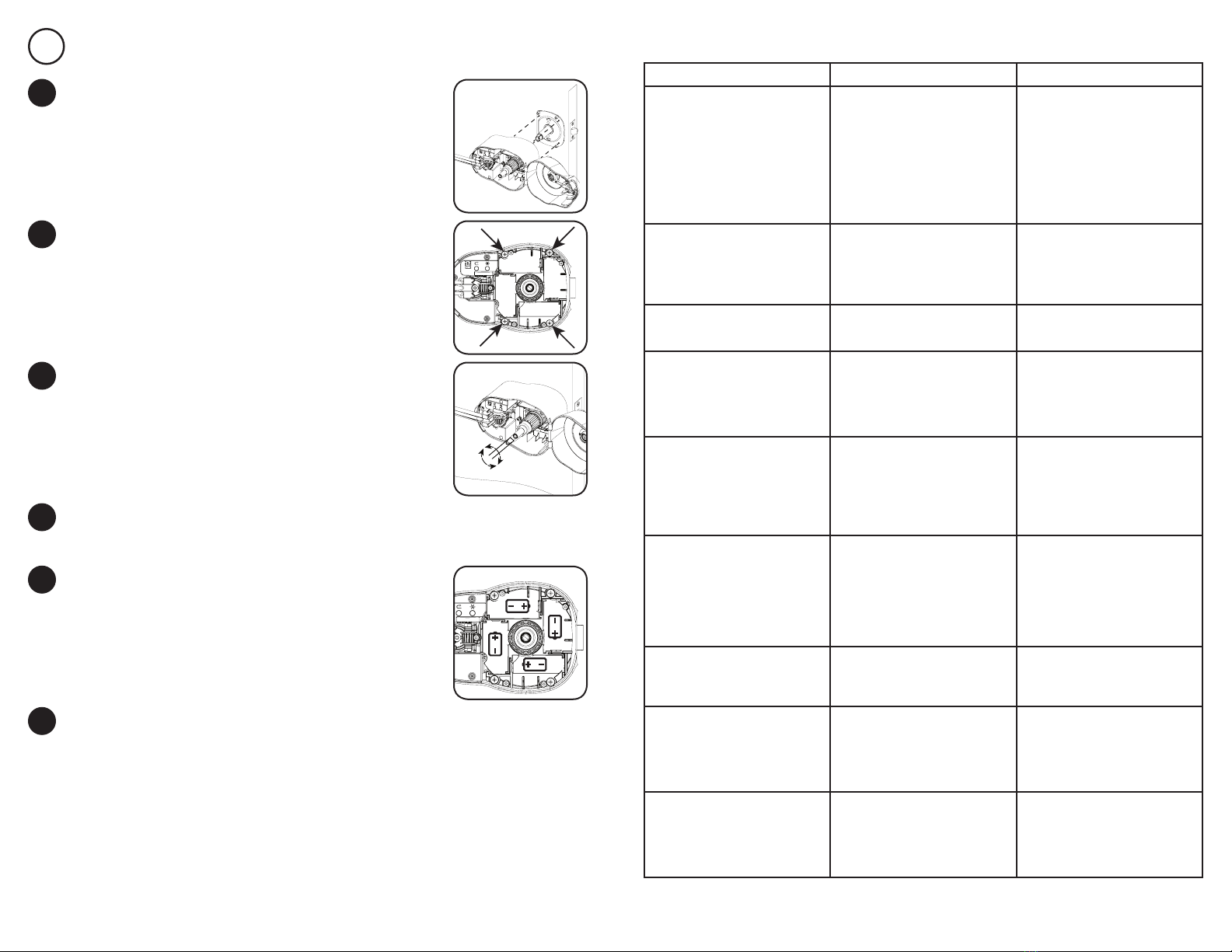
Install the 5/8” (16 mm) pan head machine
screws (Qty. 4) into the hygienic handle holes
(Figure 11). These screws will fasten the handle
to the mounting plate. Do not use a power drill
for these screws to ensure you do not OVER
tighten the screws and damage the mounting
plate threaded inserts.
c11
Pūrleve Hygienic Door Handle installation complete. To install a Pūrleve
#1005 Hygienic Rell, follow the instructions included in the rell box.
Ensure Pūrleve Handle is 'OFF' until the Pūrleve #1005 Hygienic Rell is installed.
g
Install included C Size batteries (Qty. 4)
(Figure 13).
f13
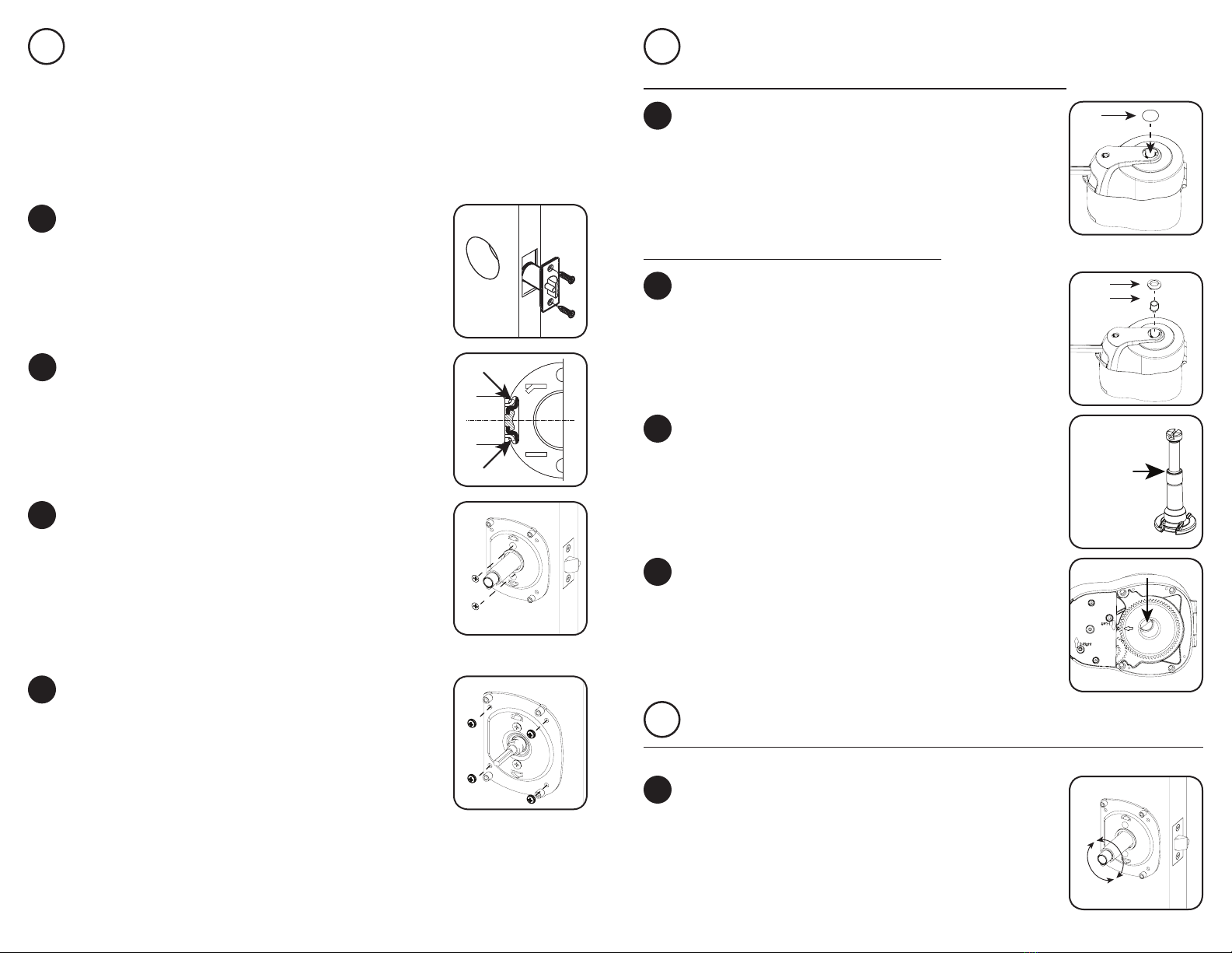
Using a at head screwdriver, rotate the head
of the push button connector clockwise until
the shoulder of head is ush with the top of the
metal tube inside the handle. Only push lightly
on the button connector (Figure 12). See Figure
7 for 'shoulder' visual.
d12
eClose Hygienic Handle Cover. Push in the Push Button to test the
locking mechanism. If needed, adjust the Push Button Connector in or out
until cover button functions smoothly.
Place the Pūrleve Handle onto the mounting
plate, previously installed. Ensure the 4 holes on
the backside of the Pūrleve Handle match with
the 4 threaded inserts on the Mounting Plate.
Ensure the Handle is facing AWAY from the
edge of the door (Figure 10).
b10
Electronic Functions and Instructions
FUNCTIONS INSTRUCTIONS RESULT
Turn Unit 'On' with infrared (IR)
Place the switch to 'ON - 1' setting.
Note A: Infrared recommended
when handle rst installed or if
significant vandalism in washroom
Note B:IR could be problematic in
some washroom lighting
environments.
Note C: 2 Second Sleeve Advance
Delay upon releasing hand from
handle and IR
When hand placed over or around
the handle the sleeve will stop and
a Green LED will be lit. When hand
removed, the sleeve will start and
the Green LED will turn OFF and
sleeve cycle will complete.
Turn Unit ‘On’
without Infrared (IR)
Place the switch to 'ON - 2' setting.
Sleeve will continue to run if hand
in view. Note D: 3 Second Sleeve
Advance Delay upon releasing
handle.
To test push down the handle
and Release Handle to advance a
sleeve.
Turn Unit ‘Off’ Place the switch to 'OFF' setting.
Unit is not powered. To test, push
down and release the handle to
ensure no sleeve activity.
Low Battery Indicator
To check if the dispenser is in a
'LOW' battery life status, simply
push down the handle and release.
Note E: Only Use this function if a
requirement.
1. If the batteries are low in energy,
the Red LED will blink 5 times,
when the handle is released.
2. If still working, the batteries
should be replaced with the next
refill.
Low Refill Indicator
To check if the dispenser is in a
'LOW' rell status, push down or
pull the handle and release.
1. If the rell is 'LOW' (estimated
250 sleeves remaining) the Yellow
LED will blink 5 times with each
advancement of the sleeve.
2. The 'LOW' rell indication will
continue until a new refill is placed
and the new count is activated.
Activate Low Refill Indicator
for New Refill
Turn Unit 'On' and push down or
pull handle. As the sleeve advances,
push the 'ARROW' button for 5
seconds or until the Green LED
begins to blink, then release.
Note F: To ensure proper counts,
only activate this function with a
NEW REFILL.
The Green LED will blink 5 times.
De-Activate Low Refill Indicator
Pull or Push Down the Handle. As
the sleeve advances, PUSH the
Star button for 5 seconds or until
the Yellow LED begins to blink.
The Yellow LED will blink 5 times.
Low Battery Indicator -
Demonstration
Slide to 'ON - 1' pull or push down
and release the handle. As the
sleeve is moving, PUSH and HOLD
the 'STAR' and 'ARROW' button
until the Red LED begins to blink,
then release the button.
The Red LED will blink 5 times.
Low Refill Indicator -
Demonstration
Slide to 'ON - 2' pull or push down
and release the handle. As the
sleeve is moving, PUSH and HOLD
the 'STAR' and 'ARROW' button
until the Yellow LED begins to
blink, then release the button.
The Yellow LED will blink 5 times.

Optional Accessories
Required Accessories
#1003: Coin Turn Lever Hardware - No key required to release
lock on hardware.
#1014: Keyed Lever Hardware - Key used to unlock hardware.
#1005: Pūrleve Rell Cartridge
#1012: Pūrleve Industrial Door Closure
#1016: 2 - 3/8” (60 mm) Latch (Use with Product #1003 -
Pūrleve Coin Turn Hardware)
#1017: 2 - 3/8” (60 mm) Latch (Use with Product #1014 -
Pūrleve Keyed Hardware)
Sold Separately
Note 11: One of the following two hardware sets is required for a
Pūrleve Hygienic Door Handle (#1002) installation: #1003 or #1014
111 W. Olive Street, Glendale, WI 53212
1.877.PURLEVE | www.purleve.com
A cleaner world is within reach.
v - 12
Table of contents
Other Purleve Door Lock manuals