1124465-X2-K 2
INSTALLATION
How To Install The Faucet
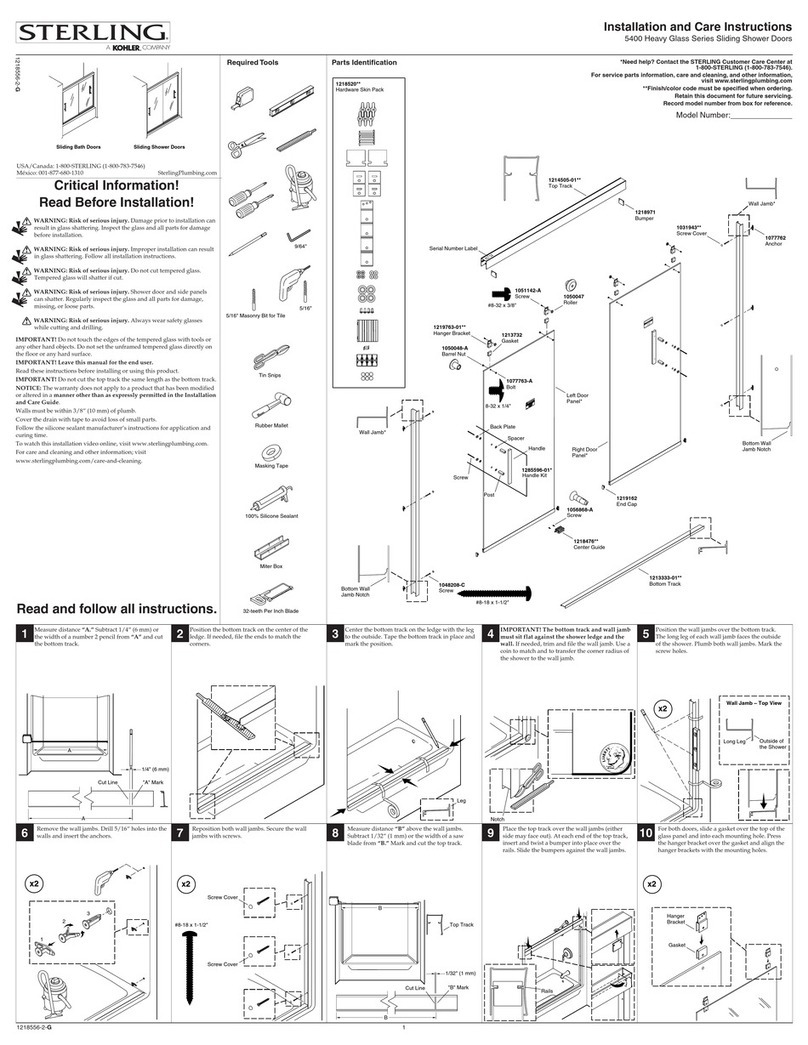
To perform installation, installer must
provide G1/2˝ female supply fittings(1),
spaced 150mm apart and level. The
supply fittings should be vertical and not
beyond the finished wall. Hot supply pipe
must be located on the left.
Flush the water supply pipes thoroughly
to remove debris.
Install the two offset connectors(2) into
the hot and cold supply pipes. Use
appropriate thread sealants or thread
tape on pipe threads.
Adjust the center-to-center distance
between the connectors to 150mm and
level. Thread the escutcheons(3) onto the
connectors until they are against the
finished wall.
Put the washers(4) into the nuts(5),
thread the nuts to connectors. Tighten
the nuts with strap wrench or soft cloth
between product and regular wrench.
1124465-X2-K 3
How To Install The Handspray
And The Hose
Tighten 500mm length hose(20) to the
outlet(21) and the connector(22) with two
washers(19).
Turn the diverter handle(23) to the vertical
upwards and run hot and cold water for
one minute to remove any debris.
Tighten 1500mm length hose(26) to the
connector(25) with filter washers(24-1).
Put the restrictor(27) into the handspray
(28) inlet. For 12947X-7 & 72675X-7,
72677X-7 tighten the hose(26) to the
handspray (28-2) or (28-3) with filter
washer(24-1). For 12950X-7, tighten the
hose(26) to the handspray(28-1) with the
washer(24-2, thickness 5mm).
28-2
23
26
24-1
24-1
25
20
19
21 22
19
27
27
28-1
24-2
2
1
150mm
Hot
Cold
3
4
5
How To Install The Slide Bar
Select a location in vertical wall to install shower
column according to rough-in dimensions.
Drill the lower hole to install a anchor as anchors(6)
diameter in the vertical position in the finished wall.
Press a anchor into the hole. Secure the base(9) by
the self-tapping screw(7) with the washer(8).
13
7
6
7
8
8
11
9
16
10
17
12
15
14
18
Ø30mm
6
Center Point
Base Diameter
ROUGH-IN DIMENSIONS
12947X-7/72675X-7 12950X-7/72677X-7
Ø203.2 (8˝)
400
809
62
G1/2˝ G1/2˝
34
Finished Floor
Ø203.2 (8˝)
400
809
62
G1/2˝ G1/2˝
1000~1100 (A)
34
150 15
25~28
G1/2˝
68
G1/2˝
Ø65
1098~1298
1108~1308
749~949
1000~1200 (A)
1098~1298
1108~1308
899~1099
Three-way Handspray
Handspray
G1/2˝
G1/2˝
500
G1/2˝
G1/2˝
1500
*Dimensions are approximate.
*ขนาดระยะแสดงคาโดยประมาณ
*Unit: mm
*หนวย: มม.
Finished Floor
ระยะการติดตั้ง
Rehearse the slide bar kit(10) installation
for the upper anchor mounting location
determination. Slide the base(11) onto the
connector(12) that insert into the base
about 26mm. Screw the screws(14) into
the base(11) with the hex wrench(13), and
tighten them.
Install the diverter body(15) onto the
base(9). Place the diverter body and the
base(11) against the finished wall. Mark
the diameter of the base(11) with a pencil.
Remove the slide bar kit. Loosen the
screws(14) with the hex wrench (NOTE:
Don’t lose the screws.), remove the
base(11). Mark the center point of the
base diameter with a pencil.
Drill a hole on the center point as anchors
(6) diameter. Press a anchor into the hole.
Secure the base(11) by the self-tapping
screw(7) with the washer(8), and make
sure two screw holes of the base(11)
vertically downwards.
Remove and discard the guard from the tube kit(16),
then install it into the slide bar kit. Install the nut(17)
onto the tube kit with soft cloth between internal hole of
the nut and the tube kit. Then screw the nut onto the
slide bar kit with strap wrench or soft cloth between the
nut and regular wrench.
Install the connector(12) and the diverter body(15) to
the base, and place the diverter body against the
finished wall, and the connector insert into the
base(11) about 26mm.
Screw the screw(18) into the diverter body with the hex
wrench, and tighten it. Tighten the screws(14) with the
hex wrench
ระดับพื้นหอง ระดับพื้นหอง
หัวฝกบัว 3 ระดับ
ฝกบัว
วิธีการติดตั้งกอกนํ้า
เพื่อการติดตั้งที่สมบูรณ ผูติดตั้งตองติดตั้งขอตอ
ทอน้ำดีสำหรับน้ำรอนและน้ำเย็นขนาด G 1/2" (1)
โดยทิ้งระยะหางระหวางกัน 150 มม.
ซึ่งตัวขอตอจะตองไดระนาบเดียวกับผนังและ
ไมยื่นออกมานอกผนัง โดยใหทอน้ำรอนอยูทาง
ดานซายมือ
เปดนํ้าเพื่อลางเศษสิ่งสกปรก
ติดตั้งขอเยื้อง(2) เขากับขอตอน้ำรอนน้ำเย็น
โดยใชเทปพันเกลียว
ปรับระยะหางของจุดกึ่งกลางของขอเยื้องใหหางกัน
150 มม. สวมฝาครอบ(3) เขากับขอเยื้อง
จนกระทั่งชิดกับผนัง
ใสแหวนรอง(4) เขากับนอต(5) แลวขันขอตอใหแนน
โดยใชประแจแบบสายรัดหรือใชผานุมรองระหวาง
ผลิตภัณฑและประแจกอนหากขันดวยประแจ
วิธีการติดตั้งกานฝกบัว
กำหนดจุดติดตั้งบนผนังที่ตองการติดกานฝกบัว โดยดูจาก
ระยะติดตั้งของผลิตภัณฑ
เจาะรูดานลางเพื่อติดตั้งพุก(6) สวมฐานรอง(9)
ยึดฐานรองใหติดผนังดวยสกรู(7) กับแหวนรอง (8)
ปรับชุดราวเลื่อน(10) เพื่อติดตั้งตัวยึดกานฝกบัว
ดานบน โดยเลื่อนฐานรอง(11) เขากับขอตอ(12)
ใหสอดเขาไปในฐานรองประมาณ 26 มม.
จากนั้นขันสกรู(14) เขากับฐานรอง(11)
ดวยประแจหกเหลี่ยม(13) ใหแนน
สวมตัวปรับทางน้ำ(15) เขากับฐานรอง(9)
วางตัวปรับทางน้ำและฐานรอง(11) ใหชิดกับผนัง
ลากเสนรอบวงของฐานรอง(11) บนผนังดวยดินสอ
ถอดชุดราวเลื่อนออก คลายเกลียวของสกรู(14)
ดวยประแจหกเหลี่ยม (ระวังสกรูหลนหาย)
ถอดฐานรอง(11) กำหนดจุดกึ่งกลางของฐานรอง
ไวดวยดินสอ
เจาะรูใหเทากับขนาดของพุก(6) สวมพุกเขากับ
รูที่เจาะไว ขันฐานรอง(11) ใหแนนดวยสกรู
เกลียวปลอย(7) และแหวนรอง(8) ตรวจสอบ
ใหแนใจวา ตำแหนงของรูสกรูของฐานรอง(11)
เรียงกันเปนแนวดิ่ง
วิธีติดตั้งชุดฝกบัวสายออน
ประกอบสายออนขนาด 500 มม. (20) เขากับ
ทางน้ำออก(21) และขอตอ(22) พรอมแหวนรอง(19)
หมุนมือบิดปรับทางน้ำ(23) ใหชี้ขึ้นดานบน
เปดน้ำรอนและน้ำเย็นไวประมาณ 1 นาที
เพื่อชำระสิ่งสกปรกตกคาง
สวมสายออนขนาด 1500 มม. (26) เขากับขอตอ
(25) พรอมดวยแหวนตะแกรง(24-1) สวมตัวลด
แรงดันน้ำ(27) ดานลางของหัวฝกบัว (28)
สำหรับรุน 12947X-7 และ 72675X-7
ใหขันสายฝกบัว(26) กับหัวฝกบัว(28-2) หรือ (28-3)
พรอมแหวนตะแกรง(24-1)
สำหรับรุน 12950X-7 ขันสายฝกบัว(26) เขากับ
หัวฝกบัว(28-1) พรอมแหวนรอง (24-2, หนา 5 มม.)
รอน
เย็น
เสนผานศูนยกลางฐานรอง
จุดศูนยกลาง
การติดตั้ง
ความสูง
จากพื้น
ความสูง
จากพื้น
ถอดแผนกันฝุนของกานยึดหัวฝกบัวกานแข็ง(16) ออก
แลวติดเขากับชุดราวเลื่อน สวมนอต(17) เขาไปในกานโคง
โดยสอดผานุมๆ เอาไวระหวางดานในของนอตกับกานโคง
แลวจึงขันนอตใหแนน เหนือกานชุดราวเลื่อนดวยประแจ
แบบสายรัด หรือใชผานุมๆ รองระหวางประแจกับนอต
เพื่อปองกันรอยขีดขวนบนผลิตภัณฑ
ติดตั้งขอตอ(12) และตัวปรับทางน้ำ(15) เขากับฐานรอง
ดันตัวปรับทางน้ำใหชิดผนัง แลวสวมตัวขอตอเขากับฐานรอง(11)
เขาไปประมาณ 26 มม.
ขันสกรูตัวหนอน(18) เขากับตัวปรับทางน้ำดวยประแจหกเหลี่ยมใหแนน
จากนั้นจึงขันสกรูตัวหนอน(14) ใหแนนดวยประแจหกเหลี่ยม
229
G1/2˝
9
28 24
28-3
*The installation height (A) can be adjusted depending on customer’s requirement
*ความสูงในการติดตั้ง (A) สามารถปรับไดตามความตองการของลูกคา"
102
219
G1/2˝
Ø102
