purway Crystal Group PUR QUICK 7 400 GPD User manual

PUR QUICK 7 400 GPD
User manual
Bongartz GmbH - purway Crystal Group® | Damaschkestr. 10 | 28307 Bremen | Phone: +49 (0)4721 - 66 30 50 | E-Mail: [email protected]

1
CONTENT
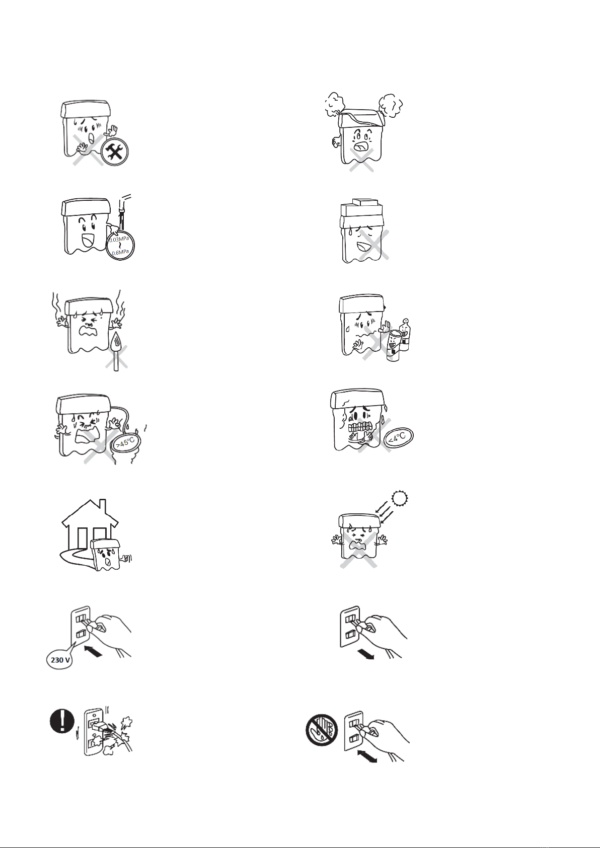
Safety instructions.............................................................................................................2
Introduction to the main functions of the reverse osmosis system....................................3
Technical specifications .....................................................................................................4
Computer control ..............................................................................................................4
Scope of delivery...............................................................................................................5
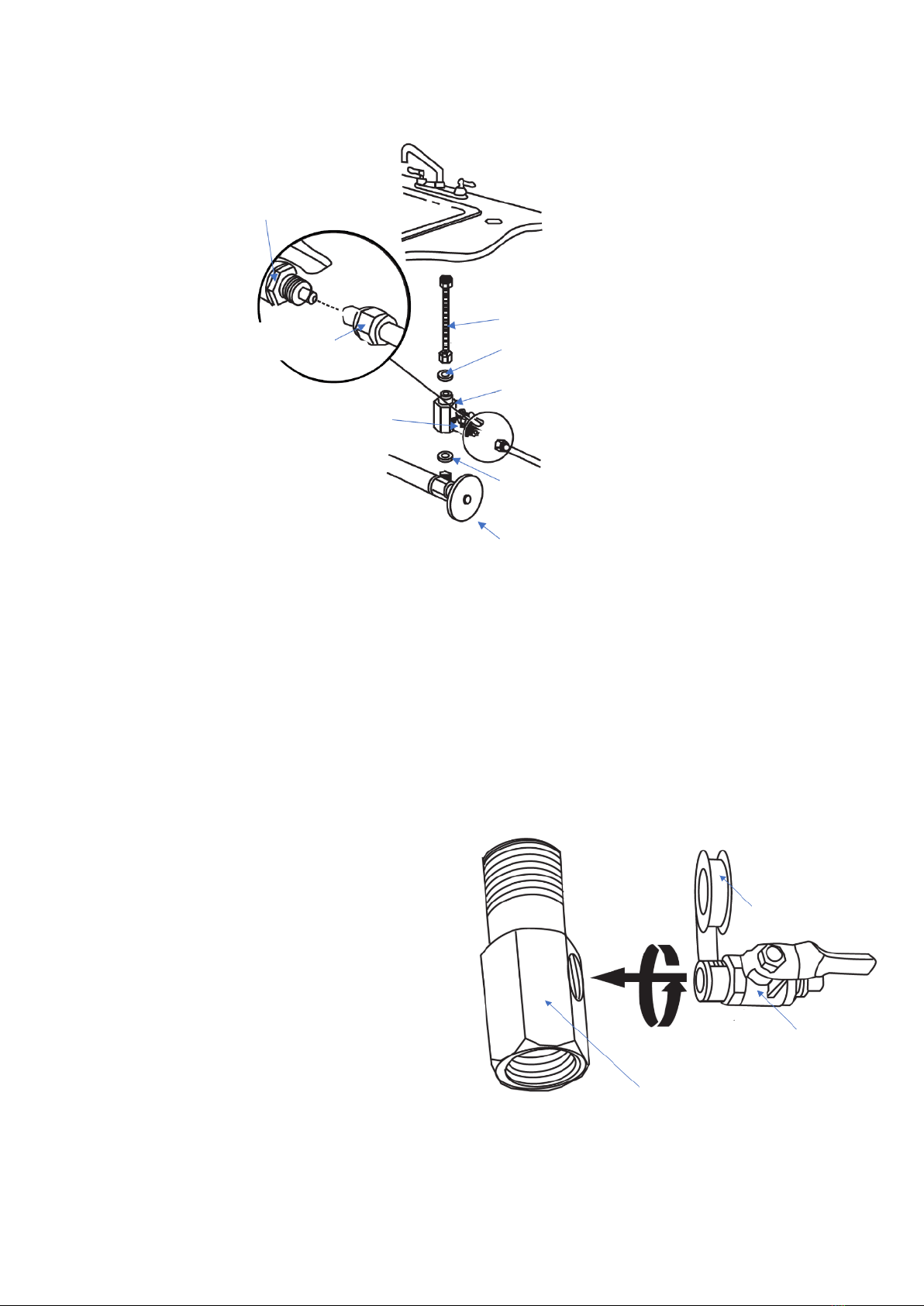
Installation instructions.....................................................................................................5
Initial start-up..................................................................................................................10
Maintenance and Care.....................................................................................................11
Filterchange.....................................................................................................................12
Troubleshooting ..............................................................................................................14
Dear Customer,
Thank you for purchasing the PUR Booster Quick 7 stages 400 GPD direct flow reserve osmosis water purifier
produced by purway Crystal Group©.
The reverse osmosis system in your possession is one of the most efficient and practical water treatment
systems currently available on the market.
To maximize the performance of the machine, please read the complete user manual before first use. Please
pay attention to our recommendations for the correct installation and proper maintenance.
If you have any questions about the product during installation or operation or if you need any assistance,
you can contact us by phone Monday to Friday from 9:00 a.m. to 3:00 p.m.
Our excellent support will be happy to help you with your request.
Telephone support:
+49 (0)4721 –66 30 50
E-mail-support:
Please have your invoice- or customer number ready when requested by our staff.

2
Safety instructions
Do not make any changes to
the device!
Do not cover the device!
Do not exceed the maximum
water inlet pressure of 4 bar!
Do not load the system with
heavy objects!
Do not use the device near
sources of fire!
Do not contaminate the
system with caustic or
corrosive materials!
The maximum inlet water
temperature is 45 ° C!
The minimum inlet water
temperature is 4 ° C!
Only use the device in closed
rooms!
Do not expose the device to
direct sunlight!
Only connect the device to a
voltage source of maximum
230 V AC!
Always pull out the power
plug as soon as you change
the filter or carry out
maintenance!
Do not damage the plug or
the electrical supply line!
Do not remove the power
plug with wet or damp
hands!

3
Introduction to the main functions of the reverse osmosis system
RO-membrane:
0,0001 µm effective filtration of
bacteria, viruses, heavy metals,
pesticides, insecticides, residues,
and other harmful substances
Booster pump 600 GPD:
Increases the pressure in the membrane
housing to overcome the osmotic
pressure.
PP10 „Melt blown filter”:
10 µm filtration of sediments such as
rust, sand, dust, etc.
GAC granular activated carbon filter:
Filtration of chlorine and organic
ingredients.
CTO activated carbon filter:
5 µm filtration of the finest particles
and chemical residues.
UF fine filter 0,02 micron:
0.2 µm filtration of very fine particles.
T33 activated carbon post filter:
Improves the taste of the water and
keeps it fresh.
Mineralization filter:
Doses calcium, magnesium and sodium.
Combination valve:
Controls the concentrate flow rate
during operation and flush modes.
Inlet solenoid valves:
Controls the system's water flow.
Manometer:
Measuring range 0 –1,6 MPa and 0
–220 psi.
High pressure switch (HPT):
The booster pump switches off
automatically when the pressure is
reached
Check valve:
Prevents a backflow of the permeate
in standby mode
Low pressure switch (LPT):
The booster pump switches off
automatically when the flow pressure
falls below the minimum.
Wastewater solenoid valves
Inlet solenoid valves
1
5
2
3
4
6
RO
HPT
LPT

4
Technical specifications
Computer control
In the case of critical messages, the computer control also emits an acoustic warning tone!
Voltage UN
230V AC 50 Hz/60 Hz - 24V DC
Rated power PN
75 W
Rated power standby PN
< 1W
Recommended water supply pressure pEintr
1 –4 bar
Operating pressure pBetr
8 bar ± 0,5 bar
Water temperature ϑEintr
4 - 45 °C
Maximum input water quality TDS QmaxEintr
≤500 ppm
Maximum RO water production volume
≤1100 ml/min
Flushing
Automatic and manual flushing
Protection class DIN EN 61140
Protection class II (protective insulation)
Recommended water quality
Tap water according to DIN2000
RO membrane
3012-400 GPD
Wastewater ratio
1:1
Installation dimensions
54 cm x 39 cm x 19 cm (h x w x d)
Weight (electrical device)
8,8 kg
Dimensions (electrical device)
49 cm x 37 cm x 19 cm (h x w x d)
Supply
The system is in production mode.
Flush
A flush routine is carried out.
Full
The system is filled and ready for operation
Water Lack
Low pressure switch has detected an inlet pressure that is too low.
Overhaul
The device is switched off due to overheating.
Strong Washing
Button: triggers a flush routine when pressed.
Power
The LED display signals that the system is being supplied with power.
Flushing process
The system flushes automatically as soon as the system is connected to the
power supply and at the beginning of a withdrawal if there is a standstill of > 2
hours. A flushing process takes about 30 seconds, and this increases the useful
life of the membrane.

5
Scope of delivery
•1x Reverse osmosis system PUR QUICK 7 400 GPD including pre-installed filters
•1x User manual PUR QUICK 7 400 GPD
•1x RO membrane model 3012-400
•1x Drain clamp for 1/4“ tube
•1x 3-way inlet valve with washer 1/2" and 3/8”
•1x Ball valve 3/8“ tube-1/4” male thread
•1x Spanner for membrane housing
•2x L-adapter 1/4“ tube-1/4“ male thread
•2m Tube 3/8“
•2m Tube 1/4"
•1x Teflon tape
•1x Stainless steel faucet
•1x Angle plate
•1x Aquastop leak sensor with two inserts
Installation instructions
•Please read the operating instructions carefully and be sure to follow the instructions and
information.
•If the device or its components are damaged, please contact the supplier or a specialist. We are not
liable for any damage caused by improper handling.
•Make sure that the installation site is tidy and that there is enough space.
•Be sure to turn off the water and power supply before starting the installation!
•In case of doubt, have the installation carried out by a specialist or a specialist company!
1. Preparation for installation and required tools.
Screwdriver
Wrench
Cutter
Drill
6 mm + 12 mm
Drill bit

6
2. Use of quick-change adapters
Assembly
Release
Remove the blue safety clip.
Remove the blue safety
clip.
Push the tube over a
constriction (seal) into the
connector (approx. 8mm).
Push the front ring
towards the connector
with your thumb and index
finger.
Pull the tube out a little and
attach the blue safety clip.
Carefully pull out the tube.
3. Connection diagramm
The "Pure Water" and "Wastewater" connections are secured with transport plugs. These must be removed
before the hose is connected. To unlock, see " Use of quick-change adapters".
1/4"
“
3/8“
1/4"
“
Aquastop leak sensor

7
4. Installation of the water supply
4.1 Shut off the water supply.
4.2 Release the flex tube of your faucet in the cold water and screw the 3-way inlet valve to the water pipe.
4.3 Ensure a correct fit of the washers.
5. Install the ball valve to the reverse osmosis system.
5.1 Wrap Teflon tape around the male thread of the
ball valve and screw it into the 3-way inlet valve.
5.2 Take the 3/8“tube and carefully cut it to the
desired length with the cutter. Make sure that
you do not squeeze the tube end when cutting
because it can lead to leaks.
5.3 Guide the union nut over one end of the
3/8“tube, push the tube over the broadening on
the ball valve and fasten the union nut.
Ball valve
Screw nut
Connection faucet
Washer
3-way inlet valve
Ball valve
Washer
Inlet water valve
3-way inlet valve
Ball valve
Teflon tape

8
6. Installation of the faucet
6.1 Mark the place where you want to mount your
osmosis faucet.
6.2 Use a drilling machine to drill a 12 mm diameter
hole through the sink or worktop.
6.3 Guide the base and the white rubber seal over the
threaded rod and place the fitting in the hole in the
worktop or sink.
6.4 Guide the black washer onto the threaded rod and
secure the fitting by hand-tightening the wing
screw.
6.5 Secure the fitting by hand-tightening the screw nut.
6.6 Put the screw nut and the conical sealing washer
on the ¾ "tube and now insert the tubular pin seal
with the narrow end into the opening of the ¾"
tube.
6.7 Pull the conical sealing washer onto the part of the
tube widened by the tube seal until it can no longer
be moved.
6.8 Now insert the tube into the opening of the thread of the faucet and fasten the tube by turning the screw
nut onto the thread.
6.9 Connect the tube to the pure water outlet of your reverse osmosis system by inserting it into the tube
quick release and letting it click into place.
Thread
Tube pin seal
Conical sealing washer
Srew nut
¼“ Tube

9
7. Installation wastewater
6.1 Drill a 6 mm hole above
the siphon bend.
6.2 Mount the supplied drain clamp with
the seal on the hole and tighten the screws
with a screwdriver.
6.3 Insert the wastewater
tube into the quick-
change adapter.
8. Installation Aquastop leak sensor
An Aquastop leak sensor with two separate inserts is included in the scope of delivery for further
protection against leaks. An insert is placed in the mount and swells as soon as it gets in contact with
water. This opens the flap and immediately cuts off the water supply to the system. Store the extra insert
in a dry place.
Make sure that the leak sensor is installed on a dry location below the RO unit. First connect the 3/8" tube
of the water inlet to the leak sensor and run another 3/8" tube from the outlet of the leak sensor to the inlet
of your RO unit.
When installing the device for the first time, leave out the insert, as leaks can still occur. Use the insert only
after the installation has been completed and when the system is leakproof after the test run.
Store the tablets in a dry place and out of the reach of children and do not eat the tablet!
Einlasswasserventil der Wasserversorgung
Umkehrosmoseanlage
RO unit
Water inlet

10
9. Installation of the reserve osmosis membrane
9.1 Remove the tube from the L-adapter on the housing
lid and open it with the appropriate spanner.
9.2 Take the new membrane out of the packaging and
press the end with the two O-rings into the membrane
housing first (Pay attention to the installation direction
and make sure that the connection piece of the
membrane has two O-rings).
9.3 Screw the housing lid back on hand-tight and insert the
tube into the L-adapter.
Initial start-up
Please make sure that the faucet of the reverse osmosis system is closed when the system
is started up for the first time, so that the system can perform an automatic flush after
plugging in the power switch. This ensures that any possible coal dust from the prefilters
will be flushed out and does not reach the membrane!
Usage hint
To prevent microbial contamination on the membrane during storage and transport, the membrane was
coated with a light protective solution. Therefore, dispose of the first 50-100 liters of osmosis water and do
not use it as drinking water.
When you start to operate the device, the TDS value of the water may be slightly increased. After a short
runtime, this value drops again and stabilizes.
If the inlet pressure is greater than 4 bar, please install a separate pressure reducer in the inlet of your
reverse osmosis system.

11
Maintenance and Care
Regular use of your system prevents it from drying out and possible hygiene problems.
If you are not going to use the device for a long time, please disconnect the water supply and the power plug
of your reverse osmosis system.
You should change the filter when you have reached the maximum service life or water volume.
The service life of six months based on DIN standard maintenance of drinking water systems DIN EN 806-5:
2012 must be complied with for reasons of hygiene.
Filterstage:
Water volume
Useful life
1
PP 10 µm
3000 –4000 𝑙
max. 6 month
2
GAC granular activated carbon filter
3000 –4000 𝑙
max. 6 month
3
CTO activated carbon block 5 µm
3000 –4000 𝑙
max. 6 month
4
UF fine filter 0,02 µm
3000 –4000 𝑙
max. 6 month
5
RO membrane 3012-400
7000 –9000 𝑙
max. 24 month
6
T33 post activated carbon filter
3000 –4000 𝑙
max. 6 month
7
Mineralization filter
3000 –4000 𝑙
max. 6 month
In addition, you should consider changing early if the following situations arise:
▪Bad water quality (Taste changes, the TDS value of the water increases).
▪Noticeable reduction in production volume.
▪Pressure fluctuations, high indicated pressure (> 10 bar).

12
Filterchange
1. Installation Twist-Change-System prefilters:
Before you start changing the filter, disconnect the water supply to your RO unit and pull the 230 V power
plug out of the socket! When the system is empty and depressurized, the filter bowls can be opened more
easily.
1.1 Loosen the filter cartridge by turning it 90 ° to the left. Pull the filter off downwards.
1.2 Unpack the new filters and pay attention to the correct order during installation, in flow direction from
right to left PP - GAC - CTO - UF.
1.3 Check the correct seating of both O-rings. Moisten them with a food grade lubricant.
1.4 Push the filter cartridge up and turn the filter 90 ° to the right until it locks.

13
1. Installation of the T33 post filter:
2.1 Loosen the quick-change adapters on the T33 postfilter and disconnect them.
2.2 Prepare the new cartridge by screwing the supplied ¼” L-adapter into the cartridge. Before doing this,
wrap the threads with sufficient Teflon tape to prevent possible leaks.
2.3 Insert the tubes into the quick-change adapters as usual.
2. Installation des Mineralisierung - Postfilter:
3.1 Loosen the quick-change adapters on the remineralising in-line cartridge and disconnect them.
3.2 Prepare the new cartridge by screwing the supplied ¼” L-adapter into the cartridge. Before doing this,
wrap the threads with sufficient Teflon tape to prevent possible leaks.
3.3 Insert the tubes into the quick-change adapters as usual.
The replaced filter cartridges cannot be reused. Please dispose of all used filter cartridges exclusively in the
residual waste!

14
Troubleshooting
Error
Reason
Solution
The device cannot be
switched on.
Device is not connected to the power.
Check the power supply.
power supply defective.
Contact customer service.
Blown fuse in the computer control.
Replace the computer controller.
The pump works
normally, but no pure
water is produced.
Inlet water solenoid valve is defective,
pure water cannot flow through.
Replace the solenoid valve.
A pre-filter is blocked.
Check the pure water and the
wastewater. If necessary, replace the
filter.
Check valve is blocked and does not
open.
Replace the check valve.
The reverse osmosis membrane is
blocked.
Clean or replace the membrane.
The wastewater valve is open without
authorization.
Replace the wastewater valve.
Wastewater is
constantly being
produced.
Inlet solenoid valve does not close.
Replace the inlet solenoid valve.
The device is filled
with water (standby
mode) and the pump
starts cyclically.
Check valve does not close.
Replace the check valve.
The device is losing water pressure.
Check for leaks
Pure water
production is very low
or does not flow at all.
Pre-filter is blocked.
Replace the pre-filter.
The reverse osmosis membrane is
blocked.
Clean or replace the membrane.
Inlet solenoid valve does not open.
Replace the inlet solenoid valve.
The booster pump does not have
enough pressure.
Measure the water pressure of the
pump and replace it if necessary.
Wastewater valve does not close.
Replace the wastewater valve.
The pump cannot be
switched off.
The high-pressure switch is defective.
Pull out the mains plug and replace the
high-pressure switch.
The connection terminal on the
control unit is wet.
Pull out the mains plug and pull out the
connection strip and dry it.
The electrical line to the high-pressure
switch is interrupted.
Pull out the power plug and reconnect
the electrical line.
A flashing 0 + F is
signaled with a
warning tone.
The low-pressure switch of the pump
has responded.
Check the inlet water pressure on
standby.
The inlet water valve to the osmosis
system is closed.
Open the inlet water valve to the
osmosis system.
The low-pressure switch is defective.
Replace low-pressure switch or bypass
it.

15
Declaration of conformity for the R & TTE directive 2016/35 / EC
Only for use in closed rooms
The manufacturer hereby declares that the device complies with the basic
requirements and all other relevant provisions of Directive 2016/35 / EC.
Bongartz GmbH - purway Crystal Group® | Damaschkestr. 10 | 28307 Bremen |Phone: +49 (0)4721 - 66 30 50 | E-Mail: [email protected]
Table of contents
Other purway Crystal Group Water Filtration System manuals

purway Crystal Group
purway Crystal Group PUR QUICK 7 600 GPD User manual

purway Crystal Group
purway Crystal Group PUR Quick 6 UF User manual

purway Crystal Group
purway Crystal Group purway User manual

purway Crystal Group
purway Crystal Group PUR Smart 800 PRO User manual

purway Crystal Group
purway Crystal Group PUR Smart 600 GPD User manual
Popular Water Filtration System manuals by other brands

Mega
Mega Filter Max Series user manual

Premier
Premier CT-1 Installation, operation and maintenance manual

OVIO
OVIO OHC-7000D user manual

US Water Systems
US Water Systems Greenwave Plus 385-GWP-1000-UV owner's manual

Waterway
Waterway pro clean plus owner's manual

Aquaox
Aquaox FLECK 5800 XTR2 Quick start manual