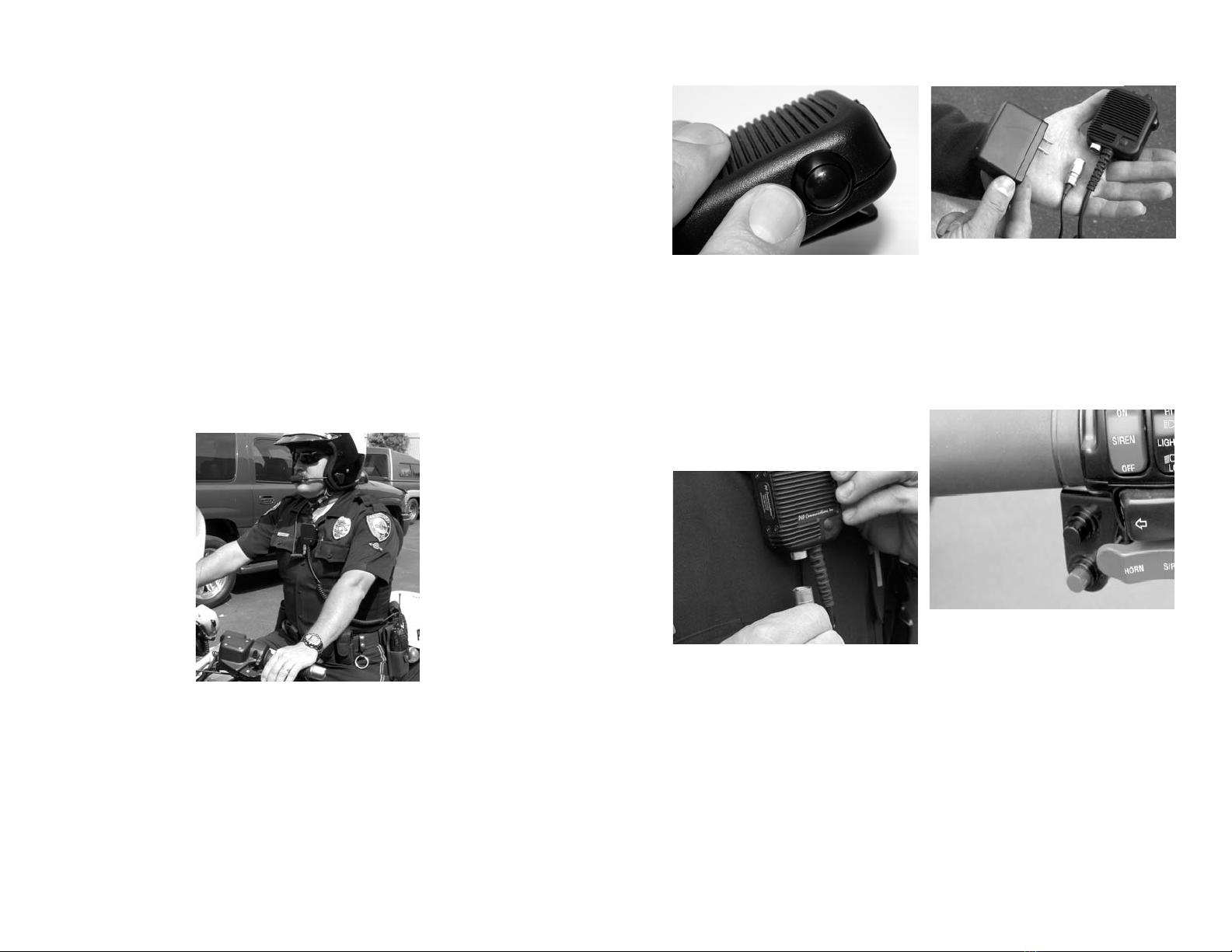
INSTALLATION
1) Attach accessory connector to
portable radio.
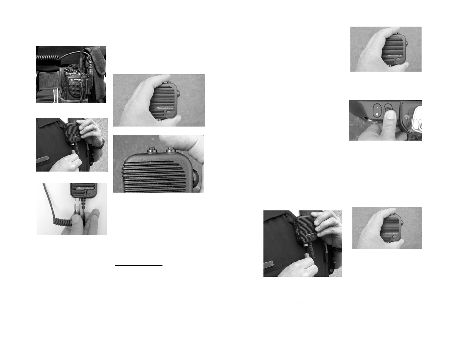
Helmet
Connection
NOTE: The helmet connector is
polarized so that it must be rotated
to the proper position before it will
snap into place. When properly
oriented, the coils in the cable
should lay against the officer’s
uniform (just above the badge if
worn at the lapel).
NOTE: Use this orienting proce-
dure to simplify connecting the
helmet to the shouldermic.
2) Connect Helmet.
3) Select POWER ON/OFF MODE:
The wireless transceiver in the shouldermic may
be configured for “auto power-on” mode or
“manual power-on” mode using the black
“Power on-off” switch:
NOTE: Shouldermics are shipped from the
factory pre-programmed for auto power-on, and
it is recommended to use the auto power-on
mode during normal operation:
“Auto power-on” mode causes the wireless
transceiver to power on automatically whenever
it is provided with battery power. Battery power
is applied to the wireless transceiver whenever
the helmet headset connection is made, and will
cause the transceiver to power on.
“Manual power-on” mode causes the wireless
transceiver to be powered on when the power
on-off button is pressed at the top of the shoul-
dermic. The helmet headset must be connected
to perform a manual power-on. To perform a
manual power-on, connect the headset and press
and hold the power on-off switch for 2-3 sec-
onds until the small status LED lights. Release
the switch.
Remote
PA
Power
on/off
Shouldermic without Remote PA Option.
Power
on/off
Shouldermic with Remote PA Option.
4) PAIR Shouldermic with Motorcycle:
After the power-on mode has been se-
lected and configured, the shouldermic
must be “paired” to a motor kit. Pairing
establishes a unique link between the
wireless shouldermic on the officer and
the motor kit on his bike that will not
interfere or be interfered with when other
wireless motorcycle systems come within
range. Once a pairing procedure has been
completed, it is “remembered” by both
the motor kit and by the shouldermic. A
new pair may be established at any time,
but until a new pair is established, the
shouldermic and the motor kit will re-
main “faithful”, responding only to their
mate. They will remember who their
mate is—even after having been powered
off.
A) Connect the helmet to the shoulder-
mic. The wireless device in the shoulder-
mic will power on (auto power-on mode)
and the LED will begin to flash.
NOTE: Helmet must be connected to the
shouldermic to power on.
B) Press the power switch for 2-3
seconds until the shouldermic LED
transitions to a solid color, then re-
lease. The wireless device will now
power off.
C) Verify that the motor kit is pow-
ered off, but has power connected to
it (ignition turned on or directly
connected to battery—same proce-
dure for power down as step B).
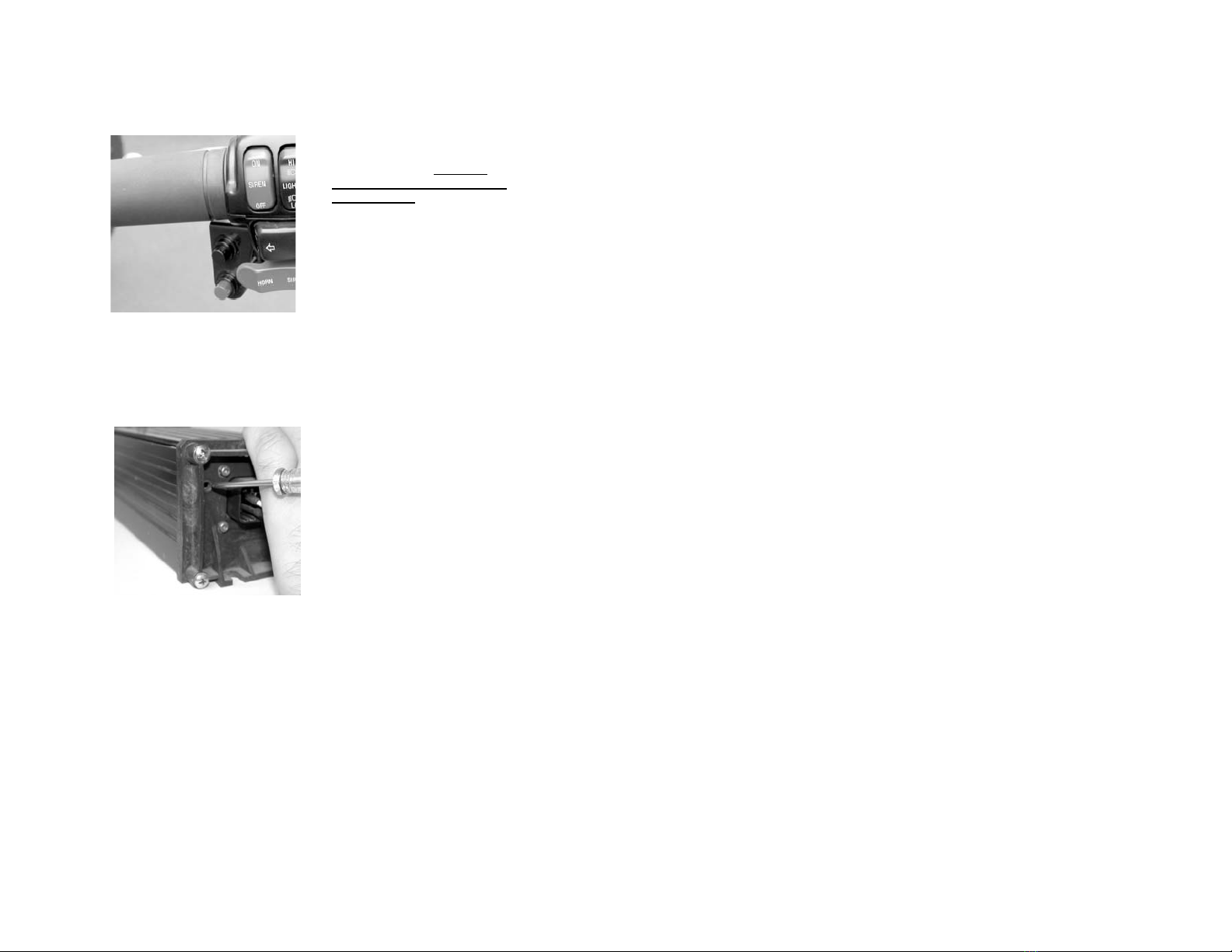
D) From the powered off condition,
press the power switch at the control
head as shown for 7-9 seconds until
the LED begins toggling red-green-
red-green, then release. The motor
kit has now powered on into pairing
mode and is searching for a mate.
E) From the powered off condition,
press the power switch at the shoul-
dermic as shown for 7-9 seconds
until the LED begins toggling red-
green-red-green, then release. The
shouldermic has now powered on
into pairing mode and is searching
for a mate.
NOTE: Within 15 seconds the wire-
less connection will be established
and both devices will display a green
status LED flash every 7 seconds,
indicating that they have been suc-
cessfully paired to each other.
NOTE: Reverse the 2-3 second proce-
dure to power off. The status LED will
transition to a solid color after the 2-3
second period, indicating that the switch
may now be released and the unit will
power off.
Changing power-on modes
Verify the transceiver is powered on.
Press the power switch quickly 3 times
within one second to place the transceiver
in manual power-on mode. Press the
power switch quickly 4 times within one
second to place the transceiver in auto
power-on mode.
PTT Status LED
Power on-off LED