manuals.online logo
Brands
  1. Home
  2. •
  3. Brands
  4. •
  5. PVP Communications
  6. •
  7. Motorcycle Accessories
  8. •
  9. PVP Communications Motor-One User manual

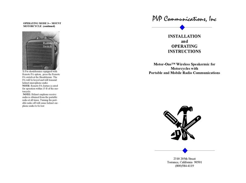
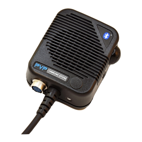
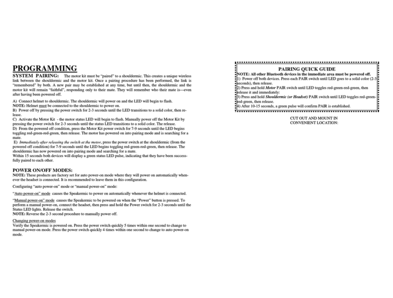
PVP Communications Motor-One User manual

Other manuals for Motor-One

4

Other PVP Communications Motorcycle Accessories manuals

PVP Communications Motor-One NXM Series User manual

PVP Communications

PVP Communications Motor-One NXM Series User manual

PVP Communications Motor-One User manual

PVP Communications

PVP Communications Motor-One User manual

PVP Communications Motor-One User manual

PVP Communications

PVP Communications Motor-One User manual

PVP Communications Motor-One User manual

PVP Communications

PVP Communications Motor-One User manual

PVP Communications Motor-One User manual

PVP Communications

PVP Communications Motor-One User manual

Popular Motorcycle Accessories manuals by other brands

SRC H-ADV150-04-01AL quick start guide

SRC

SRC H-ADV150-04-01AL quick start guide

DMD P1 owner's manual

DMD

DMD P1 owner's manual

GIVI Airflow AF1110 manual

GIVI

GIVI Airflow AF1110 manual

Suzuki 99143-00A1 000 Series installation instructions

Suzuki

Suzuki 99143-00A1 000 Series installation instructions

Cardo Systems FREECOM 4+ Pocket guide

Cardo Systems

Cardo Systems FREECOM 4+ Pocket guide

Shark S 700 user manual

Shark

Shark S 700 user manual

R&G CR0081 Fitting instructions

R&G

R&G CR0081 Fitting instructions

SRC B-TRK502-01-01-SL quick start guide

SRC

SRC B-TRK502-01-01-SL quick start guide

hepco & becker 6307520 00 01 manual

hepco & becker

hepco & becker 6307520 00 01 manual

HOMCOM AA0-077 user manual

HOMCOM

HOMCOM AA0-077 user manual

hepco & becker 6307558 00 01 manual

hepco & becker

hepco & becker 6307558 00 01 manual

SHOEI JO Instructions for use

SHOEI

SHOEI JO Instructions for use

Wunderkind Custom 106503-F15 Installation and safety

Wunderkind Custom

Wunderkind Custom 106503-F15 Installation and safety

Suzuki 57100-05881 installation instructions

Suzuki

Suzuki 57100-05881 installation instructions

SIKH HELMETS Y-61 quick start guide

SIKH HELMETS

SIKH HELMETS Y-61 quick start guide

Dräger HPS 3500 Instructions for use

Dräger

Dräger HPS 3500 Instructions for use

M-WAVE SKI manual

M-WAVE

M-WAVE SKI manual

Kuryakyn 6212 installation instructions

Kuryakyn

Kuryakyn 6212 installation instructions

manuals.online logo
manuals.online logoBrands
  • About & Mission
  • Contact us
  • Privacy Policy
  • Terms and Conditions

Copyright 2025 Manuals.Online. All Rights Reserved.

white
black
red
Motorcycle PA PTT Button—Assemble to handlebar bracket
red
black
Motorcycle Radio PTT Button—Assemble to handlebar bracket
Wires to 1/4 inch Harley Siren PA connector (pull back 1/4” jack and tie wrap to frame). Solder
wires to back of connector as follows:
MIC+ (RED wire) - TIP ( blue/pink ) (2014 and Newer Models: Pink /Brown)
PTT (WHITE wire) - RING ( red/pink ) (2014 and Newer Models: Pink /Green)
GND (BLACK wire) - SLEEVE ( white/pink ) (2014 and Newer Models: Pink /Black)
PA VOLUME:
Adjust helmet microphone PA transmit volume with a small flat screwdriver on the siren amplifier
(to access, remove Philips head at siren amplifier).
NOTE: An additional gain adjust is available in the Control Module if additional volume adjustment
is needed.
NOTE: When testing PA volume, make sure the siren speaker is directed to an open area to avoid
improper feedback.
NOTE: When testing PA volume, make sure the helmet microphone is on axis (not rotated) and held
close to the users mouth (within 1/4”).
PAIRING QUICK GUIDE
NOTE: All other Bluetooth devices in the immediate
area must be powered off.
1) Power off both devices. Press each PAIR switch until
LED goes to a solid color (2-3 seconds), then release.
2) Press and hold Motor PAIR switch until LED toggles
red-green-red-green, then release it and immediately:
3) Press and hold Shouldermic (or Headset) PAIR switch
until LED toggles red-green-red-green, then release.
4) After 10-15 seconds, a green pulse will confirm PAIR
is established.
CUT OUT AND MOUNT IN CONVENIENT LOCATION:
INSTALLATION DIAGRAM
Mount MODULE in rear radio box
NOTE: Do not install in metal enclosures
NOTE: Mount module away from speaker magnets
QUESTIONS? call us at 800-584-4119 Monday
through Friday, 7AM to 4PM Pacific Time, USA.
Removable tab
Removable tab
pairing
switch
5v
Pair LED
3v
KICK
MOB PTT
PA PTT
SQ
Pairing switch and led indicators
CONTROL
MODULE
Note: remove screws
to access PA volume
adjustment (12-turn
gain adjust)
Removable tab
Removable tab
PA volume
Battery +
Chassis ( do NOT connect to battery - )
To Ignition
PROGRAMMING
SYSTEM PAIRING: The motor kit must be “paired” to a shouldermic. This creates a unique wireless link
between the shouldermic and the motor kit. Once a pairing procedure has been performed, the link is
“remembered” by both. A new pair may be established at any time, but until then, the shouldermic and the motor
kit will remain “faithful”, responding only to their mate. They will remember who their mate is—even after hav-
ing been powered off.
A) Connect helmet to shouldermic. The shouldermic will power on and the LED will begin to flash.
NOTE: Helmet must be connected to the shouldermic to power on.
B) Power off by pressing the pairing switch for 2-3 seconds until the LED transitions to a solid color, then re-
lease.
C) Activate the Motor Kit by turning the Ignition on - the motor status LED will begin to flash. Manually power
off the Motor Kit by pressing the pairing switch for 2-3 seconds until the status LED transitions to a solid color.
Then release.
D) From the powered off condition, press the Motor Kit pairing switch for 7-9 seconds until the LED begins
toggling red-green-red-green, then release. The motor has powered on into pairing mode and is searching for a
mate.
E) Immediately after releasing the switch at the motor, press the pairing switch at the shouldermic (from the
powered off condition) for 7-9 seconds until the LED begins toggling red-green-red-green, then release. The
shouldermic has now powered on into pairing mode and searching for a mate.
Within 15 seconds both devices will display a green status LED pulse, indicating that they have been successfully
paired to each other.
POWER ON/OFF MODES:
NOTE: Motor Kits are factory set for auto power-on mode where they will power on automatically whenever
12VDC is applied to the Ignition wire. Turning Ignition off powers off the Module.
OPERATION
HELMET DISCONNECTED
1) Attach shouldermic to portable radio, turn the radio on.
2) Press shouldermic PTT switch to transmit.
3) Receive audio will play at the shouldermic speaker.
HELMET ATTACHED
1) Attach headset to shouldermic.
2) The following will occur:
A) The shouldermic speaker will mute and portable radio will play at the helmet earphones.
B) The helmet microphone will now be activated when PTT switch is pressed.
C) The wireless transceiver will power-on (auto power-on mode) and the status LED will begin flashing.
NOTE: The shouldermic contains a rechargeable battery that powers the internal wireless transceiver, and should
be charged each day. Charger connects at the headset connector port.
MOTORCYCLE HANDLEBAR SWITCHES
When paired (see PAIRING procedure) and powered on (see POWER ON/OFF MODES), the shouldermic and
motor kit status LED’s will display a green pulse, allowing the following:
1) The black handlebar PTT switch will activate portable radio transmit using the helmet microphone.
2) The red handlebar PTT switch will activate PA broadcast using the helmet microphone.
NOTE: Any PTT switch can be used at any time.
QUESTIONS? call us at 800-584-4119 Monday through Friday, 7AM to 4PM Pacific Time, USA.
INSTALLATION and OPERATING INSTRUCTIONS
Motor-One™ Wireless Portable Radio Interface Kit with PA
Broadcast for Police Motorcycles
United States Patents: 7,062,301 6,311,052 7,203,525