PXM PX314 User manual

MANUAL
AC+
Dimmer
24 x 3600W
PX314
R

TABLE OF CONTENTS
1. General description.............................................................................
2. Safety conditions.................................................................................
3. Front panel / Interface.........................................................................
4. Operation............................................................................................
4.1 Summary screen..................................................................
4.2 Channel summary screen....................................................
5. Programming......................................................................................
5.1 Menu....................................................................................
5.2 Setting the channel parameters...........................................
5.3 Program...............................................................................
5.3.1 Scene edit......................................................................
5.3.2 Scene copy....................................................................
5.3.3 Scene capture................................................................
5.3.4 Program edit..................................................................
5.3.5 Playback........................................................................
5.3.6 No signal........................................................................
5.4 Patch....................................................................................
5.5 Settings................................................................................
5.5.1 Curves...........................................................................
5.5.2 Admin.............................................................................
5.5.3 Art-Net...........................................................................
5.5.4 Fan.................................................................................
5.5.5 LCD................................................................................
5.5.6 LAN................................................................................
6. Installation and connection of the dimmer..........................................
6.1 Dimmer view after opening the door....................................
6.2 Connection scheme.............................................................
6.3 Installation steps..................................................................
6.4 External dimensions and arrangement of mounting holes...
7. DMX signal connection.......................................................................
8. Technical data.....................................................................................
Declaration of conformity........................................................................
3
3
4
5
6
6
7
7
7
9
9
10
10
10
10
11
11
12
13
14
15
15
16
16
17
17
18
19
20
21
21
22
Manufacturer reserves the right to make modifications in order to improve device operation.
PXM Marek Żupnik spółka komandytowa
ul. Przemysłowa 12
30-701 Kraków
tel.: 12 626 46 92
fax: 12 626 46 94
e-mail: [email protected]
Internet: www.pxm.pl
Rev. 1.0

PX314 AC+ Dimmer 24x 3600 W can be powered by three phases, and has an integrated system
fully protecting against the effects of reverse phases connection.
The device allows you to control 24 independent channels with a power of 3.6 kW each. The
dimmer enables you to control input signals from 6 different sources simultaneously, including:
- 2 DMX-512 lines,
- 3 Art-Net lines,
- 24 analogue inputs (option available to order).
The device has an integrated merger system with a possibility to select one of 13 priorities. The
advanced electronics allows you to address each output channel in any way, to select and edit the
driving characteristics (5 factory characteristics, 5 user's characteristics), and to set limits for
voltage and output current for each channel individually.
The device is equipped with the bulb heating system (10 levels) and control of the attached fuse
and broken circuit / burnt bulb. In addition, the user can define the dimmer response to the lack of
the driving signal. In addition to the basic options (ON, OFF, HOLD, SLOW TURN OFF), 64
stages and the program are available to be defined.
The integrated "PLL", "soft-start", "soft-on" and "even-off" systems assure reliable operation in
the most extreme conditions.
Direct detection of zero of the network and optical insulation of DMX input guarantee high
resistance to interference.
The device is equipped with an electronic measurement of current on each channel, current of
the entire dimmer, voltage at individual phases of the power, voltage frequency, and temperature
(separately for 2 groups of 12 channels). The dimmer is protected against reverse connection of
phases, has thermal protection and temperature control fans inside. Each group (12 circuits) has
a circuit breaker.
Each circuit has a16 A fuse breaker (characteristic C), circuit and overload protection. On
request, each output circuit can be equipped with a fuse-breaker.
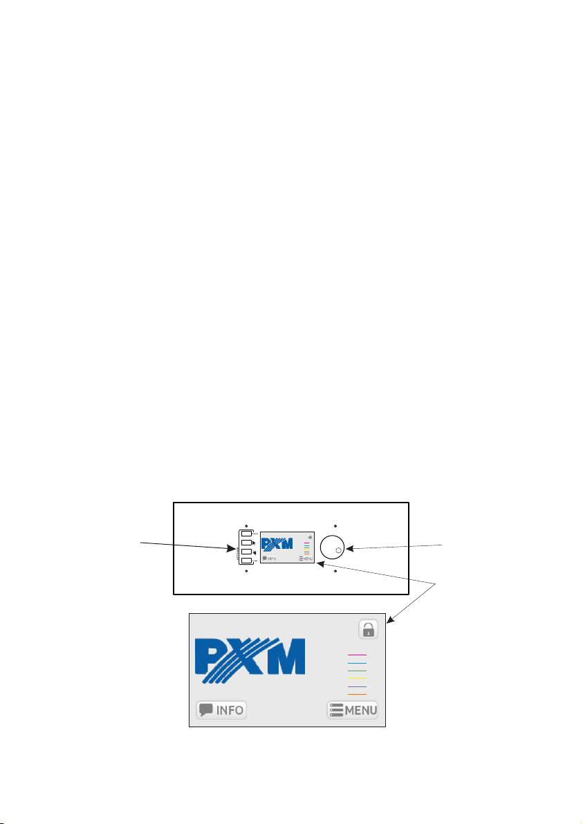
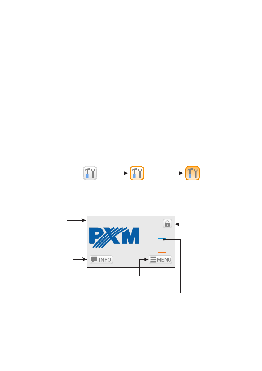
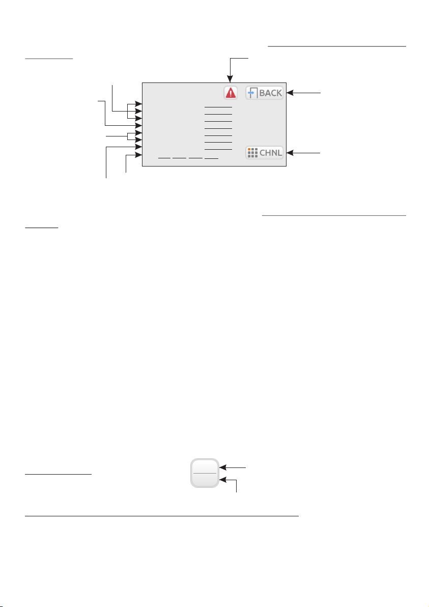
The dimmer is equipped with a touch screen, 4 keys and a knob with which you can define all the
parameters of the device. In addition, there is available an application to Windows, OSX and
Linux, which allows you to set all the parameters and monitor the status of multiple PX314
devices connected to one network.
The device is produced in the housing for wall mounting.
1. GENERAL DESCRIPTION
3
2. SAFETY CONDITIONS
PX314 dimmer is a device powered directly from the 230 V mains. Failure to observe safety
instructions may result in electric shock and pose a threat to life. Therefore, you should strictly
adhere to the rules outlined below:
1. Installation of the device, and in particular, connection of power, should be made by a suitably
qualified person, as described in the manual.
2. The device can be connected only to 3- or 5-wire installation (with a separate protective
conductor).
3. Protect all cables against mechanical and thermal damage.

3. FRONT PANEL / INTERFACE
The device is equipped with a colour touch display with a resolution of 480x272 px. During
operation, it displays basic information and possible warnings and errors. The displays also
allows you to set the parameters of the dimmer. You may be asked to give a password to enter the
settings menu.
4
4. In case of failure of any of the cables, it must be replaced with a cable of the same technical
parameters.
2
5. Use only 3-wire cables of not less than 2.5 mm for connecting devices to the dimmer.
6. Each receiver should be powered by a separate cable.
7. After installation, test the effectiveness of resetting all the equipment controlled.
8. All repairs that require the housing to be removed can only be carried out with power
disconnected.
9. The dimmer must be strictly protected against contact with water or other liquids.
10. Avoid sudden shocks, particularly dropping.
11. Do not connect dimmer with damaged (dented) housing to the power supply.
12. Do not operate the device in rooms with humidity above 90%.
13. The device must not be used in rooms with a temperature below +2 °C or above +40 °C.
14. Clean only with a damp cloth – the dimmer must be at this time completely disconnected
from the power supply.
NOTE!!!
1. Improper connection of the protective conductor (of yellow and green colour) creates the risk
of electric shock.
2. Improper connection of the neutral wire (of blue colour) will automatically turn off the dimmer
and start the buzzer.
3. It is also acceptable to power the dimmer with one or two phases.
display
KNOB
It is used to quickly change the numerical values in the text boxes and switch between successive
elements on the screen. Pressing the knob is equal to pressing the ENTER key.
knob
programming
keys
Px314 DIMMER NR: 1
DMX 1: 1
DMX 2: 1
ARTNET A: 1
ARTNET B: 1
ARTNET C: 1
ANALOG: 1
Px314 DIMMER NR: 1
DMX 1: 1
DMX 2: 1
ARTNET A: 1
ARTNET B: 1
ARTNET C: 1
ANALOG: 1

KEYS
The four keys on the left side of the screen help navigate the menus.
ź ENTER – it activates the selected item. If the selected item is a key – it presses this key, if a list
– it expands this list, if a text box – it starts to edit it.
ź NEXT, PREV – they are used to switch between successive items on the screen and select
values from the list and numeric fields.
ź ESC – it allows you to cancel the changes.
INTERFACE
During the preview of information and setting parameters on the screen, there are 3 types of
interactive elements: keys, text boxes and selection lists. Items can be selected directly on the
touch screen or by using the arrow keys. NEXT/PREV keys (or knob) are used to select the
next/previous item on the screen (item envelope becomes orange), the ENTER key is used to
activate the currently selected item (item envelope and background become orange). Activation
of the key causes it to be pressed, activation of the text box allows you to enter a new value,
activation of the selection list causes it to expand and display available options. When using the
touch screen, numeric values in the text boxes are added using the onscreen keyboard, NEXT
and PREV keys or the knob.
4. OPERATION
After starting the device, the display shows the start screen, including:
Start screen is visible to every user, without a password.
name and number
of the dimmer information whether the
device requires you to give
a password (the symbol of
a n o p e n o r c l o s e d
padlock), and clicking it
causes log out or log in
addresses of the first
channel (only inputs with
signal are visible)
summary screen
moving to [MENU] screen with available keys:
• CHANNELS
• PROGRAM
• PATCH
• SETTINGS
• BACK
Px314 DIMMER NR: 1
DMX 1: 1
DMX 2: 1
ARTNET A: 1
ARTNET B: 1
ARTNET C: 1
ANALOG: 1
selection activation
5

4.1 Summary screen
phase voltage
total current
t e m p e r a t u r e
(separately for 2
blocks of channels)
v o l t a g e
frequency
IP address of the device
key to return to the
main screen
error notification key (if any)
INFO
PHASE 1: V
PHASE 2: V
PHASE 3: V
CURRENT: A
TEMPERATURE 1: C
TEMPERATURE 2: C
FREQUENCY: Hz
IP: . . . key to return to the
channel summary
screen
Error notification key is displayed on the screen when one of the following errors is detected in the
dimmer:
ź DRIVER HIGH TEMPERATURE
ź CHNL FUSE MISSING
ź CHNL OVERLOAD
ź CHNL OPEN CIRCUIT
- warning about exceeding the maximum temperature set
in the FAN menu;
- error, no voltage on the phase (contact the service);
- error, internal error (contact the service);
- error, no communication with the unit (contact the service);
- error, thermistor damage (contact the service);
- error, thermistor is shorted (contact the service);
- error, channel is shorted (contact the service);
- warning, fuse is not enabled or one supply phase is missing
- warning, channel overcurrent;
- error, triac is shorted (contact the service);
- warning, open circuit or burnt bulb.
The messages are divided into errors and warnings – errors are shown in red and a warnings in
orange.
ź PHASE LOSS
źPHASE ERROR 1
źMODULE NOT RESPONDING
ź DRIVER TERMISTOR MISSING
ź DRIVER TERMISTOR SHORTED
ź CHNL OUTPUT SHORTED
ź CHNL TRIAC SHORTED
4.2 Channel summary screen
1
25%
The channel summary screen [CHANNELS INFO] shows keys corresponding to 25 output
channels.
Each key shows:
The colours of captions depend on the source of value on the channel:
•
•
•
•
violet – DMX 1
blue – DMX 2
green – Art.-Net 1
yellow – Art.-Net 2
channel number
current value on the channel
Pressing the [INFO] key takes you to the summary screen. This screen includes the following
information:
ź
ź
ź black – no signal
orange – Art.-Net 3
brown – analog input
6
NOTE: In the case of closing the output circuit, the dimmer automatically disconnects the circuit.
In this case, disconnect device from the power supply and check the cause of short circuit.

CHANNEL 1
MERGED VALUE: 0
MERGE: DMX1
DMX 1: 1
DMX 2: 1
ARTNET A: 1
ARTNET B: 1
ARTNET C: 1
ANALOG: 1
OUTPUT: 0,0 %
LOAD: 0,0 A
FUSE: OK
MAX POWER: 3,6 kW
Pressing one of the channel keys takes you to the corresponding channel summary screen. This
screen displays the following information:
val ue g ai ne d by
merging inputs (0-
255)
merge mode
addresses for
individual inputs
On this screen, there are also available the [NEXT] and [PREV] keys used to quickly navigate to
the next/previous channel and the [BACK] key used to return to the list of channels.
If the dimmer is connected to the application on a PC – all the information is also available on an
ongoing basis in the program.
value on the output
depending on the output
characteristics
channel load
fuse status
maximum power on the channel
5. PROGRAMMING
5.1 Menu
Pressing the [MENU] key on the main screen of the dimmer, takes you to the screen with available
keys:
CHANNELS
PROGRAM
PATCH
SETTINGS
- setting the parameters of output channels
- defining the scenes and program that can be activated in the
absence of DMX signal
- addressing inputs and merge mode for individual inputs
- other settings
5.2 Setting the channel parameters
After selecting [CHANNELS PARAMETERS], you can set the parameters:
SINGLE
RANGE
-
- collectively for the channel range
separately for individual channel
7

RANGE
POWER 100 %
MAX CURRENT 16 A
CURVE LINEAR
PREHEAT OFF
FROM 1
TO 1
If you select [RANGE], the following fields will be available on the screen:
reduction of output
p o w e r ( r a n g e
0-100%)
maximum current on
the channel (1-16 A)
input characteristics of the channel
range of channels for
which the parameters
are to be set
lighting the channel – 10
levels of channel lighting
to choose from: OFF,
LEVEL 1 - LEVEL 9
Pressing the [ESC] key exits the screen without saving your changes, press the [SAVE] key to
exit the screen and save your settings for all channels in a given range.
If you select the [SINGLE] option, the screen will display the keys for all output channels. Pressing
one of the channel keys takes you to the corresponding channel parameter screen:
CHANNEL 1
POWER 100 %
MAX CURRENT 16 A
CURVE LINEAR
PREHEAT OFF
[NEXT] and [PREV] keys allow you to quickly switch between successive channels. To save your
parameters, press [SAVE] before switching to another channel.
8
The user can select the following curves:
LINEAR – the value on the output is directly proportional to the input value,
EXPONENTIAL – exponential characteristics,
LOGARITHMIC – logarithmic characteristics,
ON/OFF – two-level characteristics,
REVERSED – the value on the output is inversely proportional to the input value,
USER 1-5 – 5 curves to be defined by the user.

5.3 Program
In the [PROGRAMMING] menu, you can program 128 scenes and a program that can be
activated in the absence of DMX signal. Scene is a static adjustment of the value at the output
channels. Program is a set of successive scenes.
The screen shows the following keys:
EDIT
SCENE
COPY
SCENE
CAPTURE
SCENE
EDIT
PROGRAM
PLAY
NO SIGNAL
– editing on of 128 scenes
– copying set values between the scenes
– capturing the current scene output status
– defining the order of scenes in the program
– scene or program preview
– defining the dimmer operation in the absence of DMX signal
5.3.1 Scene edit
SCENE 1
CHNL 1 0
Go to: 1
CHNL 2 0
CHNL 3 0
CHNL 4 0
CHNL 5 0
CHNL 6 0
RANGE
In Time: 00:00
Dur Time: 00:00
Scene edit screen includes:
number of currently
edited scene
field that allows you to go
to other, selected scene
list of output channels
together with the values –
user can set on the list the
values (within the range:
0-2 55) o n indi vid ual
channels
key makes it easy to simultaneously set the same value in the
selected range of channels
key to change times – allows
you to set the entry time and
duration of the scene; scene
off time is always equal to 5
seconds
When you select [EDIT SCENE], the application displays the screen for editing scene 1; in
addition, scene 1 occurs on the outputs.
[NEXT] and [PREV] keys – allow you to switch between the scenes. Transitions are made in a
linear way.
key to go to the successive
numbers of channels
9

5.3.2 Scene copying
Scene copying screen contains 2 fields: [FROM] and [TO] which allow you to specify the source
scene and the target scene between which the values are to be copied.
5.3.3 Scene capture
Scene capture option allows you to save current values on the output channels to the selected
scene.
Scene capture screen includes:
TO SCENE 1
CHNL 1 0
CHNL 2 0
CHNL 3 0
CHNL 4 0
CHNL 5 0
CHNL 6 0
In Time: 00:00
Dur Time: 00:00
CURRENT VALUES
scene number field in
which the user can enter
the number of scene to
which the captured
values are to be saved
current values on all channels,
which are to be saved
key to change times
[NEXT] / [PREV] keys – allow you to switch between the scenes.
5.3.4 Program edit
EDIT PROGRAM
STEP 1 – SCENE: 1
STEP 2 – SCENE: 1
STEP 3 – SCENE: 1
STEP 4 – SCENE: 1
STEP 5 – SCENE: 1
STEP 6 – SCENE: 1
STEP 7 – SCENE: 1
STEP 8 – SCENE: 1
adds the selected
scene to the program
as the next step
removes the selected
step from the program
The program edit screen shows a list of 64 steps and scenes corresponding to these steps.
"inactive" steps
active, defined step
5.3.5 Playback
The playback screen [PLAY] allows you to preview the created scenes and program. On the
screen, there are keys to play and stop the program and the field to select a scene, as well
as play and stop keys for the selected scene. The [BACK] key which exits the screen.
keys to go to the successive
numbers of channels
10

RANGE
DMX 1 1MERGE
DOUBLE PRECISION
FROM 1
TO 24
DMX 2 1
ARTNET A 1
ARTNET B 1
ARTNET C 1
ANALOG 1
SOURCE ADDRESS
DMX1
5.3.6 No signal
By using the [NO DMX SIGNAL] screen, you can program the operation of the device in the
absence of DMX signal.
Available options:
• ON – all channels will be enabled at 100%;
• OFF – all channels will be disabled;
• SLOW TURN OFF – there will be a slow blanking of all channels;
• HOLD – the last value present before the signal loss will be saved on the channels;
• SCENE – the selected scene will be displayed;
• PROGRAM – the program will be played.
5.4 Patch
The [PATCH] menu allows you to set the merge mode for inputs and DMX address on the various
inputs, as well as to determine whether the channel is controlled with double-precision (using two
DMX channels).
Settings can be changed separately for the selected channels [SINGLE] or in groups for a fixed
range of channels [RANGE].
Selecting [RANGE] takes you to the screen for group settings. This screen includes the following
fields:
starting address for each type of source (channels are addressed sequentially)
range of channels for which the
changes are to be made
selection list for the merge mode
Available values of the merge mode:
ź HIGH – the highest of values;
ź LAST – last value;
ź DMX1 – value from the DMX 1 input;
ź DMX2 – value from the DMX 2 input;
ź UNIVERSE 1 – value from the Art-Net 1 input;
ź UNIVERSE 2 – value from the Art-Net 2 input;
ź UNIVERSE 3 – value from the Art-Net 3 input;
ź is DMX1/DMX2 – value from the DMX 1 input, if there is a signal on it, if not – DMX 2 input;
ź is DMX1/DMX2 CAPTURE – if DMX 1 and DMX 2 are enabled, value from the DMX 1 input is
selected. If you disable DMX 1, value from the DMX 2 is selected only when it reaches
the DMX 1 input value. This mode prevents abrupt changes in values.
11

ź is DMX2/DMX1 – value from the DMX 2 input, if there is a signal on it, if not – DMX 1 input;
ź is DMX2/DMX1 CAPTURE – if DMX 1 and DMX 2 are enabled, value from the DMX 2 input is
selected. If you disable DMX 2, value from the DMX 1 is selected only when it reaches
the DMX 2 input value.
ź is DMX1/UNVRS 1 – value from the DMX 1 input, if there is a signal on it, if not – UNIVERS 1
input;
ź is DMX1/UNVRS 1 CAPT. – if DMX 1 and UNIVERS 1 are enabled, value from the DMX 1 input
is selected. If you disable DMX 1, value from the UNIVERS 1 is selected only when it
reaches the DMX 1 input value.
ź is UNVRS 1/DMX1 – value from the UNIVERS 1 input, if there is a signal on it, if not – DMX 1
input;
ź is UNVRS 1/DMX1 CAPT.– if DMX 1 and UNIVERS 1 are enabled, value from the UNIVERS 1
input is selected. If you disable UNIVERS 1, value from the DMX 1 is selected only when
it reaches the UNIVERS 1 input value.
ź ALWAYS ON – channel is always enabled.
Selecting [SINGLE] allows you to set the same options for individual channels.
5.5 Settings
The [SETTINGS] menu includes the following categories:
CURVES
ADMIN
ARTNET
FAN
LCD
LAN
– management of characteristics curves
– administrator settings
– Art-Net settings
– fan settings
– display settings
– network settings
12

Clicking on one of the keys takes you to the preview of the curve.
For pre-set curves, [COPY] and [BACK] keys are displayed next to the preview.
For user's curves, [EDIT] and [BACK] keys are available.
Pressing the [COPY] key displays the copy window, where you can determine to which user's
curve, and to what extent, the selected curve will be copied.
Pressing the [EDIT] key displays windows with 12 points for which you can enter values. The
curve will be drawn between the designated points. The curve can be created from 2-12 points.
NOTE: The first point of the defined curve must always have the x coordinate equal to 0.
Sample configuration of the user's curve:
1. From the [CURVES] menu, select the user's curve key, for example, [USER 1]
2. Press [EDIT], the application displays a table of 12 coordinates of the points between which the
new curve is drawn
3. Complete the table
13
CURVE: USER 1
63 127 91 255
25%
50%
75%
100%
0
23
46
69
92
115 75
0
75
50
75
50
x y x y
139
162
185
208
231
255 100
50
75
50
75
50
4. To save the settings, press [SAVE], a user-
defined curve appears on the screen
channel output
power [%]
channel input values
5.5.1 Curves
10 curves are available in the device: 5 preset and 5 user-definable. Preset curves can be
previewed and copied. User's curves can be edited.
The [CURVES] screen includes 10 keys for all the curves:
ź LINEAR,
ź REVERSED,
ź SWITCHED,
ź LOGARITHMIC,
ź EXPONENTIAL,
ź USER 1 - USER 5.

5.5.2 Admin
Category [ADMIN] contains the administrator settings:
ADMIN
DEVICE NR: 1
PASSWORD
ADMIN 1111
EXPERT 2222
USER 3333
DEFAULT CONFIG restoring the factory default configuration
setting the device number
by selecting this option, you can set the
access password
administrator, technician and user password
(a number in the range 0-9999)
device reset, the device stops in the bootloader
and it is possible to upload new software
To go to the program, click on any key.
NOTE: If an incorrect administrator password is entered ten times (in each case, the message
"NO ACCESS RIGHTS TO" is displayed), the device will be blocked and you will need to
contact customer service.
Switching between user accounts:
1. Click the button (located on the start screen of the panel, it will cause the user logout
2. Click again in the padlock key to display the login screen
3. Select the account that you want to log on and enter your password
4. Confirm
14
0
23
63
0
92
115 75
0
75
50
75
50
x y x y
139
162
185
208
231
255 100
50
75
50
75
50
Only the points for which the values on the x-axis are given incrementally are taken into account,
e.g.:
CURVE: USER 1
63 127 91 255
25%
50%
75%
100% entering a value of less
than 64 causes that
only the first three
points are taken into
account

No logging
User
Technician
Administrator
Start screen
ü
ü
ü
ü
Summary screen
X
ü
ü
ü
Channel preview screen
X
ü
ü
ü
Scene /
Program running
X
X
ü
ü
Channel setting
X
X
ü
ü
Program / Scene edit
X
X
ü
ü
Channel patch
X
X
ü
ü
Curve, fan,
display setting
X
X
ü
ü
Ethernet,
Art-Net settings
X
X
X
ü
User and password
management
X
X
X
ü
The device has 3 users whose access levels are shown in the table below:
5.5.3 Art-Net
In the [ARTNET] menu, there are address settings [SUBNET] and [PORT] which allow you to
select Univers for each of the three Art-Net input ports.
5.5.4 Fan
15
Thermal protection of the dimmer
The device is equipped with a built-in automatic power reduction system.
Dimmer monitors the temperature of channel groups; if the temperature of 65 °C is exceeded, the
output power is automatically reduced. This reduction is linear over the range 65-80 °C, i.e., if the
temperature of 80 °C is exceeded, the device will disable the channels.

FAN
MAX 60 C
MIN 20 C
MODE PROPORTIONAL
LCD
AFTER 5
SCREENSAVER
START SCREEN PROGRAMMING
5.5.5 LCD
The display menu includes the screen saver settings. You can determine whether the screen
saver is to be run, and if so, after what idle time and which of the screens is to be displayed after
the "awakening".
list of available start screens displayed after
device awakening:
ź INFO
ź LOGIN
ź MENU
ź PROGRAMMING
ź SETTINGS
ź START
time after which the screen saver is activated
(1-100 minutes)
screen saver activation
5.5.6 LAN
In the [LAN] menu, local network settings are available:
ź IP
ź MASK
ź GATEWAY
16
The following settings are available in the fan menu:
fan operation modes:
ź PROPORTIONAL – the air flow increases linearly
with the increasing temperature (between
the minimum and maximum temperature)
ź HYSTERESIS – the fan turns on and operates at
100% when the specified maximum
temperature is exceeded, and turns off
below the minimum temperature
ź ON – fan operates with maximum power
temperature at which the fan operates
with maximum power
temperature at which the
fan turns on
NOTE: The device has a safety feature that turns the fan on also when the load current of any
output exceeds 5 A, or the total current exceeds 20 A.
information on the operation of fans; red – fans are
off, green – fans are on

6.1 Dimmer view after opening the door
6. INSTALLATION AND CONNECTION OF THE DIMMER
17
Colours of the current terminals:
grey = phase 1
grey = phase 2
grey = phase 3
blue = neutral
yellow and green = protective
Fan
Place for mounting
the upper air duct
A
Place for mounting
the upper air duct
A
Fan
Power
connectors
Output connectors
DMX2
IN / OUT slots
Main
circuit
breakers
Master
switch Residual
current fuse
D
EF
G
H
C
BB
Ethernet
DMX1
IN /
OUT slots

18
6.2 Connection scheme
output 24
N
PE
lamp
The smallest cross section of an
2
individual output cable is 3x2.5 mm .
Phase wires
(L1, L2, L3)
Neutral wire N
("zero")
Protective wire
(PE)
INPUT
CONNECTION
DIAGRAM:
OUTPUT CONNECTION DIAGRAM:
Color wires:
brown = phase 1
black = phase 2
grey = phase 3
blue = neutral
yellow and green = protective
The smallest cross section of an
2
individual input cable is 25 mm .

6.3 Installation steps
1. Install anchor bolts in the wall according to the dimensions given on page 20. The size and type
of anchor bolts depend on the “quality” of the wall. They must be chosen taking into account the
weight of the dimmer, so that they would provide a safe and permanent fixing thereof. Do not
use anchor bolts with a diameter of less than 12 mm.
2. Remove the screws in the places marked with the letter "A” in the figure on page 17.
3. Pull out two upper ventilation ducts.
4. Attach the dimmer to the wall.
5. Insert the ventilation ducts.
6. Tighten screws securing the ducts – "A".
7. Connect the power supply to the power connectors "B".
NOTE:
Pay special attention to the correct connection of the protective conductor.
8. Connect the receiver to the input connectors.
NOTE:
Phase and zero conductors of one receiver MUST be connected to the same group of
terminals (marked with letters "C" or "D” in the figure on page 17). Do not connect the
phase conductor of one receiver to the group "C”, and zero conductor to the group "D" and
vice versa..
9. Switch off all fuses and circuit breakers.
10. Turn on the external power switch.
11. Turn on the master switch "E", and the main circuit breakers "F". The control panel should turn
on.
NOTE:
If the control panel does not turn on and an acoustic alarm is started, immediately turn off
the power supply and check if the power cables are properly connected. An acoustic
alarm informs about improper connection of phases.
Turn on the two circuit breakers "G" and "H".
12. You can turn on the fuses for the output channels and check the operation of the dimmer.
13. Connect DMX cables.
14. Program the dimmer in accordance with the description in this manual.
All electrical connections must be performed only by adequately qualified personnel!!!
19

6.4 External dimensions and arrangement of mounting holes
20
560
770
920
40
A
10,5
∅25
DETAIL A:
760
dimensions are given in millimetres
Other manuals for PX314
1
Table of contents
Other PXM Lighting Equipment manuals
Popular Lighting Equipment manuals by other brands

hylite
hylite HL-GT8-4F-18W-30K Installation/Retrofit Guide

schmersal
schmersal SLC 410 Mounting and wiring instructions

STL
STL Striker Series Operation manual and instructions

Equinox Systems
Equinox Systems 400W UV Cannon user manual

Litelume
Litelume Econolume Series installation instructions

SloanLED
SloanLED PosterBOXID 701946-6WLNP1 installation guide