PXM PX178 User manual

Manual
PX178
R
Driver LED
6x7,5A/OC

CONTENTS
Manufacturer reserves the right to make modifications in order to improve device operation.
tel.: +48 12 626 46 92
fax: +48 12 626 46 94
E-mail: [email protected]
Internet: www.pxm.pl
Rev.1.2.
PXM Marek Żupnik spółka komandytowa
Podłęże 654
32-003 Podłęże
1. General discription..............................................................................................................
2. Safety conditions.................................................................................................................
3. Description of the connectors and control elements...........................................................
4. Navigating the menu...........................................................................................................
5. Use of the device................................................................................................................
6. Programming the device.....................................................................................................
6.1. DMX address.....................................................................................................
6.2. Drivers' working mode........................................................................................
6.3. Channel's balance..............................................................................................
6.4. No DMX signal...................................................................................................
6.5. Programs edit.....................................................................................................
6.6. Scenes edit........................................................................................................
6.7. Temperature limits..............................................................................................
6.8. Clock and date...................................................................................................
6.9. Screensaver.......................................................................................................
6.10. Local settings...................................................................................................
6.11. PWM frequency................................................................................................
6.12. DMX Out settings.............................................................................................
6.13. Input DMX........................................................................................................
6.14. Internal Smooth................................................................................................
6.15. Language.........................................................................................................
6.15. Firmware info...................................................................................................
7. Connection scheme............................................................................................................
8. DMX signal connection.......................................................................................................
9. Dimensions.........................................................................................................................
10. Technical data...................................................................................................................
11. Declaration of conformity...................................................................................................
3
3
4
5
6
7
7
8
9
10
12
13
13
14
15
15
16
16
18
18
19
19
20
22
22
22
23

3
1. GENERAL DESCRIPTION
2. SAFETY CONDITIONS
PX178 is a 6x7.5 A LED driver, with a built-in DMX512 signal receiver, designed to control
voltage-driven LED lamps or strips. This is the most advanced driver of its kind offered by the
PXM company. The PX 178 housing, which is 9 standard rail modules wide, features a colour
display. This allows the user to program and control the device intuitively. The built-in DMX
receiver allows for control of 6 channels (e.g. 2 x RGB) by directly using the DMX protocol. The
wide supply voltage range and high output current-carrying capacity (7.5 A) enable the user to
control large numbers of LED diodes. In addition, the driver incorporates an over-current
protection device, a temperature protection device preventing driver overheating as well as a
DMX line surge protection device.
You can control the PX178 using DMX signals or it can operate independently. In such a case, you
can choose from 8 fully programmable scenes and 8 programs, and, in relation to these scenes
and programs you can vary playback speed and step transition smoothness. Thanks to the use of
16-bit resolution, parameter adjustment in individual channels is fully variable.
The driver has a real time clock that allows you to set power ON and OFF times for the LEDs
controlled, which is particularly suitable for advertising sign light systems. Besides, the built-in
astronomical clock feature, using the current date, the co-ordinates of the driver installation
location and its position relative to universal time (Greenwich UT), automatically sets driver
output turn on and off times, on a 24-hour basis, in accordance with astronomical sunrise and
sunset times.
The driver also features an option allowing you to change the control signal adjustment frequency
("flicker free" technology), used in television broadcasting.
The USB port allows the driver to communicate with a computer. The PXM company has
developed software for setting program and scene parameters in the driver from the level of a
®
computer running the Windows system. You can download this application from PXM's website
www.pxm.pl
The PX178 is a device powered with safe voltage 12 - 24V; however, during its installation and
use the following rules must be strictly observed:
1. The device may only be connected to 12 - 24 V DC current (stabilized voltage) with current-
carrying capacity compatible with technical data.
2. All the conductors should be protected against mechanical and thermal damage.
3. In the event of any conductor damaging, it should be replaced with the one of the same
parameters.
4. Connection of DMX signal should be made with shielded conductor.

5. All repairs and connections of outputs or DMX signal can only be made with power off.
6. The PX178 should be strictly protected against contact with water and other liquids.
7. All sudden shocks - particularly dropping - should be avoided.
8. The device cannot be turned on in places with humidity exceeding 90%.
9. The device cannot be used in places with temperature lower than +2°C or higher than +40°C.
10. For cleaning use only a damp cloth.
3. DESCRIPTION OF THE CONNECTORS AND CONTROL ELEMENTS
4
72348569
10
Legend:
1. Programming buttons
2. DMX512 signal input
3. DMX512 signal output
4. Driver input power terminal
5. Input power for the first PWM output
6. First PWM line output
7. USB input port
8. Display
9. Second and third PWM outputs with power connections
10. Fourth, fifth and sixth PWM outputs with power supply lines
1

To change the value of selected parameter, you must choose on the screen button "+" or "-" using
the button or , and then using the „enter” button to change the value.
After that you need to save the settings before going level up, this will allow storing value in
memory of the PX178. To do this, after moving to the screen button you need to push
„enter” button.
By skipping the [Save] stage and exit with the escape key from the menu, the changes you make
will not be saved.
Programmable buttons allow navigating the menu. Each button is described on the right side and
their use is as follows:
- allows to enter the selected option and approve set value
- scrolls up the menu or left (horizontal menu)
- scrolls back the menu or right (horizontal menu)
- exits from the currently programmed parameter without saving the changes
or goes to the upper level in the menu. Pressing the ” button while „escape
being in main menu will cause to exit to the [Summary] screen
4. NAVIGATING THE MENU
5

6
5. USE OF THE DEVICE
If the device is receiving a DMX signal, a [DMX OK] message in green letters is displayed:
(001): 255
(002): 000
(003): 255
(004): 000
(005): 255
(006): 000
001
DMX OK
2x RGB
RTC Clock
Master OFF
T: 28.8°C
Menu
Once the driver is powered up, the start screen displays the main window [Menu], with
information on the current status of the device and selected active settings running at the
moment. Information displayed includes, among other things, driver input signals and
temperature values provided by the sensors active at a given moment.
If no DMX signal is detected at the driver input, the screen will show a [No DMX Signal] message.
No DMX Signal
Channels Off
Master OFF
T: 28.8°C
Menu
driver operating mode when no DMX signal is available
a DMX input status message
master status message
temperature reading measured inside the driver
housing
D M X v a l u e s a t
individual outputs
(001÷006)
a D M X i n p u t s t a t u s
message
DMX address of the first
output channel
device operating mode
when no DMX signal is
available
status of controller outputs
master status message
temperature as measured by the driver sensor
Other (sample) parameters settings for the No Signal mode for the PX178:
driver operating mode when no DMX signal is available
a DMX input status message
master status message
No DMX Signal
RTC Clock
Master OFF
Fri Jun 30 10:48:05 2017
Menu
Program 1
Clock On
ON time 04:34:26
OFF time 20:53:39
T: 28.8°C
time frames of the program being executed [Program 1]
according to the astronomical clock for the [No DMX
Signal] mode→[RTC Clock]

6. DEVICE PROGRAMMING
6.1. DMX address
7
In order to change the default value in a channel, select the channel with a yellow outline, confirm
by pressing the “enter” button, and using the plus and minus buttons, set the desired value for the
channel. Confirm the change by pressing the save button.
After you confirm your selection of the [Menu] option by pressing the “enter” button, a sub-
menu will display, allowing you to select the available options. In order to program any of the
options, select an option and confirm your selection by pressing the “enter” button. This will
take you to a feature menu screen where you can set all the parameters and features.
After you select the [DMX address] sub-menu, the screen will display the current DMX address
settings for the six available channels. The values shown below are the default settings for the
device.
To program any of the options, select it with the dashed outline shown above using
the and buttons and press “enter” to confirm your selection.
DMX Address
Driver Mode
Channel’s Balance
No DMX Signal
Programs Edit
Scenes Edit
Temperature Limits
Clock and date
Screensaver
Local Settings
PWM Frequency
DMX Out Settings
Input DMX
Internal Smooth
Language
Firmware Info
DMX Address 001
DMX 001 > Lamp1 Red
DMX 002 > Lamp1 Green
DMX 003 > Lamp1 Blue
DMX 004 > Lamp2 Red
DMX 005 > Lamp2 Green
DMX 006 > Lamp2 Blue
1–
+
Lamp1 Red
dashed selection
outline
DMX address group setting
individual DMX address setting for particular
channels
NOTE: group change of DMX addresses will
overwrite the individual settings of
particular channels

6.2. Drivers' working mode
8
[Driver Mode] - this option allows you to set the number of DMX channels used and the method
they will use to control the output channels:
The device can operate in the following modes:
Ÿ RGB - controlling first 3 outputs using 3 DMX channels; the colours: Red, Green, Blue;
Ÿ RGBW - controlling first 4 outputs using 4 DMX channels; the colours: Red, Green, Blue and
White;
Ÿ RGBWA - controlling first 4 outputs using 4 DMX channels; the colours: Red, Green, Blue,
White, Amber;
Ÿ RGBWAX - the colours red, green, blue, white, amber and any colour Red, Green, Blue, White,
Amber and X in 6 channels;
Ÿ RGBD - the colours red, green, blue in 3 channels and the dimming feature in the fourth channel
Red, Green, Blue, Dimmer;
Ÿ RGBWD - the colours red, green, blue and white in 4 DMX channels and the dimming feature in
the fifth channel Red, Green, Blue, White, Dimmer;
Ÿ RGBWAD - the colours red, green, blue, white and amber with the dimming feature in the sixth
channel Red, Green, Blue, White, Amber, Dimmer;
Ÿ RGBWAXD - the colours red, green, blue, white, amber in subsequent DMX 512 channels and
an additional colour with the dimming feature in the last channel;
Ÿ HSV - Hue Saturation Value - white light intensity; the first channel is responsible for hue, the
second one - for saturation, and the last one for white light intensity;
Ÿ 2xHSV - 2 x 3 channels in the option as above;
Ÿ 2xRGB - 6 channels, 2 x RGB allow for controlling two lamps independently;
Ÿ 2xRGBD - 6 channels 2 x RGB with a dimming feature in the 4th and 8th channel;
Ÿ 6 Kanałów - any 6 channels;
Ÿ 16 bit 6 Kan. - 16-bit control of 6 channels;
Ÿ CW Dyn. - a lamp with cold and warm white diodes (colour adjustment in the first channel), with
a dimming feature in the second channel; in this mode, the driver can control a maximum of 3
lamps;
Ÿ WC Dyn. - similarly as above, the only difference being that colour temperature is adjusted from
warm colour (for DMX value of 1) to cool colour ( DMX value of 255);
RGB
RGBW
RGBWA
RGBWAX
RGBD
RGBWD
RGBWAD
RGBWAXD
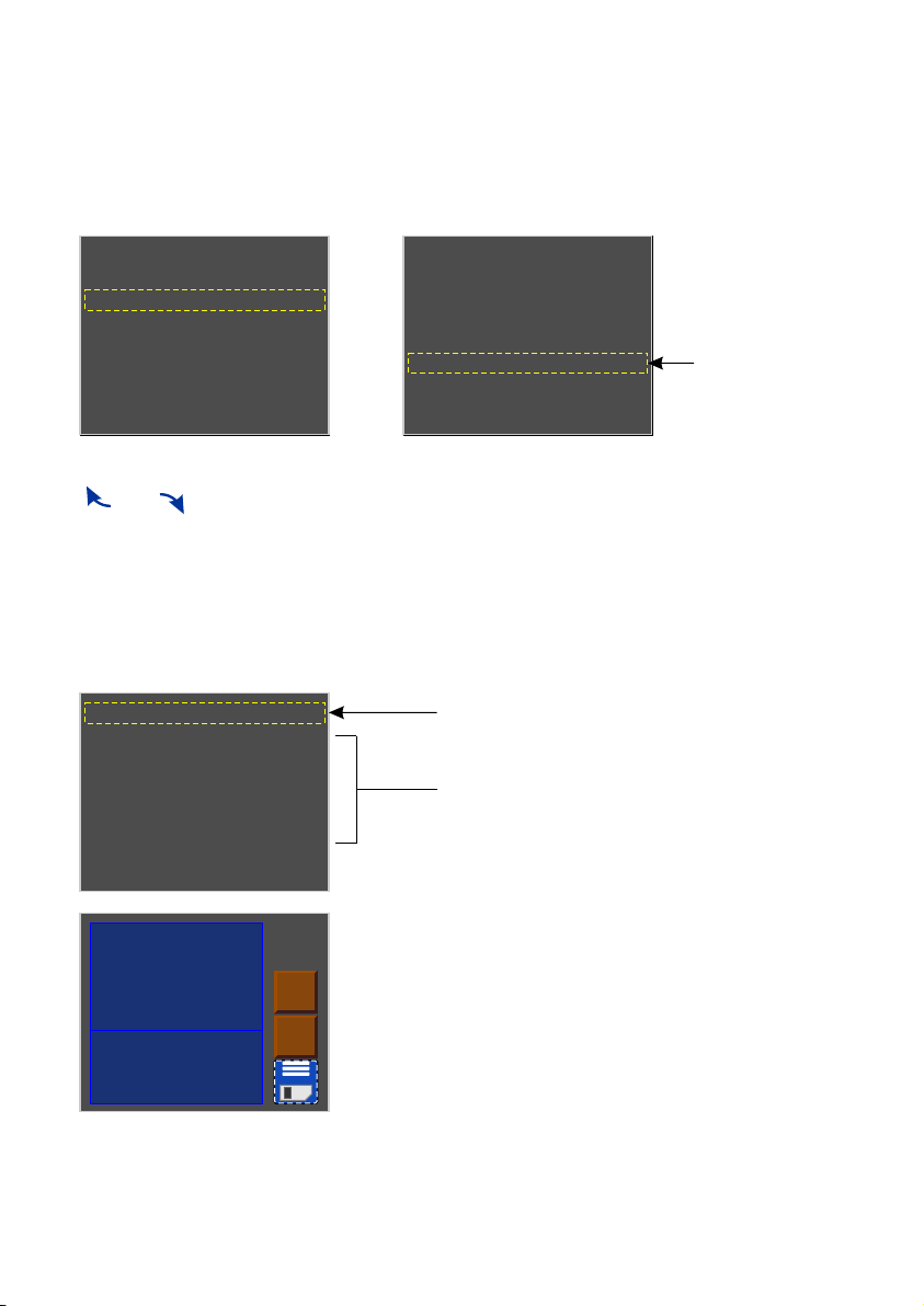
change mode window, after selecting the
selected operating mode, confirm with "enter”
currently set operating mode

6.3. Channel's Balance
9
This option allows you to set control values for each of the six channels operated by the driver.
You can adjust maximum brightness that the diodes can reach in a particular channel and thus set
the range of colours that the lamps controlled will output.
To enable this option, select the [Channel Balance Off] option and confirm your selection by
pressing “enter”. Red colour text will change into green and you will be able to adjust control
values of individual channels. To disable this option, select the [Channel Balance On] option and
confirm your selection by pressing “enter”.
In order to limit values for a particular channel, select a channel and confirm your selection by
pressing “enter” (after which the screen shown below will be displayed) and, using the plus or
minus buttons, set the desired value on the screen.
Ÿ CCW Dyn. - a mode for a lamp fitted with 2x cool diodes and 1x warm diode, with a dimming
feature in the second channel;
Ÿ WWC Dyn. - similarly as above, only for the following colours: 2 x warm white and cool white.
Channel 0 balance = 100%
Channel 1 balance = 027%
Channel 2 balance = 100%
Channel 3 balance = 100%
Channel 4 balance = 046%
Channel 5 balance = 100%
Channel Balance Off
100 –
+
Channel Balance
Settings (0-100)[%]
0% - channel OFF
Channel 0 balance = 100%
Channel 1 balance = 027%
Channel 2 balance = 100%
Channel 3 balance = 100%
Channel 4 balance = 046%
Channel 5 balance = 100%
Channel Balance On

6.4. No DMX Signal
10
8–
+
Scene number
for no DMX signal
Ÿ Program 1 - This option sets one of the 8 available programs which are programmed in the
[Programs Edit] menu when the driver does not detect a DMX signal at the input. In order to
change the number of the program being displayed, follow the same steps as in the preceding
item above.
Ÿ Channels On - If the driver detects a DMX signal loss, the output channels are set to full
brightness.
Ÿ Channels Off - If the driver detects a DMX signal loss, the output channels are disabled, which
in turn, will switch off the lamps.
Scene 1
Program 1
Channels On
Channels Off
RTC Clock
Hold
Master/Slave: Master
List of options available:
Ÿ Scena 1 - This option sets one of the 8 available scenes which are programmed in the [Scenes
Edit] menu when the driver does not detect a DMX signal at the input. To set such a scene in
the menu you need to press “enter” button twice after you select the [Scene 1] option, and a
scene number selection screen will display where you can select an appropriate scene using
the plus or minus buttons.
In this menu, you can configure the response of the device if no DMX signal is received. The
astronomic clock feature is one of the options you can enable. This feature will switch on and off
your lighting system according to sunrise and sunset; you can parametrise sunrise and sunset
time settings, by entering the longitude and latitude values.
In order to set an option available in this menu,
select an option and confirm it by pressing “enter”.

11
In the example shown above, Program 01 will be turned on at sunrise and turned off at sunset.
Ÿ Hold - After this option is selected, when the driver detects loss of DMX signal at the input, it will
continue to hold the last value at the outputs.
Ÿ Master/Slave: Master(Slave) - In this mode, you can determine whether or not, after DMX
signal is lost, the device is operating as a controller. This is the so-called master mode. The
slave mode allows the device only to operate as a DMX transmitter.
Ÿ RTC Clock - The astronomical clock allowing for switching on and off e.g. a particular program,
scene, or lamps according to sunrise and sunset times or times set by the user. To proceed to
program this menu, you need to select the [RTC Clock] option and confirm your selection by
pressing the “enter” button twice. Then the screen shown below will display:
Astronomical Clock
04:34:26
20:53:39
Program
ON OFF
01
–
+–
+
00 –
+
00 –
+
00 –
+
00 –
+
12 –
+
16 –
+
selection of an event that
will be turned on ( ) or off ON
( ) according to the OFF
clock settings
setting sunrise and
sunset times
setting the times at which selected
events are to be turned on ( ) i ON
and off ( )OFF
turn-on time selection field ( ) or turn-off time ON
selection field ( ) for a given time at the level at OFF
which the particular fields are located
Astronomical Clock
04:34:26
20:53:39
Scene
ON OFF
02
–
+–
+
00 –
+
00 –
+
00 –
+
00 –
+
12 –
+
16 –
+
Scene 02 is scheduled to be turned on at
4.00 p.m. and turned off at sunrise.

12
Scene parameters:
[XF] (xfade) - smoothness of fading between programs steps;
[ST] (scene time) - length of the entry of a scene in milliseconds;
[Cont/End] - continuous playback of a program or a scene or termination;
[Ch01:000,..., Ch36:255] - program step values in individual channels.
In order to assign a different input parameter to a DMX output channel, select the one in which you
want to make changes and press “enter”. Next, using the “next” or “previous” buttons set a new
value and confirm it by pressing “enter”.
6.5. Programs Edit
[Program edit] is a menu in which you can set the parameters of subsequent programs and the
scenes (which are subsequent steps of the program) these programs consist of. With this option,
you can set the course of a particular program which the driver can subsequently use when
operating in the no DMX signal mode.
Pr1
Pr2
Pr3
Pr4
Pr5
Pr6
Pr7
Pr8
All
Sc1
Sc2
Sc3
Sc4
Sc5
Sc6
Sc7
Sc8
Sc9
Sc10
XF:50%
ST:5000ms
Cont.
Ch01:255
Ch02:000
Ch03:000
Ch04:255
Ch05:000
Ch06:000
Ch07:000
selection of a single program
(or simultaneously all of the
programs [All]) for editing
selection of one of 20 scenes (or simultaneously
all of the scenes [All]) for editing
editing the parameters of individual scenes of the
program that is selected in the first column

6.6. Scenes Edit
6.7. Temperature limits
13
The [Temperature limits] option allows you to set a temperature limit which, if reached, triggers
power reduction or causes the device powered by the driver to be turned off. The temperature
sensor is installed inside the PX178.
In the [Scene edit] menu you can change settings for individual scenes. A programmed scene is
played back continuously. The meanings of particular messages are described in the previous
section (6.5. Program edit).
The graph below shows how this feature operates:
Output
power
Temperature
0Sensor On
default: 50°C
Sensor Off
default: 90°C
100%
Sc1
Sc2
Sc3
Sc4
Sc5
Sc6
Sc7
Sc8
Sc9
Sc10
XF:50%
ST:5000ms
Ch01:255
Ch02:000
Ch03:000
Ch04:255
Ch05:000
Ch06:000
Ch07:000
Ch08:255
selection of one of 20 scenes (or simultaneously
all of the scenes [All]) for editing
editing individual scenes of the program
that is selected in the first column

6.8. Clock and date
14
80 –
+
Minimal temperature
of sensor to limit
power of channel
[°C]
Temperature limitation
90 °C
Sensor 1 On
50 °C
Sensor 1 Off
29.1°C
100%
This menu allows you to change dates and times saved in the driver. Changes are made using the
plus and minus buttons.
brightness reduction trigger temperature (set within
the range of 20÷70°C)
temperature at which brightness is totally reduced
(e.g. lamps are turned off) - set within the range of
20÷90°C
current temperature and power output level
12 28 12
2017 07 07
+
+
+
++
+
–––
–
–
–
time [hour:minute:second]
date [year:month:day]

6.9. Screensaver
6.10. Local settings
15
This driver has a feature allowing you to turn off the screen backlight. In the [Screensaver] menu,
you can enable this mode after a pre-set idle time (i.e. not pressing programming buttons on the
driver). To set the screensaver, confirm by pressing the “enter” button [Screensaver OFF] and
then set the time period after which the screen backlight will be turned off. To do this, select the
[Set] button and confirm by pressing “enter”. A new screen will display where you can set
screensaver parameters.
The local settings are responsible for setting the location of your PX178 device according to
geographical coordinates (longitude and latitude), and for setting the time zone in which the
device operates.
15 –
+
Screensaver Time
[s]
Set
15[s]
Screensaver OFF
turning on/off the screensaver
changing the time period after which the screen
backlight is turned off
GMT+1
Time zone
+–
20°05'E
Longitude
+–
50°04' E
Latitude
+–

6.11. PWM frequency
6.12. DMX Out Settings
16
After you select the [DMX Output Settings] menu, the screen displays the current settings for
DMX signal parameters. This menu allows you to modify the parameters of the DMX512 signal
being transmitted by the driver operating in the master mode. The values shown below are the
default settings for the device:
At the bottom of the screen, aggregate [Packet length] and [ ] are displayed for the Refresh rate
parameters thus configured.
[PWM frequency] - This allows you to change the LED refresh rate from 287 Hz to 1082 Hz.
Changing to a higher frequency enables the "flicker free" mode. This feature is very useful for the
purpose of controlling lamps in television studios. It allows the user to prevent unpleasant flicker
effect that is due to inadequate synchronisation of the LED control signal.
Frequency 1098Hz
Frequency 274Hz the current frequency setting is highlighted in
blue; to change the frequency, use the arrows
to move the outline rectangle and confirm by
pressing the “enter” button.
Break Time[μs]
120
MAB Time[μs]
60
MBF[μs]
0
Packet gap[μs]
100
Channels number
512
Packet length: 22808[μs]
Refresh rate: 43[Hz]

17
BREAK BREAK
MAB
M
B
F
M
B
F
M
B
F
M
B
F
M
B
F
START
CODE
DIMMER
1
DIMMER
2
DIMMER
3
DIMMER
511
DIMMER
512
full DMX package
1. Break Time - option allowing you to modify the intervals between subsequent DMX packets.
As many devices available on the market have no compliance with
the DMX512 standard, the following options allow for selecting
appropriate parameters of the output signal to a given device.
If there are any problems, it is recommended to use longer
Break Length, MAB, Channel break and package.
+
120 –
Break Length Time
Minimum 88[μs] relevant information that helps you to set the
proper value
2. MAB Time (Mark after break) – this is the time interval after Break that is present in each packet
according to the DMX512 standard. You should set this parameter at a value within the
range of 8 - 1000 μs.
3. MBF (Mark Between Frames) – Interval between DMX512 frames (channels). Its length may
vary from 0 to 1 second; the shorter the interval, the better. MBFs separate stop bits of one
channel from the start bits of another channel.
4. Packet gap – Interval between packets from the last slot to the Break start (Mark after last
channel). The PX178 allows for setting this parameter within the range of 16 - 5000 μs.
5. Channels number – This feature allows you to reduce the number of channels being sent by
the PX178. The minimum value is 24 channels, and maximum is 512 (default value).

6.13. Input DMX
6.14. Internal smooth
18
DMX signal presentation:
The value of DMX signal in a particular DMX channel is presented as a white bar whose height
varies in proportion to the following relationship: the greatest height = DMX signal value is 255; no
bar = DMX signal value is 0.
The [Input DMX] menu is a graphical view of the DMX512 signal that is being received by the
driver. The right-hand side picture shows the screen displayed when no DMX signal is being
received by PX 178:
Frame
+1
+129
+257
+385
Frame
+1
+129
+257
+385
Brak syg. DMX
DMX signal value in a
particular DMX channel
subsequent ten channels
channel numbers
The transition smoothing option, intended for transitions between successive control signal
values, allows you to make smooth transitions between e.g. colours in the lamps connected.
This menu allows for setting the smoothing feature in two versions:
[Smooth Disabled] - the smoothing feature operates in a linear way between subsequent DMX
signal packets being received by the driver
[Packet To Packet Smooth] - this feature allows you to apply a time criterion for smoothing DMX
signal received by the driver. Once you confirm the message using the “enter” button, you can
select a time setting within the range of 10 - 400 ms. This time setting determines the distance
between DMX signal values that have been smoothed linearly.
[Time Smooth] - if this option is enabled, the smoothing feature is disabled

The language settings allow you to change the menu language. To do this, select the appropriate
language icon and confirm your selection by pressing “enter”.
6.15. Language
6.16. Firmware info
In this submenu, you can check the firmware and bootloader version installed on your PX178
driver. You can also restore the default settings implemented on the device.
Set default settings
Firmware version
02.07
Bootloader version
Px178Bootv02.01
Yes No
S/N: 17120020
software version information
device serial number
select this to go the default setting restore
option (confirm by pressing the “enter” button)
Set default settings
Firmware version
02.07
Bootloader version
Px178Bootv02.01
Yes No to restore the default settings, use the arrows
to select [Yes] button and confirm with “enter”
19

7. CONNECTION SCHEME
20
power supply
12-24 V DC
LN
DC OK
LED strip group
B
G
R
+
LED strip group
B
G
R
+
LED strip group
B
G
R
+
LED strip group
B
G
R
+
DMX controller
e.g PX333
PX178
LED Driver
6x7,5A
a) Connection between LED strip group and a common power supply
Other manuals for PX178
1
Table of contents
Other PXM Lighting Equipment manuals
Popular Lighting Equipment manuals by other brands

Federal Signal Corporation
Federal Signal Corporation Electraray 225 instruction manual

Jandy
Jandy Levolor K-1100 installation instructions

Inivos
Inivos ULTRA-V User instruction manual

Iluminarc
Iluminarc Ilumipod 18g2 IP Optic RGB user manual

Eaton
Eaton FlexiTech AT L Series manual

TRADINGZONE
TRADINGZONE Stehlampe Free MPP-SEN installation manual