PXM Rail DMX Merger User manual

Manual
Rail DMX
Merger
PX173
R

CONTENTS
1. General description.............................................................................
2. Safety conditions................................................................................
3. Rules of creating a DMX installation..................................................
4. View of the front panel........................................................................
4.1. Button features...................................................................
5. Programming......................................................................................
6. DMX signal connection characteristics...............................................
7. Connection ............................................................................
8. Technical specification........................................................................
9. Declaration of conformity...................................................................
scheme
1
1
2
3
3
3
4
6
6
7
Manufacturer reserves the right to make modifications in order to improve device operation.
PXM s.c.
ul. Przemysłowa 12
30-701 Kraków, Poland
tel.: (+48 12) 626 46 92
fax: (+48 12) 626 46 94
E-mail: [email protected]
Internet: www.pxm.pl

1. GENERAL DESCRIPTION
1
The DMX-512 standard is a protocol that defines the serial control data transmission for 512
channels. Many of the produced controllers does not use the full packet of 512 addresses and
sends out the data for a lesser number of channels. In some installations, where a few of such
controllers operate, there is a need to "sum up" the outputs of the particular devices and send
them out through the single DMX route.
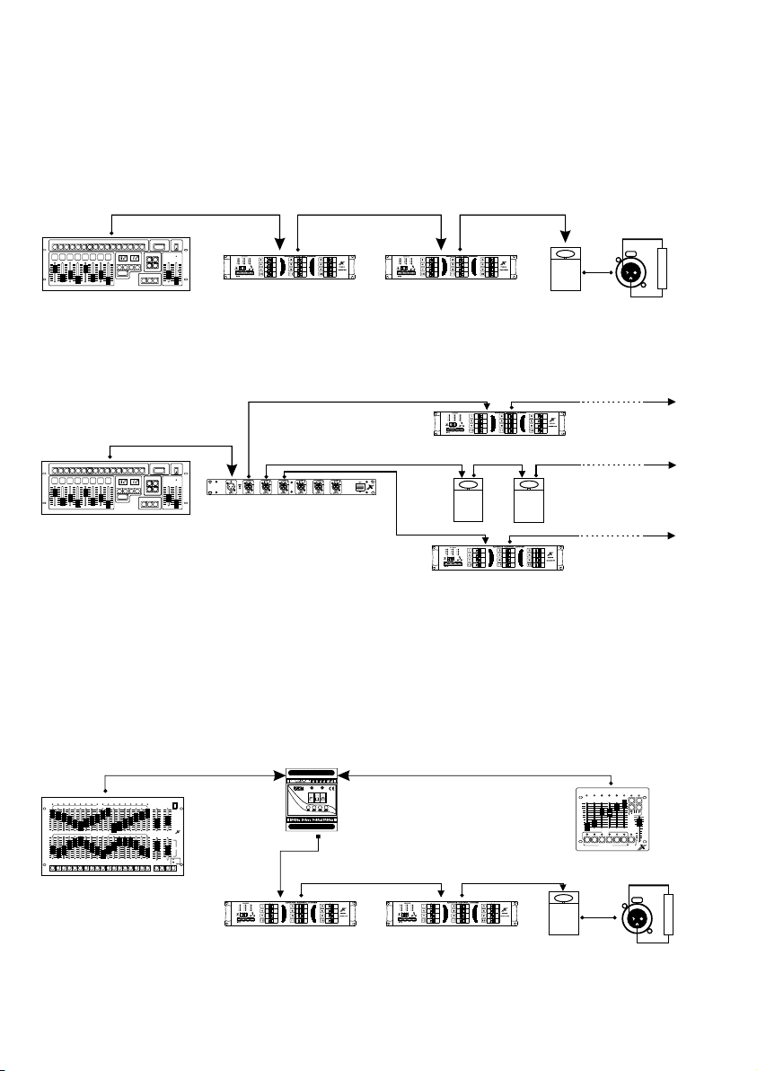
DMX Merger is a device that allows to add up the DMX signals - receive the data from a few
inputs, arrange them in a proper order and send them into a single 512-channels output.
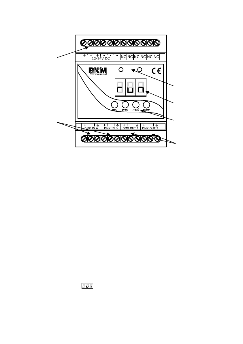
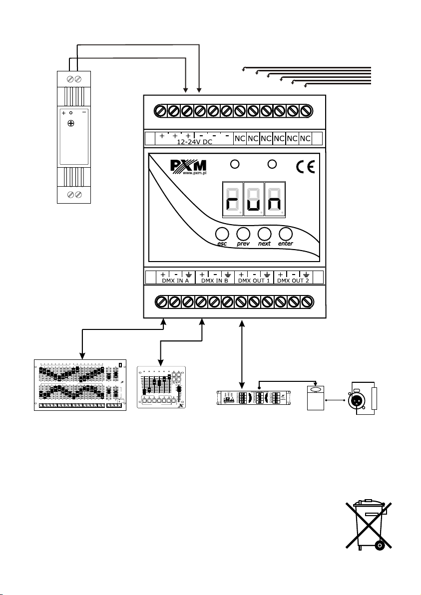
PX173 DMX Merger is an adder of two 512-channels inputs. The device installation is
confined to power supply connection and pinning the DMX control cables (with the standard 3-pin
XLR-3 plugs and sockets). The facilities of the DMX installation control and maintenance are the
LED indicators of the DMX signal presence in the particular input routes ("A" and "B") and the
built-in special control system with the operation mode display, that allows to control entirely the
receivers in the DMX route. The receivers must be connected in series forming the chain, on the
output of the last device the terminator (110 Ohm resistor) must be installed.
2. SAFETY CONDITIONS
PX173 DMX Merger is powered with safe voltage 12-24V; however, during its installation and
use the following rules must be strictly observed:
1. The device may only be connected to 12-24V DC current (stabilized voltage) with current-
carrying capacity compatible with technical data.
2. Installation of the device have to be performed in accordance to description in this manual.
3. All the conductors should be protected against mechanical and thermal damage.
4. In the event of any conductor damaging, it should be replaced with the one of the same
technical specification.
5. Connection of DMX signal should be made with shielded conductor.
6. All repairs and connections of outputs or DMX signal can only be made with power off.
7. PX173 should be strictly protected against contact with water and other liquids.
8. All sudden shocks - particularly dropping - should be avoided.
9. The device cannot be turned on in places with humidity exceeding 90%.
10. The device cannot be used in places with temperature lower than +2°C or higher than
+40°C.
11. For cleaning use only a damp cloth.

3. RULES OF CREATING DMX INSTALLATION
2
PUSH PUSH PUSH PUSH
PUSH
PUSH
DMX
splitter
PX094
BLACKOUT POWER
1 2 3 4 5 6 7 8 9 10 14
13
11 12 15 16
SCANNER
LOAD PROGRAM
PROGRAM
-
+
SCENE
-
+
MIDI
MUSIC AUTO
TRIGGERING
SAVE
MIDI
END
PROGRAMMING
SPEED
X FADE SPEED
AUTO CONTROL
PX 111
Mirage SE
Scanner
Scanner
Mirage control desk DMX Splitter
Dimmpack 12 x 2300 W
IN
IN
IN
IN
IN
OUT
OUT
OUT
OUT
OUT
OUT
OUT
OUT
0
Terminator
Scanner
Opera control
Club 6p control desk
DMX Merger
Dimmpack 12 x 2300 W Dimmpack 12 x 2300 W DMX OUT
Opera
10 11 12 13 14 15 16 17 181 2 3 4 5 6 7 8 9
CHASER
SPEED
B
PRESET
10 11 12 13 14 15 16 17 181 2 3 4 5 6 7 8 9
PRESET A
MUSIC
SAVE
SCENE
SAVE
CHASER
PRESET
MEMORY
A
AUX MASTER
I
O
PRESET B / MEMORY
IN
IN IN IN
IN
OUT
OUT
OUT
OUT OUT
Chaser Select
Flash
Memory
1 2 3 4 5 6
PX015
1 2 3 4 5 6 Chaser Scene
Club 6p
90
% 100
80
70
60
50
40
30
20
10
0
100 %
90
80
70
60
50
40
30
20
10
0
Master
MusicSpeed
1
2
3
PUSH
RESISTOR
110 Ohm
BLACKOUT POWER
1 2 3 4 5 6 7 8 9 10 14
13
11 12 15 16
SCANNER
LOAD PROGRAM
PROGRAM
-
+
SCENE
-
+
MIDI
MUSIC AUTO
TRIGGERING
SAVE
MIDI
END
PROGRAMMING
SPEED
X FADE SPEED
AUTO CONTROL
PX 111
Mirage SE
Scanner
Mirage control desk Dimmpack 12 x 2300 W Dimmpack 12 x 2300 W DMX OUT
IN IN IN
OUT OUT OUT
0
Terminator
1
2
3
PUSH
RESISTOR
110 Ohm
PX173
DMX Merger
DMX A DMX B
DMX-512 is a typical installation in series. That is why all the receiving devices (effects) are
always equipped with two sockets for DMX connection: one input socket ("IN") and one output
socket ("OUT"). The signal from the controller gets to the first device and then, from its output, to
the second, etc. At the end of a line created in such way the terminator must be installed (see the
illustration below).
There are some situations, when the DMX line must be splitted (eg. to save on the cables). In
such case you need to apply a device called DMX Splitter.
Sometimes you are faced with the opposite situation: two DMX signals going out from different
controllers through the independent lines need to be summed up and sent further through one,
common line. The typical example is the theatre, where the main console is used for lighting
control during the performance. During the day this console is off and inaccessible. That is why
the second, smaller console can be placed near the scene. Both these consoles control the same
lights. In such case the DMX line adder, that is DMX Merger, must be applied.
Apart from two-lines summing, the Merger popularises the wide range of possibilities of defining
the dependances between inputs. For the precise description see the further part of the manual.

4. VIEW OF THE FRONT PANEL
3
ENTER
CANCEL
NEXT
PREV
- enters the next MENU level and confirms changes made,
- goes back to the previous MENU level or discards changes made,
- scrolls to the next feature on the same MENU level or increases the parameter's
value,
- scrolls to the previous feature on the same MENU level or decreases the
parameter's value
4.1. BUTTON FEATURES
5. PROGRAMMING
The point of merger programming is to define a number of DMX addresses and the number of
data in the input lines, and determining the dependences that occur between them.
In a basic operation mode the inscription is displayed.
To enter the programming mode, press the ENTER key.
DMX-512
Outputs
Display
Control
buttons
Power supply
DMX-512
Inputs
DMX signal
control diodes
PX173
DMX Merger
DMX A DMX B

ENTER
ENTER
NEXT
NEXT
NEXT
NEXT
NEXT
NEXT
NEXT
NEXT
ENTER
NEXT
NEXT
4
100 %
100 %
100 %
1
DMX channels
2 3 4 5 6 7
. . . . . . 512
0
0
0
Input A
Output
Input B
6. DMX SIGNAL CONNECTION CHARAKTERISTICS
MERGER
(połączenie)
DMX “A” devicesignal of
DMX signal of “B” device
Output DMX signal
The example of summing up of 2 channels with the comparison feature .
Merger basic operation mode.
Output 1 programming.
Number of the first summed channel of the A input.
Number of the summed channels from the A input.
Number of channel on the output 1, where the first (selected in )
channel is going to get.
Number of the first summed channel of the B input.
Number of the summed channels from the B input.
Number of channel on the output 1, where the first (selected in )
channel is going to get.
Mode of execution of the dependences between the corresponding
channels.
After comparison of the inputs value for each channel separately,
the greater value is sent to the output.
After comparison of the inputs value for each channel separately,
the smaller value is sent to the output.

Output 2 programming.
...further programming mode as in output 1.
NEXT
NEXT
NEXT
NEXT
NEXT
NEXT
NEXT
NEXT
NEXT
NEXT
NEXT
CANCEL
CANCEL
ENTER
5
After comparison of the inputs value for each channel separately,
the subtraction result value is sent to the output.
The B input is sent to the output as long, as the DMX transmission
is absent on the A input. When the signal appears on the A input, it
is sent to the output and the B input is ignored.
The A input is sent to the output as long, as the DMX transmission
is absent on the B input. When the signal appears on the B input, it
is sent to the output and the A input is ignored.
The B input is sent to the output as long, as the DMX transmission
on the A input equals the value of the channel from the B input.
When the signals are equal, the signal from the A input it is sent to
the output and the B input is ignored.
The A input is sent to the output as long, as the DMX transmission
on the B input equals the value of the channel from the A input.
When the signals are equal, the signal from the B input it is sent to
the output and the A input is ignored.
The A input is sent to the output only. The B input is ignored.
Regardless of both inputs, zero values are sent to the output.
Regardless of both inputs, all declared output channels are
controlled at 100%.
Defines the number of channels sent to the output. According to the
DMX standard, this number must fit in the range from 24 to 512.

6
8. TECHNICAL SPECIFICATION
terminal blocks
terminal blocks
12 - 24 V DC
max. 4 W
70 mm
86 mm
60 mm
- DMX input
- DMX output
- Power supply
- Current consumption
- Dimensions:
- width
- height
- depth
power supply
12-24 V DC
NOT CONNECTED
PX173
DMX Merger
DMX A DMX B
LN
DC OK
7. CONNECTION SCHEME
np. DR-15-12
Opera control desk
Opera
10 11 12 13 14 15 16 17 181 2 3 4 5 6 7 8 9
CHASER
SPEED
B
PRESET
10 11 12 13 14 15 16 17 181 2 3 4 5 6 7 8 9
PRESET A
MUSIC
SAVE
SCENE
SAVE
CHASER
PRESET
MEMORY
A
AUX MASTER
I
O
PRESET B / MEMORY
Chaser Select
Flash
Memory
1 2 3 4 5 6
PX015
1 2 3 4 5 6 Chaser Scene
Club 6p
90
% 100
80
70
60
50
40
30
20
10
0
100 %
90
80
70
60
50
40
30
20
10
0
Master
MusicSpeed
Dimmpack 12 x 2300 W DMX OUT
1
2
3
PUSH
110 Ohm
Club 6p control Scanner

PXM s.c.
ul. Przemysłowa 12
30-701 Kraków, Poland
Rail DMX Merger
PX173
PN-EN 55103-1
PN-EN 55103-2
DMX signal connection must be made with
a shielded cable, connected to pin GND.
Marek Żupnik M.Sc., Eng.
Name of producer:
Address of producer:
declares that the product:
Name of product:
Type:
answers the following product specifications:
Additional informations:
Kraków, 20.04.2010
7
DECLARATION OF CONFORMITY
according to guide lines 2004/108/WE
stage and theatre consoles digital dimmers dmx systems architectural lighting controllers led lighting
tel: +48 12 626 46 92
fax: +48 12 626 46 94
e-mail: [email protected]
http://www.pxm.pl
ul. Przemysłowa 12
30-701 Kraków, Poland
This manual suits for next models
1
Table of contents
Other PXM Lighting Equipment manuals
Popular Lighting Equipment manuals by other brands

Monzana
Monzana DBLK001 instructions

Larson Electronics
Larson Electronics HAL-MB-185LED-CPR-100 instruction manual

Welch Allyn
Welch Allyn Solarc M21P011 Technical operation guide

Velleman
Velleman HQ POWER VDLNS8 manual

JUST NORMLICHT
JUST NORMLICHT DLS COLOR VIEWING LIGHT V7 L Assembly and instruction manual

iGuzzini
iGuzzini Sirolo manual