Pyramid Technical Consultants I128 User manual

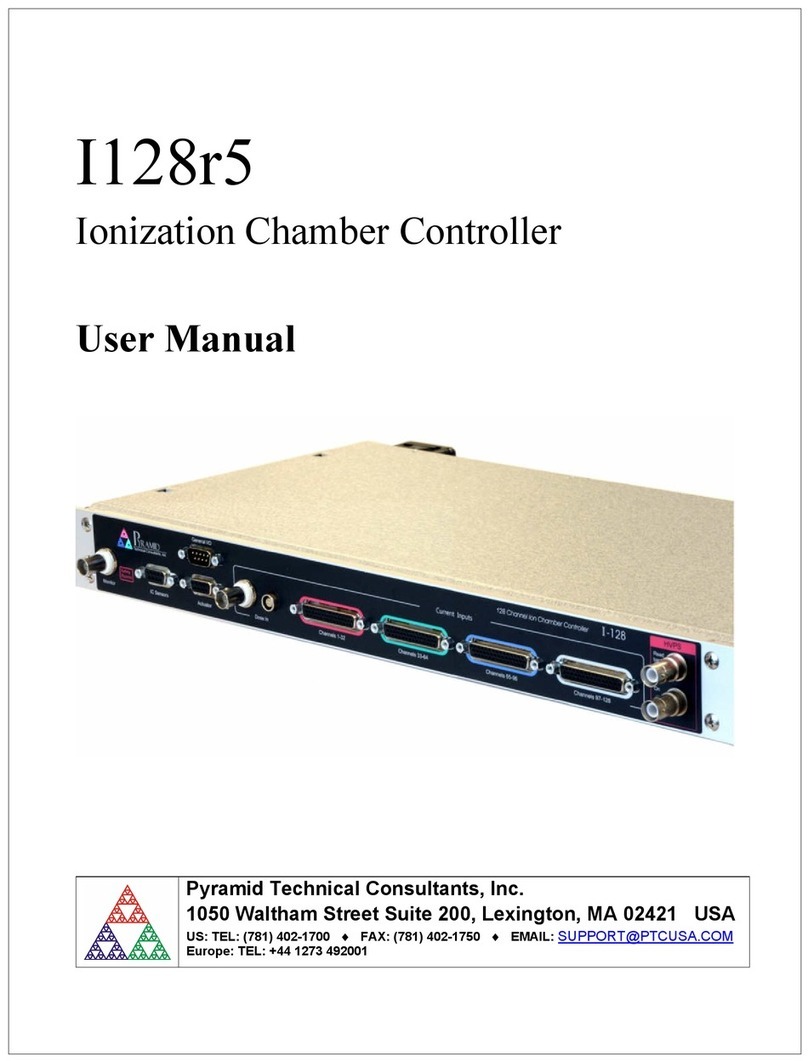
I128
Ionization Chamber Controller
User Manual
Pyramid Technical Consultants, Inc.
1050 Waltham Street Suite 200, Lexington, MA 02421 USA
US: TEL: (781) 402-1700 FAX: (781) 402-1750 EMAIL: SUPPORT@PTCUSA.COM
Europe: TEL: +44 1273 492001

I128 User Manual
PTC2-2120709629-4038 Version: 2.0 Page 2 of 127
1 Contents
1 CONTENTS ........................................................................................................................................................ 2
2 FIGURES ............................................................................................................................................................ 6
3 SAFETY INFORMATION ............................................................................................................................... 8
4 MODELS .......................................................................................................................................................... 10
5 SCOPE OF SUPPLY ....................................................................................................................................... 11
6 OPTIONAL ITEMS AND RELATED PRODUCTS .................................................................................... 12
6.1 IONIZATION CHAMBERS .................................................................................................................................. 12
6.2 POWER SUPPLIES ............................................................................................................................................ 12
6.3 SIGNAL CABLES AND CABLE ACCESSORIES ..................................................................................................... 12
6.4 DATA CABLES ................................................................................................................................................ 12
6.5 TRIGGER DISTRIBUTION ................................................................................................................................. 13
7 INTENDED USE AND KEY FEATURES .................................................................................................... 14
7.1 INTENDED USE ............................................................................................................................................... 14
7.2 KEY FEATURES .............................................................................................................................................. 14
8 SPECIFICATION ............................................................................................................................................ 16
9 INSTALLATION ............................................................................................................................................. 23
9.1 MOUNTING ..................................................................................................................................................... 23
9.2 GROUNDING AND POWER SUPPLY ................................................................................................................... 23
9.3 CONNECTION TO SIGNAL SOURCE ................................................................................................................... 24
Typical setup ........................................................................................................................................ 24
Cables .................................................................................................................................................. 27
Signal current path .............................................................................................................................. 27
10 HOW THE I128 WORKS AND HOW TO USE IT - AN OVERVIEW ..................................................... 30
10.1 MULTICHANNEL ELECTROMETER INPUT (CHANNELS 1 TO 128) ................................................................. 30
10.2 INTEGRAL PLANE ELECTROMETER INPUT (CHANNEL 0 - HCC) .................................................................. 31
10.3 ACQUISITION MODES ................................................................................................................................. 32
10.4 TRIGGERING .............................................................................................................................................. 32
10.5 SELF-TESTING AND CALIBRATION.............................................................................................................. 32
10.6 HIGH VOLTAGE OUTPUT ............................................................................................................................ 33
10.7 GENERAL-PURPOSE I/O (IONIZATION CHAMBER SERVICES) ....................................................................... 33
10.8 GENERAL-PURPOSE I/O (ACTUATOR CONTROL) ......................................................................................... 33
10.9 MAP EXECUTION AND INTERLOCKING ....................................................................................................... 34
10.10 CONTROLLING REMOTE DEVICES – FIBER OPTIC INTERFACES .................................................................... 34
10.11 MONITOR UNIT OUTPUT ............................................................................................................................. 35
10.12 COMMUNICATION TO THE HOST COMPUTER ............................................................................................... 35
10.13 EMBEDDED SOFTWARE .............................................................................................................................. 35
11 GETTING STARTED USING THE PTC DIAGNOSTIC G2 HOST PROGRAM ................................... 36
11.1 INSTALLATION........................................................................................................................................... 36
11.2 CONNECTING TO THE I128 ......................................................................................................................... 37

I128 User Manual
PTC2-2120709629-4038 Version: 2.0 Page 3 of 127
11.3 SCREEN LAYOUT – TOP BANNER ................................................................................................................ 41
11.4 SCREEN LAYOUT – RIGHT-HAND TABS ...................................................................................................... 42
Data tab .......................................................................................................................................... 42
Data analysis .................................................................................................................................. 44
Device ............................................................................................................................................. 45
Setup ................................................................................................................................................ 50
Calibration ...................................................................................................................................... 52
Real Time Processing ...................................................................................................................... 54
Interlocks......................................................................................................................................... 54
Properties ........................................................................................................................................ 55
11.5 SCREEN LAYOUT - GRAPHIC DISPLAY ........................................................................................................ 56
Strip display .................................................................................................................................... 57
Scope display .................................................................................................................................. 58
Histogram display ........................................................................................................................... 58
Cursor ............................................................................................................................................. 58
Filtering and zero subtraction ........................................................................................................ 59
11.6 DATA LOGGING ......................................................................................................................................... 61
12 I128 CIRCUIT OVERVIEW .......................................................................................................................... 62
12.1 PHYSICAL CONFIGURATION ....................................................................................................................... 62
12.2 FUNCTIONS ................................................................................................................................................ 62
Signal current inputs ....................................................................................................................... 62
Calibration current switching ......................................................................................................... 64
Analog signals ................................................................................................................................. 64
Digital signals ................................................................................................................................. 64
High voltage .................................................................................................................................... 65
Interlocks......................................................................................................................................... 65
A60 .................................................................................................................................................. 65
Secondary FPGA............................................................................................................................. 65
Power supplies ................................................................................................................................ 66
13 HIGH VOLTAGE SUPPLIES ........................................................................................................................ 67
13.1 SETTING THE HIGH VOLTAGE SUPPLIES .................................................................................................... 67
13.2 CHANGING THE HIGH VOLTAGE SUPPLY RANGE AND POLARITY .............................................................. 68
14 SAMPLES, LOGGED DATA, INTEGRATION AND AVERAGING ....................................................... 69
14.1 READINGS AND LOGGED DATA .................................................................................................................. 69
14.2 INTEGRATION TIME .................................................................................................................................... 69
14.3 CONVERSIONS PER SAMPLE ....................................................................................................................... 70
14.4 GENERAL PURPOSE ANALOG INPUTS .......................................................................................................... 71
15 TRIGGERS AND DATA BUFFERING ........................................................................................................ 72
15.1 INTERNAL TRIGGER MODE ......................................................................................................................... 72
15.2 DATA BUFFERS .......................................................................................................................................... 72
I128 internal buffer ......................................................................................................................... 72
PTC DiagnosticG2 buffer ............................................................................................................... 73
15.3 EXTERNAL TRIGGERING ............................................................................................................................ 73
Custom triggering ........................................................................................................................... 73
Pre-defined trigger modes .............................................................................................................. 76
Trigger response time ..................................................................................................................... 77
16 MONITOR PULSE OUTPUT ........................................................................................................................ 78
17 ACTUATOR CONTROL ................................................................................................................................ 79
18 INTERLOCKS AND DIRECT CONTROL LINES ..................................................................................... 80

I128 User Manual
PTC2-2120709629-4038 Version: 2.0 Page 4 of 127
18.1 PROCESS CONTROL OUTPUTS ..................................................................................................................... 80
18.2 INTERLOCKS .............................................................................................................................................. 80
Enable/Status .................................................................................................................................. 81
Interlock .......................................................................................................................................... 82
Relay ............................................................................................................................................... 82
19 CONNECTING SLAVE DEVICES ............................................................................................................... 83
20 CALIBRATION ............................................................................................................................................... 84
20.1 CURRENT CALIBRATION ............................................................................................................................ 84
20.2 OTHER CALIBRATIONS ............................................................................................................................... 84
21 PEAK FITTING ............................................................................................................................................... 85
22 USING THE TRIANGLE GENERATOR TEST BOARD .......................................................................... 87
23 GATE CONNECTIONS .................................................................................................................................. 89
24 CONNECTORS ............................................................................................................................................... 90
24.1 FRONT PANEL CONNECTORS ...................................................................................................................... 90
I/O port (environmental monitors) .................................................................................................. 90
Actuator .......................................................................................................................................... 91
HCC: High current input (channel 0) ............................................................................................. 91
Signal inputs (strip inputs) .............................................................................................................. 92
High voltage output and input......................................................................................................... 94
24.2 REAR PANEL CONNECTORS ........................................................................................................................ 94
Ethernet communications ................................................................................................................ 94
RS-232 / RS-485 communications ................................................................................................... 94
Gate input and output ..................................................................................................................... 95
Monitor input .................................................................................................................................. 95
Fiber-optic communications ........................................................................................................... 95
Enable/Status port ........................................................................................................................... 95
Interlock port .................................................................................................................................. 96
Relay port ........................................................................................................................................ 96
Power input, 24 VDC ...................................................................................................................... 96
Ground lug ...................................................................................................................................... 96
25 CONTROLS AND INDICATORS ................................................................................................................. 97
25.1 FRONT PANEL CONTROLS .......................................................................................................................... 97
Key switch ....................................................................................................................................... 97
25.2 REAR PANEL CONTROLS ............................................................................................................................ 97
Address switch ................................................................................................................................ 97
Mode switch .................................................................................................................................... 97
Reset button ..................................................................................................................................... 97
25.3 FRONT PANEL INDICATORS ........................................................................................................................ 98
Power on ......................................................................................................................................... 98
Mode switch .................................................................................................................................... 98
HV on .............................................................................................................................................. 98
25.4 REAR PANEL INDICATORS .......................................................................................................................... 98
Power .............................................................................................................................................. 98
Initiated ........................................................................................................................................... 98
Active .............................................................................................................................................. 98
Com ................................................................................................................................................. 98
Power up LED sequence ................................................................................................................. 98
RJ-45 indicators .............................................................................................................................. 99

I128 User Manual
PTC2-2120709629-4038 Version: 2.0 Page 5 of 127
26 COMMUNICATIONS INTERFACES ........................................................................................................ 100
26.1 ETHERNET ............................................................................................................................................... 100
26.2 WEB SERVER ........................................................................................................................................... 100
26.3 RS-232 CONNECTION .............................................................................................................................. 101
26.4 RS-485 CONNECTION EXAMPLE ............................................................................................................... 102
26.5 FIBER OPTICS ........................................................................................................................................... 102
27 USING THE I128 ON A NETWORK .......................................................................................................... 104
27.1 NETWORK CONFIGURATIONS ................................................................................................................... 104
27.2 RECOVERY FROM UNKNOWN IP ADDRESS ............................................................................................... 105
Reset at boot time .......................................................................................................................... 105
Using the serial port ..................................................................................................................... 106
27.3 SYSTEM LOG ADDRESS ............................................................................................................................ 106
28 ASCII COMMUNICATION ......................................................................................................................... 107
28.1 USING PUTTY TO TEST THE SERIAL ASCII CONNECTION ........................................................................ 107
29 CREATING A HOST SOFTWARE APPLICATION ................................................................................ 108
30 FAULT-FINDING ......................................................................................................................................... 115
31 MAINTENANCE ........................................................................................................................................... 121
31.1 COOLING FAN MAINTENANCE .................................................................................................................. 121
31.2 CALIBRATION .......................................................................................................................................... 122
32 RETURNS PROCEDURE ............................................................................................................................ 123
33 SUPPORT ....................................................................................................................................................... 124
34 DISPOSAL ...................................................................................................................................................... 125
35 DECLARATION OF CONFORMITY ........................................................................................................ 126
36 REVISION HISTORY................................................................................................................................... 127

I128 User Manual
PTC2-2120709629-4038 Version: 2.0 Page 6 of 127
2 Figures
Figure 1. Serial adaptor cable .................................................................................................................................. 12
Figure 2. I128 front and rear panels. Dimensions mm. ....................................................................................... 21
Figure 3. I128 case plan and side views. Dimensions mm. ................................................................................... 22
Figure 4. Schematic example: basic I128 installation ............................................................................................ 25
Figure 5. Schematic example: I128 installation for dual IC128-25 ionization chambers ................................... 26
Figure 6. Current return path: ionization chamber bias provided by HV module in the I128 ......................... 28
Figure 7. Current return path: ionization chamber bias provided separate HV module .................................. 29
Figure 8. Multichannel electrometer input (one of 128 identical parallel inputs, ch1 to 128) ........................... 30
Figure 9. HCC (integral plane, ch0) electrometer input ....................................................................................... 31
Figure 10. High voltage loopback arrangement ..................................................................................................... 33
Figure 11. Schematic example: I128 control of remote devices ............................................................................ 34
Figure 12. PTC DiagnosticG2 installation .............................................................................................................. 37
Figure 13. Direct Ethernet connection. ................................................................................................................... 38
Figure 14. Configuring the IP address on the host computer. .............................................................................. 38
Figure 15. Ping test of the Ethernet connection. .................................................................................................... 39
Figure 16. Discover devices in progress .................................................................................................................. 40
Figure 17. Ready to connect to the I128 .................................................................................................................. 40
Figure 18. Opening the I128 window ...................................................................................................................... 41
Figure 19. HCC graphic displayed .......................................................................................................................... 43
Figure 20. Data analysis display – I128 and PTC DiagnosticG2 calculations ..................................................... 44
Figure 21. IC Device Support ................................................................................................................................... 45
Figure 22. Pixelated device setup screen .................................................................................................................. 47
Figure 23. Measured parameters from pixelated data ........................................................................................... 47
Figure 24. Pixelated Display Options ....................................................................................................................... 48
Figure 25. MLFC setup ............................................................................................................................................. 49
Figure 26. MLFC Energy Display ............................................................................................................................ 50
Figure 27. Setup - Measuring sub-tab ................................................................................................................... 50
Figure 28. Setup - Trigger sub-tab ........................................................................................................................ 51
Figure 29. Setup - HCC sub-tab ............................................................................................................................ 52
Figure 30. Calibration source control ..................................................................................................................... 53
Figure 31. Current input calibrations ..................................................................................................................... 53
Figure 32. Interlock test functions ........................................................................................................................... 54
Figure 33. Firmware versions .................................................................................................................................. 55
Figure 34. Communication settings ......................................................................................................................... 56
Figure 35. IP Configuration control ........................................................................................................................ 56
Figure 36. Graphics display with HCC display enabled. ...................................................................................... 57
Figure 37. Scope mode capture of a pulse............................................................................................................... 58
Figure 38. Strip chart data display showing cursor. .............................................................................................. 59
Figure 39. Increasing the low pass filtering of the displayed data. ....................................................................... 60
Figure 40. Zero correction of displayed data ......................................................................................................... 61
Figure 41. I128 physical layout. ............................................................................................................................... 62
Figure 42. I128 block schematic. ............................................................................................................................. 64
Figure 43. High voltage jumper settings ................................................................................................................. 68
Figure 44. Data feed into samples............................................................................................................................ 70
Figure 45. Contiguous data number of samples as a function of input data rate ............................................... 73
Figure 46. Signal and trigger used for custom trigger examples .......................................................................... 74
Figure 47. Time-varying signal seen in internal mode .......................................................................................... 75
Figure 48. Time-varying signal seen in custom buffered mode ............................................................................ 75
Figure 49. Using trigger signals and burst size to capture a portion of the signal .............................................. 76
Figure 50. Examples of monitor output pulse: TTL (left), transformer-coupled (right).................................... 78
Figure 51. I128 actuator control circuit. ................................................................................................................. 79
Figure 52. Actuator connections for 24 VDC solenoid. ......................................................................................... 79
Figure 53. Interlock relays in series on multiple devices wired for current loop (top) or 24 V logic (bottom). 81

I128 User Manual
PTC2-2120709629-4038 Version: 2.0 Page 7 of 127
Figure 54. Enabled/Status interface. ....................................................................................................................... 81
Figure 55. Interlock interface. ................................................................................................................................. 82
Figure 56. Relay interface. ....................................................................................................................................... 82
Figure 57. I128 with two M10 general purpose I/O devices connected as slaves on loop 1 ................................ 83
Figure 58. I128 real time peak fitting ...................................................................................................................... 85
Figure 59. Triangle generator test board ................................................................................................................ 87
Figure 60. Test pattern from triangle generator board using 5V source ............................................................. 88
Figure 61. Time varying signal injected to BNC input of test board.................................................................... 88
Figure 62. Alternative methods for long-distance trigger delivery: 50 ohm line (top), fiber optic (bottom) .... 89
Figure 63. Gate passthrough latency: gate in (yellow), gate out (blue) ............................................................... 89
Figure 64. Interrogating the I128 via a web browser. ......................................................................................... 101
Figure 65. RS-232 cable I128 to PC....................................................................................................................... 101
Figure 66. RS-485 cable I128 to TC100. ............................................................................................................... 102
Figure 67. Direct Ethernet connection .................................................................................................................. 104
Figure 68. Connection via switch........................................................................................................................... 105
Figure 69. Network including router .................................................................................................................... 105
Figure 70. Setup of PuTTY for ASCII serial communication with the I128. .................................................... 107
Figure 71. PX2 and PX3 Ionization Chambers ..................................................................................................... 109
Figure 72. Example pixel array for a Pyramid PX chamber (base 0) ................................................................. 110
Figure 73. Example coordinate axis assignment for PX chambers. ................................................................... 110
Figure 74. Example coordinate axis assignment for PX chambers. ................................................................... 111
Figure 75. 90 MeV (left) and 230 MeV (right) proton beams stopping in a 128-layer MLFC. ........................ 112
Figure 76. Multi-layer Faraday Cup ...................................................................................................................... 112
Figure 77. Calculated and measured ranges in an MLFC for typical proton energies used in particle therapy
......................................................................................................................................................................... 113
Figure 78. Typical range curve for a 128 layer MLFC using 0.02 inch copper layers and Kapton insulation.
......................................................................................................................................................................... 114
Figure 79. Fan filter removal ................................................................................................................................. 121
Figure 80. Fan power connector (2 pin Molex) .................................................................................................... 122

I128 User Manual
PTC2-2120709629-4038 Version: 2.0 Page 8 of 127
3 Safety Information
This unit is designed for compliance with harmonized electrical safety standard EN61010-
1:2000. It must be used in accordance with its specifications and operating instructions.
Operators of the unit are expected to be qualified personnel who are aware of electrical safety
issues. The customer’s Responsible Body, as defined in the standard, must ensure that operators
are provided with the appropriate equipment and training.
The unit is designed to make measurements in Measurement Category I as defined in the
standard.
CAUTION. According to installed options, the I128 can generate high voltages as follows,
present on the central conductor of the SHV (Safe High Voltage) output connector.:
+ or – 2000 V DC at 0.5 mA maximum.
or
+ or – 1000 V DC at 1.0 mA maximum
or
+ or – 500 V DC at 2.0 mA maximum
The hazardous live voltages on the SHV central conductor are not accessible under the
definitions of EN61010 but may nevertheless give a noticeable shock if misuse were to lead you
to come into contact with them. The user must therefore exercise appropriate caution when
using the device and when connecting cables. Power should be turned off before making any
connections.
The unit must not be operated unless correctly assembled in its case. Protection from high
voltages generated by the device will be impaired if the unit is operated without its case. Only
Service Personnel, as defined in EN61010-1, should attempt to work on the disassembled unit,
and then only under specific instruction from Pyramid Technical Consultants, Inc..
The unit is designed to operate from +24VDC power, with a typical maximum current
requirement of 1000 mA. A suitably rated power supply module is available as an option. Users
who make their own power provision should ensure that the supply cannot source more than
3000 mA.
A safety ground must be securely connected to the ground lug on the case.
Some of the following symbols may be displayed on the unit, and have the indicated meanings.

I128 User Manual
PTC2-2120709629-4038 Version: 2.0 Page 9 of 127
Direct current
Earth (ground) terminal
Protective conductor terminal
Frame or chassis terminal
Equipotentiality
Supply ON
Supply OFF
CAUTION – RISK OF ELECTRIC SHOCK
CAUTION – RISK OF DANGER – REFER TO MANUAL

I128 User Manual
PTC2-2120709629-4038 Version: 2.0 Page 10 of 127
4 Models
I128 Ionization chamber controller with 128 electrometer channels, and
one multi-range I-V converter / gated integrator channel.
-XP20/10/5 Add positive 0 to 2000V / 1000 V / 500 V HV output
-XN20/10/5 Add negative 0 to 2000V / 1000 V / 500 V HV output
-Mxx Increase maximum input current for electrometer channels 1-128 to
xx µA (options 2 µA, 5 µA, 10 µA, 20 µA; default is 550 nA)
-MPN Monitor unit output pulses transformer-coupled negative-going
(default is TTL levels).
-DSUM Configure integral dose plane input switching as A or A+B (default is
A or B)
Example:
I128-XP10-M05 I128 with 1000V positive high voltage output and 5 µA maximum
current on electrometer inputs.

I128 User Manual
PTC2-2120709629-4038 Version: 2.0 Page 11 of 127
5 Scope of Supply
I128 model as specified in your order.
PSU24-40-1R 24 VDC power supply with Redel locking connector.
ADAP-D9F-MINIDIN D9 to mini-DIN adaptor for serial communications
ADAP-LEMO-BNC Lemo 00 to BNC coaxial adaptor for gate input
USB memory stick containing:
I128 User manual
PTC DiagnosticG2 software installation files
Test data
Optional items as specified in your order.
OEM customers will receive only components relevant to their application.

I128 User Manual
PTC2-2120709629-4038 Version: 2.0 Page 12 of 127
6 Optional Items and related products
6.1 Ionization chambers
IC128-25 Low-scattering ionization chamber for high-energy positive ion beams with 25 by 25
cm sensitive area, 128 readout strips in each axis and integral readout plane.
IC64-16-2I Low-scattering ionization chamber for high-energy positive ion beams with 16 by
16 cm sensitive area, 64 readout strips in each axis and two integral readout planes.
6.2 Power supplies
PSU24-40-1R +24 VDC 40W PSU (universal voltage input, plug receptacle for standard IEC
C14 three-pin socket) with output lead terminated in two-pin Redel PAG connector.
CAB-LR-3-REDEL Cable Switchcraft LR 2.1mm jack to Redel PAG connector.
PD-8 Eight output +24 VDC power supply unit, 19” rack mounting.
6.3 Signal cables and cable accessories
CAB-D44M-xxLN-D44F Cable, multiway low-noise, DSub 44 pin male to DSub 44 way
female, xx feet long.
CAB-L304M-xxLN-L304M Cable multiway low-noise, Lemo 0B 4-pin to Lemo 0B 4-pin, xx
feet long.
CAB-SHV-xx-SHV Cable, coaxial HV, SHV to SHV, xx feet long.
6.4 Data cables
ADAP-D9F-MINIDIN RS-232 6 pin DIN male to 9 pin D sub female adaptor.
Figure 1. Serial adaptor cable
CAB-ST-xxP-ST Fiber-optic cable 1 mm plastic fiber ST terminated with color-coded sleeves,
xx feet long.

I128 User Manual
PTC2-2120709629-4038 Version: 2.0 Page 13 of 127
CAB-ST-xxHCS-ST Fiber-optic cable pair 200 µm silica fiber ST terminated with color-coded
sleeves, xx feet long.
6.5 Trigger distribution
X22 Bi-directional optical to TTL converter
CAB-L00-xx-L00 Cable, coaxial, Lemo 00 to Lemo 00. xx feet long

I128 User Manual
PTC2-2120709629-4038 Version: 2.0 Page 14 of 127
7 Intended Use and Key Features
7.1 Intended Use
The I128 is intended to provide complete readout and control for position-sensitive ionization
chambers. A single I128 can read out a 64 by 64 cathode strip chamber which also includes an
integral plane cathode. Two I128s can read out a 128 by 128 strip chamber and two integral
planes. Such chambers are typically used to provide beam analysis in particle beam therapy
systems. The integral plane input provides a choice of I-V converter or gated integrator
operation. The former is particularly suited to measurement of continuous beams such as those
delivered by isochronous cyclotrons or slow extraction synchrotrons, and the latter is particularly
suited to measurement of pulsed beams such as those delivered by synchrocyclotrons or fast-
cycling synchrotrons.
In order to convert measured currents from such ion chambers to the current in the ion beam
passing through the chamber, it is necessary to know the beam energy, the chamber geometry,
the filling gas constituents, and the filling gas pressure and temperature. The I128 includes
inputs that allow it to measure the pressure and temperature directly using sensors that may be
integrated in the chamber. The translation to beam current is typically carried out by the host
computer system.
The I128 can of course by used in any application where a large number of small positive
currents must be simultaneously measured.
The I128 includes a powerful real-time processor which allows it to analyze incoming data as
fast as it is gathered. Interlock decisions can be made based on these analyses, and the condition
of integrated relays can be set accordingly.
The I128 provides fiber-optic communication channels which allow it to control slave devices.
A complete system can be built up around a single I128 in many cases. The fiber-optic channels
can also communicate peer-to-peer with other controllers in larger systems.
The I128 has design features which make it tolerant of electrically noisy environments, but the
place of use is otherwise assumed to be clean and sheltered, for example a laboratory or light
industrial environment. The unit may be used stand-alone, or networked with other devices and
integrated into a larger system. Users are assumed to be experienced in the general use of
precision electronic circuits for sensitive measurements, and to be aware of the dangers that can
arise in high-voltage circuits.
7.2 Key Features
Single highly-integrated and compact device providing all services needed for a position-
sensitive ionization chamber.
One hundred and twenty eight fully-parallel electrometer channels.
One multi-range current to voltage converter channel (channel 0). By software selection this can
be operated as an I-V converter or as a gated integrator, according to need.

I128 User Manual
PTC2-2120709629-4038 Version: 2.0 Page 15 of 127
Channel 0 can be switched under software control to take signal from one of two connector pins
with the other grounded. A build-time option allows channel 0 to be switched under software
control to take signal from one of two connector pins, or from both connector pins combined.
Optional high voltage output for detector biasing with remote loopback for verification.
General purpose parallel input/output port with analog and digital lines, available for ionization
chamber monitoring or other purposes.
Pneumatic actuator control port.
Interlock inputs and outputs including one safety-rated relay.
Key-switch to select therapy or experimental modes in medical applications.
Gate input and output for triggering on external events, and trigger distribution.
Monitor output for dosimetry monitor unit (MU) pulse output.
Ethernet interface with TCP/IP and UDP messaging.
Alternative RS-232, RS-485 and fast fiber-optic serial interfaces built-in. Selectable baud rates.
Slave devices can be connected to the I128 via the fiber optic interface.

I128 User Manual
PTC2-2120709629-4038 Version: 2.0 Page 16 of 127
8 Specification
Electrometer inputs
Number One hundred and twenty-eight, independent parallel
Input impedance < 3 kohm
Dynamic current range -50 nA to +550 nA typical, all integration times.
Higher current ranges achieved by input current division can
be chosen as factory-configuration options.
Dynamic charge range 32 pC (55 µsec integration) to 500 pC (1 msec integration)
Longer accumulations up to 0.255 sec achieved by numerical
summation.
Noise charge <= 0.1 pC rms typical at 100 µsec integration, no averaging
<= 0.05 pC rms typical at 1000 µsec integration, no averaging
Input offset current < 10 pA (+ or -) before zero correction
Offset drift < 2 pA over one hour, after stabilisation and with temperature
maintained to +/- 2 C. measured with 1 msec integration, 100
sample per reading.
Integration time range 55, 60, 75, 100, 125, …. 975, 1000 µsec
Gain uniformity Better than 0.1% across all channels after calibration
Calibration current 500.00 +/- 0.1 nA; temperature coefficient <= 5 ppm C-1
Digitization 20 bit delta-sigma, conversion rate linked to integration
period.
Conversion rate 18.1 kSa/s maximum
Simultaneity All channels converted at once (within 200 nsec)
Integral plane input (I-V converter mode)
Number One (software selectable alternative to gated integrator)
Input impedance < 1 ohm
Dynamic range +/- 20 µA down to < +/- 1 nA
Input offset current < 1 nA (+ or -) before zero correction
Offset drift < 0.01% relative to full scale in use over one hour, after
stabilisation and with environmental temperature maintained
to +/- 2 C.
Ranges Four; 20 µA, 10 µA, 5 µA, 1 µA

I128 User Manual
PTC2-2120709629-4038 Version: 2.0 Page 17 of 127
Calibration current 2.5000 +/- 0.0005 nA; temperature coefficient <= 5 ppm C-1
External accuracy Better than 0.05% of full scale in use
Digitization 16 bit, 250 kSa/s
Downsampling Block averaging to match the electrometer inputs averaging
time.
Integral plane input (gated integrator mode)
Number One (software selectable alternative to I-V converter)
Input impedance < 3 kohm
Dynamic current range < 1 pA to > 100 µA
Dynamic charge range < 0.1 pC to >10 nC
Input offset current < 6 pA (+ or -) before zero correction
Offset drift < 0.5 pA over one hour, after stabilisation and with
environmental temperature maintained to +/- 2 C; measured
with 10 pF feedback and 100 msec integration.
Noise charge <= 0.01 pC rms typical at 100 µsec integration, no
summation
<= 0.02 pC rms typical at 1000 µsec integration, no
summation
Integration time range 55 µsec to 1 msec
Feedback capacitors 100 pF and 3400 pF
Calibration current 500.00 +/- 0.1 nA; temperature coefficient <= 5 ppm C-1
External accuracy Better than 0.1% of full scale in use
Digitization 16 bit, conversion rate linked to integration period
Environmental monitor / general purpose I/O port
Number One
Inputs Three differential analog inputs +/- 10 VDC (for temperature,
pressure and humidity sensing, or other purposes)
Four TTL digital inputs (for general use)
Outputs Two analog outputs +/-10 VDC (for general use)
Four TTL digital outputs (for remote MUX control or other
purposes)
Actuator control
Number One.
Outputs Potential free relay contact pair.

I128 User Manual
PTC2-2120709629-4038 Version: 2.0 Page 18 of 127
+24 VDC output and return.
Inputs Two opto isolator inputs for limit switch readback.
High voltage outputs
Number One.
Output power 1 watt
Voltage options 20 to 200 V. Line <0.01%, Load <0.05%, Ripple <0.01%
50 to 500 V. Line <0.01%, Load <0.01%, Ripple <0.01%
100 to 1250 V. Line <0.001%, Load <0.005%, Ripple
<0.001%
200 to 2000 V Line <0.01%, Load <0.01%, Ripple <0.001%
HV monitoring Independent loopback HV input
Monitor unit output
Number One
Levels TTL levels into minimum impedance of 50 ohm, or
Transformer-coupled +2.5 V into 50 ohm (build-time option)
Pulse width 50 nsec TTL
Charge increment User-defined charge measured on integral plane input will
result in one monitor pulse.
Triggers and gating
Trigger modes Internal (autorun)
Custom control of start, pause and stop conditions using gate
input and internal buffer counts.
Gate input TTL levels into 10 kohm
Gate output (passthrough)
TTL levels into minimum impedance of 50 ohm
Latency Less than 50 nsec between gate input and gate output
Interlocks
Safety relay Potential-free safety-rated relay contact pair (for use in
critical external safety interlock chain).
Relays General purpose relay contact pair (for general external
interlock use) with internal sensing of relay state.
General purpose relay contact pair (for signalling “enabled”
state of the I128 to external devices)
Enable input Opto-isolated digital input (for receiving command for the
I128 to go to “enabled” state)

I128 User Manual
PTC2-2120709629-4038 Version: 2.0 Page 19 of 127
Communication interfaces
Ethernet Ethernet 10/100 Base T, TCP/IP and UDP
RS-232 115.2 kbps, serial
RS-485 115.2 kbps, serial
Fiber optic 10 Mbps, binary serial protocol.
For integrating into Pyramid systems architectures.
Controls and indicators
Controls Normal mode / diagnostic mode keyswitch, front panel.
Position of switch can be sensed directly by external devices
via potential-free contact pair.
Rotary switches for communications mode and fiber optic
loop address, rear panel
Push button processor reset, rear panel
Indicators Power on illuminated logo, front panel
Eight green status LEDs, rear panel
Power input
Voltage +24 VDC (+/-2 V)
Current 380 mA typical, 750 mA maximum.
Case
Format and materials 1U 19” 250 mm deep rack mounting steel chassis with Al
alloy front panel and polycarbonate decals.
Fan-cooled.
Protection rating The case is designed to rating IP43 (protected against solid
objects greater than 1mm in size, protected against spraying
water).
Weight 3.5 kg (7.7 lb)
Dimensions (see figures 2 and 3).
Environment
Operating 10 to 35 C (20 to 30 C recommended)
< 70% humidity, non-condensing
vibration < 0.1g all axes (1 to 1000Hz)
Shipping and storage -10 to 50C
< 80% humidity, non-condensing
vibration < 2 g all axes, 1 to 1000 Hz

I128 User Manual
PTC2-2120709629-4038 Version: 2.0 Page 20 of 127
Table of contents
Other Pyramid Technical Consultants Controllers manuals