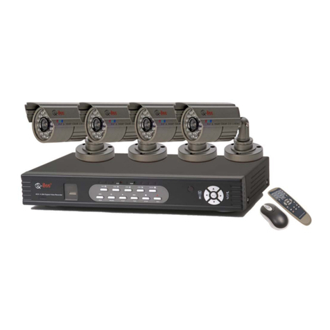
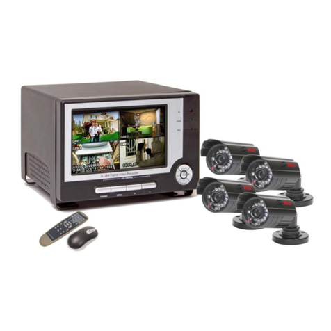
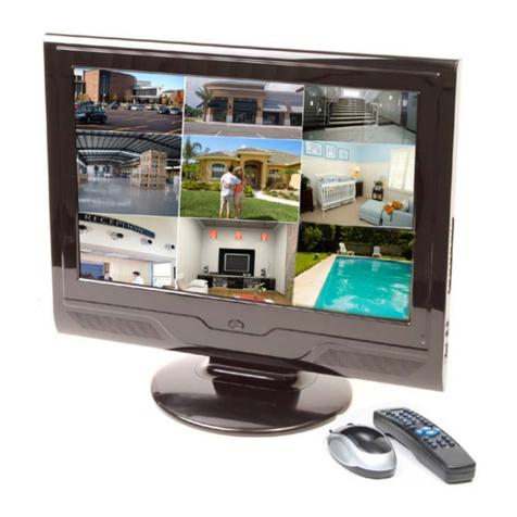
Q-See QR40198 User manual

QR40198 User Manual
19” LCD Observation System
Rev 4/14/2010

CONTACT US QR40198 User Manual
Please contact a Q-See support representative first regarding any additional information you need help with
regarding product features, specification or assistance with setup.
Please contact us using the following methods with questions about your Q-See product.
Q-See Products
8015 E. Crystal Dr.
Anaheim, CA 92807
Email:
Customer Service
cs@dpsi-usa.com
Technical Support
ts@dpsi-usa.com
Online live web chat visit:
www.q-see.com
Telephone:
Customer Service
1.877.998.3440 x 538
Technical Support
1.877.998.3440 x 539
Fax:
1.714.998.3509

SAFETY INSTRUCTIONS QR40198 User Manual
1. Electrical Safety
All installation and operation should conform to your local electrical safety codes.
We assume no liability or responsibility for any fires or electrical shock caused by improper handling or installation.
2. Transportation Security
Avoid heavy stress, violent vibrations or contact with water during transportation, storage and installation of this
system.
3. Installation
Keep upright. Handle with care.
Do not provide power to the combo DVR prior to completing installation.
Do not place objects on the combo DVR.
4. Qualified Service Technicians
Any examination and repair work should be done only be a qualified service engineer.
We are not liable for any problems caused by unauthorized modifications or attempted repairs.
5. Environment
This product works in a temperature range of 32°F to 104°F (0°C -40°C).
This combo DVR should be installed in a cool, dry place away from direct sunlight and flammable or explosive
substances, etc.
6. Accessories
Make sure to only use accessories recommended by Q-See.
Before installation, check the package to verify that all the components are included.
Contact your local retailer ASAP if something is broken in your package.
7. About the LCD Screen
During installation, do not push or squeeze the LCD or its rim as this may result in LCD damage.
During operation or storage be careful to avoid contact between hard objects and the LCD screen.
Keep the LCD screen clean by using a soft cloth to remove any dirt or smudges regularly. Never use ether-based
chemicals, alcohol or other chemical agents to clean your screen.
CAUTION!
RISK OF ELECTRICAL SHOCK!

WARRANTY INFORMATION QR40198 User Manual
Thank You for Choosing a Q-See Product!
All of our products are backed by a conditional service warranty covering all hardware for 12 months from the date of
purchase. Additionally, our products also come with a free exchange policy that covers all manufacturing defects for
one month from the date of purchase. Permanent upgrading service is provided for the software.
Liability Exclusions:
Any product malfunction or abnormalities in operation or damage caused by the following reasons are not within the
free service scope of our company:
(1) Equipment damage caused by improper operation.
(2) Improper equipment operation environment and conditions (e.g., improper power, extreme environmental
temperatures, humidity, lightning and sudden surges of electricity).
(3) Damage caused by acts of nature (e.g., earthquake, fire, etc).
(4) Equipment damage caused by the maintenance of personnel not authorized by Q-See.
(5) Product sold over 12 months ago.
In order to fulfill the terms of your warranty, you must complete the registration process after purchasing our product.
To do this, simply fill out the User’s Information Card below and fax or mail it in to us at the information listed below.
You can also register the product by going to the www.q-see.com website and clicking on the Register link.

PRODUCT REGISTRATION QR40198 User Manual
Customer Information Card
User’s Name
Mr./Mrs.
Company Name
Postal Address
Postal code
Phone Number
E-mail
Model Number of Product
Serial Number of Product
Purchase Date
Distributor
The material in this document is the intellectual property of Q-See.
No part of this manual may be reproduced, copied, translated, transmitted, or published in any form or by any
means without our company’s expressed written consent.
1.
Our products are under continual improvement and we reserve the right to make changes without
notice. No guarantee is given as to the correctness of its contents.
2. We do not accept any responsibility for any harm caused by using our product.
3.
The product picture may differ from the actual product, which is only for your reference. The
accessories may be different according to the region you purchased our product. For more
information on specific accessories, please contact your local distributor.
Copyright Reserved

TABLE OF CONTENTS QR40198 User Manual
CONTENTS
Chapter 1: DVR Features....................................................................................................................1
Chapter 2: Layout ...............................................................................................................................2
2.1: Front Panel...................................................................................................................................................................2
2.2:Rear Panel ....................................................................................................................................................................3
2.2.1: Multi I/O ‘L’Adapter................................................................................................................................................4
2.2.2: Remote Control .....................................................................................................................................................5
2.2.3: Mouse Operation...................................................................................................................................................5
Chapter 3: DVR Installation................................................................................................................6
3.1: Hard Drive Installation..................................................................................................................................................6
3.2: Connecting Your DVR to Cameras and a Monitor .......................................................................................................6
3.3: Connecting the Power Supply......................................................................................................................................6
Chapter 4: DVR Boot-Up.....................................................................................................................7
4.1. System Initialization .....................................................................................................................................................7
4.2. Main Interface...............................................................................................................................................................7
Chapter 5: DVR Menu .........................................................................................................................8
5.1: Main Menu At-a-Glance ...............................................................................................................................................8
5.2: Main Menu....................................................................................................................................................................9
5.2.1: Camera Setup .......................................................................................................................................................9
5.2.2: Record Setup.......................................................................................................................................................10
5.2.3: Network Setup..................................................................................................................................................... 11
5.2.3.1: DHCP............................................................................................................................................................ 11
5.2.3.2: PPPoE .......................................................................................................................................................... 11
5.2.3.3: STATIC..........................................................................................................................................................12
5.2.3.4: PORT FORWARDING..................................................................................................................................13
5.2.3.5: Pop-Ups & ActiveX Controls.........................................................................................................................14

TABLE OF CONTENTS QR40198 User Manual
5.2.4: Recording Search................................................................................................................................................16
5.2.5: Backup Recorded Files .......................................................................................................................................17
5.2.6: Multi Player..........................................................................................................................................................17
5.2.7: Device Management............................................................................................................................................19
5.2.7.1: HDD Management........................................................................................................................................20
5.2.7.2: Alarm Set......................................................................................................................................................21
5.2.7.3: PTZ Setup.....................................................................................................................................................23
5.2.7.4: Mobile Setup.................................................................................................................................................23
5.2.7.5: Mobile Phone Access ...................................................................................................................................24
5.2.7.6: Motion Detect................................................................................................................................................29
5.2.8: System Function..................................................................................................................................................29
5.2.8.1: Time Set........................................................................................................................................................29
5.2.8.2: Password......................................................................................................................................................30
5.2.8.3: Video Setup ..................................................................................................................................................30
5.2.8.4: Language......................................................................................................................................................30
5.2.8.5: Info................................................................................................................................................................30
5.2.8.6: System Maintenance....................................................................................................................................30
5.3: Menu Lock..................................................................................................................................................................31
5.4: Video Search..............................................................................................................................................................31
5.5: PTZ Control................................................................................................................................................................31
5.6: Record........................................................................................................................................................................31
5.7: Stop Recording...........................................................................................................................................................31
Chapter 6: Net-Viewer Program.......................................................................................................32
6.1: Enable Plug-Ins and Log-In to Net-Viewer.................................................................................................................32
6.2: Main Interface of Net-Viewer......................................................................................................................................32
6.2.1: Menu....................................................................................................................................................................33
6.2.1.1: Live ...............................................................................................................................................................33
6.2.1.2: Replay...........................................................................................................................................................33
6.2.1.3: Setup ............................................................................................................................................................33
6.2.1.4: Logging Out of Net-Viewer ...........................................................................................................................35
TABLE OF CONTENTS QR40198 User Manual
6.2.2: PTZ and Live Play Controls.................................................................................................................................35
Chapter 7: Specifications.................................................................................................................36
Chapter 8: Appendix.........................................................................................................................37
8.1: Operation Function Table...........................................................................................................................................37
8.2: Setting up Alarm Record Mode ..................................................................................................................................38
8.3: Troubleshooting..........................................................................................................................................................39
8.4: System Connections ..................................................................................................................................................40
8.5: Accessories Included .................................................................................................................................................41

DVR FEATURES QR40198 User Manual
1 | Page
Chapter 1: DVR Features
Function Brief Description
Real-Time
Monitoring Supports Real-Time Surveillance via Monitor
Save Files DVR Saves Real-Time Recording of Image Files to HDD
Backup Files Supports DVR Backup of Recorded Image Files via USB Flash Drive and Hard Drive
Playback Files
Supports DVR single CH and Multiple CH Playback of Recorded Files
Network
Operation Supports Remote Surveillance by Multiple Users Simultaneously
Alarm Setting Supports HDD & video input alarm management and external alarm signal inputs.
Mouse
Operation Supports Mouse Operation for Faster Menu Navigation.
PTZ Control Supports PTZ camera operations through RS-485.
Other Features:
•H.264 Video Compression Format; Supports CIF, D1 and HD1 Resolution
•ADPCM Audio Compression Format
•Windows Graphics Interface
•Menu Status Notification
•Multiple Operation (Preview, Recording, Backup, Network Surveillance and Mobile Phone Monitoring Simultaneously)
•Supports Double Encoded Bit Network Transmission
•Supports Remote Live Viewing Via 3G Mobile Networks
•Supports Zoom In/Out And Dwell Time Display
•Adjustable Video Package Time
•Multiple Alarm Record Mode
•Rear USB 2.0 Ports For Back-Up, Upgrade and Mouse Operation
•IR Remote Control Operation
•Multiple Language OSD (On Screen Display)
•Supports Auto Maintenance

LAYOUT QR40198 User Manual
2 | Page
Chapter 2: Layout
2.1: Front Panel
Item Buttons/
Indicators Marks Functions
1 ON/OFF ON/OFF Turns the screen on or off.
2 MENU MENU Opens the Main Menu screen.
3 Up UP Move up
4 Down DOWN Move Down

LAYOUT QR40198 User Manual
3 | Page
2.2:Rear Panel
Item
Number Name/Symbol Description Function
1 DC12V
Power Port Power Supply - DC12V 5A
2 LAN Ethernet Port
Intranet and Internet Connection
(RJ-45 Interface)
3 USB Port USB Mouse Connection
4 USB 2.0 Port USB Device (Flash Drive, Hard
Drive) Connection
5 AUDIO
-OUTPUT- Audio Out
Connection Connect signal output (RCA
interface)
6 -VIDEO
OUTPUT- Video Out
Connection Connect Monitor Output (BNC
Interface)
7 EXTERNAL I/O
EXTERNAL I/O
Connection
Connects to the included “L”
Adapter for Connecting Cameras
and PTZ Enabled Cameras.
8 Power Switch
Powers the DVR On/Off
Completely
I
О

LAYOUT QR40198 User Manual
4 | Page
2.2.1: Multi I/O ‘L’Adapter
(Please see actual product for detail)
Video in Cables are marked with Channel numbers Ports on Alarm block are:
VIN1 through VIN8 Alarm Out
Alarm Out
Sensor 1
Sensor 2
Sensor 3
Sensor 4
Sensor 5
Sensor 6
Sensor 7
Sensor 8
RS485 +
RS485 –
Item Physical Jacks Connection method
1 Audio Input Connects to the audio output of an audio enabled camera
2 Video Inputs Connect to the signal output of cameras
3 PTZ Outputs Connect to the PTZ input of any Pan-Tilt-Zoom enabled camera

LAYOUT QR40198 User Manual
5 | Page
2.2.2: Remote Control
1 1-8 Channel Select 1-8 ; Numeric key
2 9,0 Numeric Key
3 ALL Preview all Channels
4 MENU Enter/Exit Main Menu
5 ▲Up Key
6 ▼Down Key
7
◄/►
Left / Right Key
8 SEL Select Key/ Edit Key
9
Rewind
10
►
Play Recorded Events
11
Forward Key
12
●
Manual Recording
13
Pause / Frame Play
14
■
Manually Stop Recording or Playback
15 AUDIO PlayAudio from Selected Camera
16 MUTE Mute Audio
2.2.3: Mouse Operation
For your convenience, your Q-See DVR System can also be operated by a mouse in addition to the front panel
controls and remote control.
Action Function
Left Click
With your DVR in Menu Unlock mode, left clicking on your mouse opens a pop-up dialog menu that
allows you to access your programming and configuration settings. Some of the options available
by left clicking include :
•Edit your record settings.
•Playback recorded files.
•Access a pull-down menu.
•Control color and volume settings.
•Choose your system’s language settings.
•Double clicking the left key of your mouse maximizes the screen view.
Right Click
With your DVR in Live Display mode, right clicking will display a pop-up menu (See Picture 3) which
allows you to:
•Exit system programming and configuration mode.
•Close all configuration menu dialog boxes.
Sliding Mouse
•In Motion set mode, sliding the mouse will select the area of motion you wish to choose.
•In Color Set mode, sliding the mouse allows you to access and adjust the color control bar
and the volume control bar.

DVR INSTALLATION QR40198 User Manual
6 | Page
Chapter 3: DVR Installation
3.1: Hard Drive Installation
Caution:NEVER Install or remove the hard drive while the DVR is running!
The model has a Hard Disk Drive (HDD) drawer. Please use key provided to open the drawer and insert the HDD
as follows:
(1) Remove screws and open DVR upper cover carefully;
(2) Insert Power Cord and data cable securely into matching ports on hard drive;
(3) Put the upper cover back carefully, re-attach screws.
3.2: Connecting Your DVR to Cameras and a Monitor
Connect camera cable to the Video Input port of the DVR. Connect the monitor to the Video Output port of the
DVR using a BNC connector (See Rear Panel Section 2.2).
To connect a PTZ speed dome to your DVR System, connect your PTZ Camera data cables to your RS485 A & B
ports. See Chapter 5 for a more detailed account of PTZ Camera configuration instructions.
3.3: Connecting the Power Supply
Only use the power adapter supplied with your DVR System.Failure to do so may result in unforeseen system
failures.

DVR BOOT-UP QR40198 User Manual
7 | Page
Chapter 4: DVR Boot-Up
4.1. System Initialization
After connecting the power adapter the system will boot-up and start
initializing.
Picture 1
4.2. Main Interface After initialization, the system will display the main display screen.
When there are video inputs, live images from the cameras will be
displayed on the screen. You can use the mouse to double-click the
live image of any channel for full screen display; by double-clicking
again, the display will display all cameras.
On the main interface, you will be able to see current system date &
time, channel title, and recording status.
When there is no HDD installed in the DVR, or the HDD is not in
working condition, system will display “H” on the screen.
Picture 2
Press SEL button on the front panel or click the right mouse button and you will see the pop-up menu bar.It’s a short
cut to your most frequently used menus. Detailed information on the options in the pop-up menu bar will be available
in the chapter related to that option. Picture 3 shows the menu in multiple screen mode, Picture 3A shows it in single
screen mode, and Picture 3B shows the menu with password enabled in multiple screen mode.
Picture 3 Picture 3A Picture 3B

DVR MENU QR40198 User Manual
8 | Page
Chapter 5: DVR Menu
5.1: Main Menu At-a-Glance
Search
Camera
Record
System
Devices
Network
Main Menu Search
Playback
File List
HDD Management
Alarm Setting
PTZ Setting
Mobile Phone Setup
Motion
Color setup
User Password
System Information
Language Selection
System Maintenance
Video Setting
Time Setting
Autoseq Setup
Camera Title
Privacy Setup
Record Enable
Record Quality
Audio Record
Record Mode
Record File Size
DDNS Setup
Record Schedule
Area Setup
E-mail Setup
Backup
VGA Solution
Video Mode
Firmware Upgrade

DVR MENU QR40198 User Manual
9 | Page
5.2: Main Menu
The right-click menu in the Main Interface mode (Picture 3) allows you
to access the Main Menu interface (Picture 4). You can use the right
click function of the mouse or the Menu button on the front panel of
the DVR to enter into the Main Menu interface. Use the mouse or the
FWD and REW button on your DVR’s front panel or remote control to
navigate around the Main Menu Interface and select the icon of the
program you wish to access (See Picture 4). Use the ESC button on
your DVR’s front panel to return to the previous window of the Main
Menu interface. Set your management permissions, configure your
devices, customize your recording parameters, and access your
System Functions (such as time, date and passwords) through the
Main Menu Interface. You can also configure the controls for your
Camera, Network, HDD, Alarm, PTZ, & Mobile Phone controls
through the Main Menu Interface.
5.2.1: Camera Setup To set up the display name and position display of each camera, go to
[Main Menu Camera] and you will receive a Camera Setup
interface (Shown as Picture 5). Through the Camera Setup interface,
you are able to choose a name for each of your connected cameras
up to 8 characters long. The Camera Setup interface (Picture 5) also
gives you the ability to choose which camera channels you wish to
enable live viewing of and which camera channels you wish to set up
with the ability to record. The Camera Setup interface is also where
you would set your DVR system up to automatically rotate through
your camera views and adjust the image brightness, saturation,
contrast and hue settings of each camera as well.
To set your system up to automatically rotate through your viewed
cameras in the Camera Setup interface, click on the [AUTOSEQ]
button (Picture 5). This will initiate a pop up AUTO ROTATION sub
menu (Picture 5A) that will allow you to choose the amount of time you
would like to view each camera from a drop-down list. Default
rotation time is set at 5 Seconds. However, you can adjust this setting
to range anywhere from 0 to 10 Seconds.
To adjust the image brightness, saturation, contrast and hue settings
of each camera, click on the [SETUP] button Under the column titled
“COLOR” on the Camera Setup interface (Picture 5). This will initiate
a pop-up [COLOR SETUP] sub menu where you can make your
desired changes (Picture 5B).
(Picture 4)
(Picture 5)
(Picture 5A)

DVR MENU QR40198 User Manual
10 | Page
Please note that any modifications you make through the Camera
Setup interface will not be applied until you click the [APPLY] button at
the bottom of the dialog box (Picture 5). Once you do this, you will
then be prompted to save your settings, and you must click [OK] in
order for the changes to take effect. If you wish to abort the changes
you made, simply click the [Exit] button on the bottom of your dialog
box (Picture 5). By clicking on the [DEFAULT] button at the bottom of
your Color Setup dialog box (Picture 5) all system default values will
be reset to their original factory installed settings.
5.2.2: Record Setup
The right click menu in the Main Interface mode (Picture 3) allows you
to access the Main Menu interface (Picture 4). To set up the recording
parameters and settings of your DVR, go to [Main Menu] [Record] to
enter into the [Record Setup] menu (Picture 6).
The [Record Setup] menu (Picture 6) allows you turn the recording
status for each camera channel on and off, set the recorded image
quality and enable audio recording. This menu also allows you to
schedule your recording times and set your recording file sizes.
The [RECORD] button on your Record Setup Menu (Picture 6) allows
you to turn each camera channel’s recording ability on or off. The
[QUALITY] button gives you the option of choosing the quality of your
recorded images from a drop down list for each individual camera
channel. The [AUDIO] button allows you to turn the audio input on or
off. When the audio is turned off, the DVR system will not record
audio and you will not hear sound during playback of your recorded
events.
The [REC MODE] drop down list allows you to setup the system to
record 24 hours a day, on a set schedule or when motion is detected.
The [FILE SIZE] drop-down list allows you to set the maximum
recording time for all recorded files to be 15, 30, 45 or 60 minutes.
TIME SCHEDULED RECORDING: To set your system up to record on a time schedule, choose the TIME
SCHEDULE RECORD option on the REC MODE drop down list. To record 24 hours a day, choose the ALWAYS
option from the REC MODE drop down list. To record on motion or a set schedule, select Time Schedule Record
and click the “Schedule” option. Choosing this option will initiate a pop-up SCHEDULE interface which will allow you
to customize your scheduling options as illustrated by Picture 6A. You can choose from a pull down menu at the top
of your SCHEDULE interface to adjust the recording options for all channels or from the channels specified in the
drop down menu if you prefer to set the recording parameters for each individual channel separately.
(Picture 5B)
(Picture 6)
(Picture 6A)

DVR MENU QR40198 User Manual
11 | Page
(Picture 8)
You are also given the option of setting up the date parameters of your scheduled recordings by choosing from the
drop down menu on the bottom of your Schedule interface in the “From” and “To” options. Checking the ALARM
(motion record), GENERAL (always record) and NO RECORD boxes will allow you to further customize options for
your scheduled recordings.
If you decide that you do not wish to customize your system recording schedule, the Default recording schedule is as
follows:
Hr 01:00 am - 07:59 am: No recording (Not recording)
Hr 08:00 am - 18:59 pm: Normal recording
Hr 19:00 pm - 00:59 pm: Alarm recording (Record on activity or alarm only)
5.2.3: Network Setup
The right click menu in the Main Interface mode (Picture 3) allows you
to access the Main Menu interface (Picture 4). To set up the Network
settings of your DVR, go to [Main Menu] [Network Set] to enter into
[Network Setup] menu (Picture 7).
From the Network Setup menu (Picture 7), you can choose your
Network Type (DHCP, PPPoE, or Static), Port and Web Port (80 and
9000 by default) from a drop down list. Once you have configured
these, you can then view the DVR remotely over a network or the
internet.
5.2.3.1: DHCP
When selecting DHCP as your Network type, your Router will allocate
a DVR IP address automatically once you exit the Network Setup
menu. Write down the address assigned by your Router. It is
recommended you switch to the “Static” Network Type and enter the
address information here to avoid any discrepancies that might occur
in the event your Router auto generates a different address in the
future.
5.2.3.2: PPPoE
When selecting PPPoE as your Network type, you will need to input a
user and password provided by your internet service provider. Once
you have obtained those settings from your internet service provider,
you will need to set your web port as illustrated in Picture 8.
(Picture 7)

DVR MENU QR40198 User Manual
12 | Page
(Picture 9)
5.2.3.3: STATIC
When selecting Static as your Network type, you will
need to set the Network setting on the DVR to match
settings of your Router. To do this, bring up the
command prompt on any computer attached to your
Router by typing cmd into your Run program (Picture 9).
Type in ipconfig at the prompt (see red arrow on Picture
9) to access the router settings. Write down the gateway
and subnet mask numbers (Green arrows on Picture 9)
so you can enter them into the network settings of the
DVR (Picture 10).
To set up the Network settings of your DVR, go to [Main
Menu] [Network Set] to enter into [Network Setup]
menu (Picture 10). Select the Static option from the
“TYPE” drop down list on the Network Setup menu
(Picture 10). For the DVR’s IP address, use the same
first 3 sets of numbers as the gateway and select a
fourth set of numbers that is different than any other
device attached to the same router. If the IP address of
your computer in the ipconfig (BLUE arrow in Picture 9)
was a single or two digit number you should be ok with
any three digit number, if the computer IP address ends
with a number in the 100s then you should use a
number in the 200’s. Once you enter the addresses hit
OK button.
At the bottom of the NETWORK SETUP window there is
an option to setup the DVR to be accessed through a
DDNS service. Clicking on this button will pull up a
screen as seen in Picture 11. Through here, you can set
your DVR up to use a Dynamic Domain Name Service.
Keep in mind that a dynamic address can change from
time to time depending upon your service provider. In
the event that it does change, you will need to go to a
website such as www.myipaddress.com from a
computer attached to the same router as the DVR to
figure out what that new IP address is.
To avoid a change in IPAddress by your Internet Service
Provider, you can either ask your service provider for a
static IP Address or use a dynamic domain name
service to get a domain name that can be linked to your
dynamic address. You can register for a domain name,
user name, and password through our company’s
myq-see.com website. By registering, you can then
enter your dynamic domain name into an Internet
Explorer browser instead of an IP address and be
directed to whatever the current dynamic IP address is,
so that you can always access the DVR by entering the
same address. This DVR also supports the DDNS
service provided by dyndns. You can get more
information on how to use these services from the
myq-see.com or www.dyndns.com website.
(Picture 10)
(Picture 11)
Table of contents
Other Q-See Security System manuals

Q-See
Q-See QTT442266--88003 User manual

Q-See
Q-See QR4074-418 User manual

Q-See
Q-See QSW18C User manual

Q-See
Q-See QR4074-426 User manual

Q-See
Q-See QSDL506W User manual

Q-See
Q-See QC804-261-1 NVR User manual

Q-See
Q-See QT5132 User manual

Q-See
Q-See QT528-435 User manual

Q-See
Q-See QR4274-418 User manual

Q-See
Q-See QT548-841-5 Operating and safety instructions

Q-See
Q-See QH50DVR8C User manual

Q-See
Q-See DVR User manual

Q-See
Q-See QR4174-418 User manual

Q-See
Q-See QR208--811 User manual

Q-See
Q-See QR4074-411 User manual

Q-See
Q-See qr404-411 User manual

Q-See
Q-See QR424-403 User manual

Q-See
Q-See QS SERIES User manual

Q-See
Q-See QSDS14273X User manual

Q-See
Q-See QSD004C4-250 User manual