PF Conveyors | Installation, Operation & Maintenance Manual 5
Conveyor Installation / Instalación de cinta transportadora
Lock-out power. Emergency stops are required and must be installed as part of the tables. The circuitry for the emergency stop is integrated into the conveyor’s
control panel. In addition, the installer must provide a lockable means of power isolation.
Bloquear la corriente eléctrica. Se requieren paradas de emergencia y se deben instalar como parte de las mesas. Los circuitos para la parada de emergencia están integra-
dos a la carcasa del controlador de la cinta transportadora. Además, el instalador debe proporcionar un medio de bloqueo que permita aislar la corriente eléctrica.
uInstall Conveyors In Tables / Instalar las cintas transportadores en mesas
EN
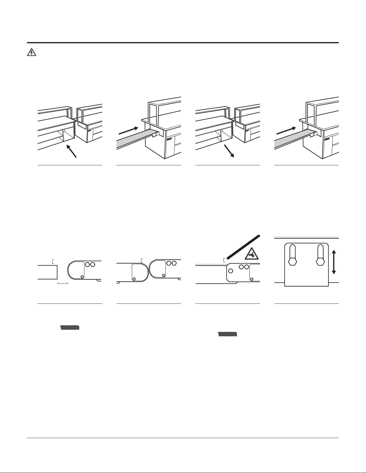
1Separate the tables so the
service cavity within the ECU
table is accessible.
2Slide the ECU conveyor, tail
first, into the ECU table. 3Move the tables back to-
gether to allow access to the
PREP tables service cavity.
4Slide the PREP conveyor, tail
first, into the PREP table.
ES Separar las mesas para que la
cavidad de servicio en la mesa ECU
quede accesible
Deslizar la cinta transportadora ECU,
comenzando por la parte trasera, en
la mesa ECU
Volver a colocar juntas las mesas
dejando libre el acceso a la cavidad
de preparación
Deslizar la cinta transportadora de la
mesa de preparación, comenzando
por la parte trasera, en la mesa de
preparación
uCheck Conveyor Elevations /Vericar alturas de la cinta transportadora
25mm
OAT
3-5mm 3-5mm
EN
1Confirm the discharge end of
the ECU table conveyor is 3-5
mm above the OAT surface.
WARNING
Leave a 25 mm gap between the
conveyor and the OAT; a smaller
gap creates a pinch hazard.
2Confirm that the conveyors
transition point, at the end of
the PREP table, is 3-5 mm above
the ECU table. The conveyor bear-
ing housings should be between
0-5 mm apart at transition.
3Confirm that the top of the
PREP tables’ conveyor belt
is 3-5 mm below the bottom of
the chute.
WARNING
The chute and conveyor create
a pinch point; proper guarding
must be installed.
4Make adjustments as needed.
The mounting height can be
adjusted by loosening the hex head
screws with a 10 mm wrench.
ES Conrmar que el extremo de des-
carga de la cinta transportadora de la
mesa ECU esté 3-5 mm por encima
de la supercie de la mesa de armado
de pedidos (OAT)
ADVERTENCIA
Dejar una brecha de 25 mm entre
la cinta transportadora y la mesa de
armado de pedidos, una brecha más
pequeña crea un peligro de pellizco
Conrmar que las cintas transporta-
doras en el extremo de transición de
la cinta transportadora de la mesa
de preparación está 3-5 mm por
encima de la cinta transportadora
ECU; las carcasas de los cojinetes
de las cintas transportadoras deben
estar a una distancia de 0-5 mm en
la transición.
Conrmar que la parte superior de la
cinta transportadora de la mesa de
preparación esté 3-5 mm por debajo
del conducto de descarga
ADVERTENCIA
El conducto de descarga y la cinta
transportadora crean un punto de
pellizco, se debe instalar protección
adecuada
Hacer los ajustes que sean
necesarios. La altura del montaje se
pueden ajustar aojando los tornillos
de cabeza hexagonal con una llave
de 10 mm