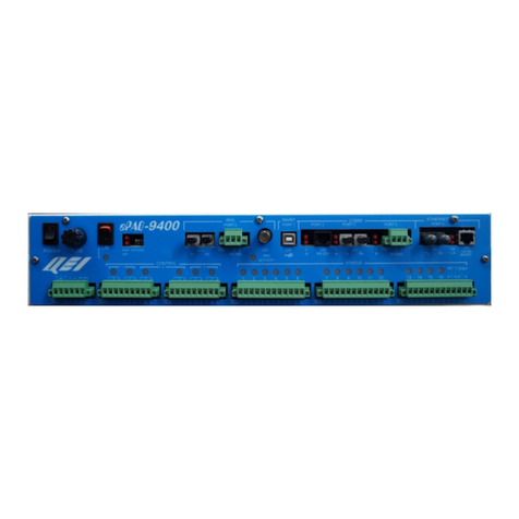
QEI ePAQ-942 Series User manual

UG-1071
ePAQ-9410 / ePAQ-9420
User’s Guide
December 2018

E ePAQ-9410 / ePAQ-9420 User’s Guide UG-1071
Copyright © 2017 by QEI
UG-1071 ePAQ-941x / ePAQ-942x User’s Guide
ALL RIGHTS RESERVED
NOTICE
The information in this document has been carefully checked and is believed to be
accurate. However, no responsibility is assumed or implied for inaccuracies.
Further- more, QEI reserves the right to make changes to any products herein
described to improve reliability, function or design. QEI does not assume liability
arising out of the application or use of any product or circuit described herein; neither
does it convey any license under its patent rights nor the rights of others.
This manual and all data contained constitute proprietary information of QEI and
shall not be reproduced, copied or disclosed to others, or used as the basis for
manufacture without written consent of QEI.
45 Fadem Road
Springfield, NJ 07081
Phone: (973) 379-7400
Fax: (973) 379-2138
Web Site: www.qeiinc.com

UG-1071 ePAQ-9410 / ePAQ-9420 User’s Guide
ePAQ-9410/ePAQ-9420 User’s Guide Revisions
i
Revisions
Revision
Description
Date
A
Initial Release
Feb 2012
B
Changed position of L/A and TX
labels for Ethernet copper port
LEDs (section 5).
Apr 26 2012
C
Clerical changes (pg 6 and 28).
Specify RS-485 termination values
in section 6. Assign P/Ns for
Configwiz 2.0 software and
manual in section 11. Revise
ordering information section 13.
July 24 2012
D
Formatting Update
July 30, 2013
E
Various Clerical changes.
Nov 14, 2013
F
DIP switch update, ePAQ9425
model added
Jul 29, 2015
G
Formatting Update
Feb 24, 2016
H
Section 13 Ordering Information
June 7, 2017
I
Updated QEI Address
December
2018


ePAQ-9410 / ePAQ-9420 User’s Guide UG-1071
ePAQ-9410 / ePAQ-9420 User’s Guide Contents
i
Contents
1General Description .................................................................1
1.1ePAQ-9410 Features...........................................................1
1.2 ePAQ-942x Features...........................................................2
2Specifications...........................................................................3
3Input Power Connections ........................................................5
4Power Switch and Fuse ...........................................................6
4.1 Dip Switches........................................................................6
5LED Indicators..........................................................................7
5.1 Diagnostics..........................................................................7
5.2 Comm Port LEDs.................................................................8
6Communications Ports..........................................................10
6.1 Ports 1/2 (J1B/J1A): Modem.............................................10
6.1.1 Connections........................................................10
6.1.2 Recommended Interface cable type:...................11
6.1.3 Surge Protection/Isolation :.................................11
6.2 Ports 3/4/5/6 (J2B/J2A/J2D/J2C): RS-232/RS-485 ...........12
6.2.1 Connections:.......................................................12
6.2.2 Redundancy Capability:......................................13
6.2.3 Isolation/Surge protection ...................................13
6.2.4 RS-485 Termination............................................13
6.3 Port 7 (J3) : Serial/IRIG-B Fiber.........................................14
6.3.1 Introduction.........................................................14
6.3.2 Connections........................................................14
6.3.3 Recommended Cable Type.................................15
6.4 Port 8 (J7B): IRIG-B RS-485..............................................15
6.4.1 Introduction.........................................................15
6.4.2 IRIG-B Standards and functionality.....................15
6.4.3 Connections........................................................16
6.4.4 Recommended cable type ..................................16
6.4.5 Surge protection/Isolation ...................................17
6.4.6 Termination.........................................................17
6.5 Ports 9/10/11 (J7A/J7C/J7D): RS-422 ...............................18
6.5.1 Introduction.........................................................18
6.5.2 Connections........................................................18
6.6 Ports 12/13 (J8B/J8A): RS-232 (Bit/Byte) Ports.................19
6.6.1 Introduction.........................................................19
6.6.2 Connections:.......................................................20
6.7 Port 14/15 (J10/J11): 100 Base FX Ethernet Fiber.............21
6.7.1 Introduction:........................................................21

E ePAQ-9410 / ePAQ-9420 User’s Guide UG-1071
6.7.2 Connections :......................................................21
6.7.3 Recommended Cable Type.................................21
6.8 Ports 16/17/18/19 (J12B/A/D/C): 10/100BaseTX Ethernet.22
6.8.1 Introduction.........................................................22
6.8.2 Connections........................................................22
6.8.3 Comm Redundancy Applications ........................23
6.9 Ports 20 thru 35 (J13A thru J16D): ....................................24
6.9.1 Introduction.........................................................24
6.9.2 RS-232/RS-485 Connections (RJ45): .................24
6.9.3 RS-232/RS-485 Connections..............................25
6.9.4 Recommended cable type :.................................25
6.9.5 Surge protection/Isolation ...................................25
6.9.6 RS485 Termination:............................................26
6.9.7 Fiber Connections :.............................................26
7Modulated Irig-B Interface (BNC, J9)....................................26
7.1 Introduction........................................................................26
7.2 Connections.......................................................................27
7.3 Relevant Standard.............................................................27
7.4 Recommended cable type.................................................27
8USB Maintenance Port...........................................................28
8.1 Introduction........................................................................28
8.2 Connections:......................................................................28
9SD Card Interface ...................................................................29
9.1 Introduction........................................................................29
9.2 Connections.......................................................................29
10 USB Host Ports.......................................................................30
10.1 Introduction........................................................................30
10.2 Connections.......................................................................30
11 Software ..................................................................................31
12 Mechanical Outline.................................................................32
13 Ordering Information..............................................................34

ePAQ-9410 / ePAQ-9420 User’s Guide UG-1071
Copyright © 2017 QEI General Description
1
1 General Description
The ePAQ-9410 and ePAQ-9420 (ePAQ-94XX) Multifunction Gateways are part of the
QEI family of Distribution Automation Products. They are housed in a 19 inch 3U rack-mount
enclosure, and are intended for installation in harsh electrical utility sub-station environments.
All connections, switches, and indicators are accessible from the front panel. The ePAQ-9420
provides additional communications capabilities vs the ePAQ-9410. Both units include an
additional option for more comm ports, using the eXP-9430.
The ePAQ-94XX is configured using QEI’s ConfigWiz 2.0 Configuration Program, and a
ePAQ-94XX Template. Refer to the ConfigWiz 2.0 User’s Guide (UM-2018) and the ePAQ-
94XX addendum contained in the same manual.
1.1 ePAQ-9410 Features
The following features are provided on the ePAQ-9410 :
Wide input voltage range (48-125Vdc/120-277Vac)
Two Bell 202T modems (bit or byte oriented).
Option DIP Switches (front panel accessible)
System Indicator LEDs.
Front panel USB maintenance port for Windows based diagnostic and configuration software.
SD Memory Card support.
Irig Time interface (modulated Transmit/Receive BNC, digital RS-485 or Serial Fiber).
NTP time (peer or client) or PTP (Precision Time Protocol.
Three High Speed RS-422 ports (RJ45 x3) for I/O expansion.
Two RS-232 ports (bit or byte oriented) (RJ45 x2)
Four RS-232/RS-485 combo ports (RJ45 x4)
Two USB Host ports for thumb drives or other bulk storage, etc.
Two Ethernet ports 100BaseFX (Multimode ST Connectors)
Four Ethernet ports 10/100BaseT (RJ45 x4).
All communications ports are available via RJ45 connectors, and have LEDs to indicate
communications status (TX, RX, Link, H/S). The RS-232/RS-485 combo ports are substation
hardened.

ePAQ-9410 / ePAQ-9420 User’s Guide UG-1071
2
General Description Copyright 2017 QEI
Ethernet and serial fiber ports have ST connectors for Multimode Fiber with TX/RX LED
indicators.
RS232/RS485 combo ports can be tri-stated for redundancy capability between two
units.
USB Type B maintenance port supports Windows based PC software for unit
configuration and diagnostics.
The ePAQ-94XX is housed in a 19 inch rack mount (or surface mountable) 3U
enclosure. It includes a universal power supply that accepts 48 to 125Vdc, or 120/240/277Vac
50/60Hz input.
1.2 ePAQ-942x Features
The ePAQ-9420 includes all of the ePAQ-9410 features, while providing an additional
sixteen RS-232/RS-485 ports (via RJ45 connectors) or eight serial fiber ports (via Multimode
ST connectors). Like the ePAQ-9410, the additional ePAQ-9420 RS-232 ports can be tri-stated
for redundancy applications, when two ePAQ-9410/20 device ports are wired in parallel. There
is an interprocessor link, which allows a slave ePAQ to take over the operation of attached RS-
232 devices, when the heartbeat goes missing from the Master ePAQ
The ePAQ-9425 is similar to the ePAQ-9420, but provides all 16 upper level ports to be
in the rear of the device as RS-232 / Rs-485 DB9 ports. It will only come in one configuration
of the rear port of 8 isolated and 8 non isolated DB 9 ports

ePAQ-9410 / ePAQ-9420 User’s Guide UG-1071
Copyright © 2017 QEI Specifications
3
2 Specifications
General
Description
Microprocessor
Atmel IMX357 ARM11 Processor,
Communications Ports
Port 1, 2 : Modem
Interface
2 or 4-Wire Comm Line (600 Ohm Xfmrs)
Protocols
Asynchronous Bit or Byte Oriented
Bit Rate
300 or 1200 baud
Connectors
RJ45 x2 (J1A, J1B)
Port 3, 4, 5, 6: RS232/485
Interface
RS-232 TX, RX, RTS, CTS & COM / RS-485 A+, B-, COM.
Protocols
Asynchronous Byte Oriented
Bit Rate
1200 to 115.2Kbps
Connectors
RJ45 x4 (J2A, J2B, J2C, J2D)
Port 7: IRIG/Serial
Interface
TX, RX, 10BaseFL Serial Fiber
Protocols
Asynchronous
Bit Rate
1200 to 115.2Kbps
Connectors
ST Connectors (J3-TX, J3-RX)
Port 8 : IRIG
Interface
RS-485 A+, B- COM
Protocol
IRIG-B
Connector
RJ45 (J7B)
Port 9, 10, 11: RS-422/485
Interface
RS-422/RS-485 A+,A-,B+,B-
Protocol
Factory I/O Expansion
Bit Rate
Up to 2 Mbps
Connectors
RJ45 x3 (J7A, J7C, J7D)
Port 12, 13: RS-232
Interface
RS-232 TX, RX, RTS, CTS, COM, TXCLK, RXCLK, PTT
Protocols
Asnchronous/Synchronous
Bit Rate
Up to 115.2kBps , and per protocol.
Connectors
RJ45 x2 (J8A, J8B)
Modulated Irig-B Interface
Interface
Irig-B Modulated Input
Protocol
Irig-B
Connector
BNC Connector, Female (J9)
Port 14, 15: 100BaseFX
Interface
Ethernet IEEE 802.3u compliant
Protocols
IP (TCP, UDP)
Bit Rate
Up to 100 Mbps
Connectors
ST, multimode (J10, J11)

ePAQ-9410 / ePAQ-9420 User’s Guide UG-1071
4
Specifications Copyright 2017 QEI
Port 16,17,18, 19: 100BaseTX
Interface
Ethernet IEEE 802.3 compliant, Auto MDI/MDI-X
Protocols
IP (TCP, UDP)
Bit Rate
Up to 100 Mbps
Connector
RJ45 x4 (J12A, J12B, J12C, J12D)
USB Host Port
Protocol
USB 2.0
Connectors
USB Type A x2 (J6)
USB Maintenance Port
Protocol
USB 2.0
Connectors
USB Type B (J5)
Port 20 to 35: RS232/RS485
(ePAQ-9420 / 9425 Only)
ePAQ-9420 Option, ePAQ-9425: 16 (Sixteen) RS-
232/RS485 ports.
Interface
RS-232 TX, RX, RTS, CTS & COM / RS-485 A+, B-, COM.
Protocols
Asynchronous Byte Oriented
Bit Rate
1200 to 115.2Kbps
Connectors
RJ45 x16 (J13A, B, C, D thru J16A, B, C, D)
DB9 x 16 (J13A, B, C, D thru J16A, B, C, D)
Port 20/22/24/26/28/30/32/34
(ePAQ-9420 /Only)
ePAQ-9420 Option: 8 (Eight) Serial Fiber ports (10BaseFL)
Interface
TX, RX, 10BaseFL Serial Fiber
Protocols
Asynchronous
Bit Rate
1200 to 115.2Kbps
Connectors
ST Connectors (J20/22/24/26/28/30/32/34 TX, RX)
SD Card Interface
Cards Supported
SD, SDHC
Max Capacity
16 GB
Supported Mfgr/Model
TBD
Power Input
Voltage
48,125VDC, 120/240/277 VAC
Current
50VA max (ePAQ-9420).
Connector
6-pin terminal block (TB1)
Note : 277 VAC Tol +/- 5% Max; Other inputs Tol +/- 10%
Environment
Temperature
-40 to +75oC
Humidity
5 to 95% @ +70oC, non-condensing
EMI
C37.90.1, Various IEEE 1613-2009 Tests
Physical Dimensions
Mounting Dimensions
17.3” W x 5.25” H x 10.0” D without mounting brackets
19.0” W x 5.25” H x 10.0” D w/ rack mounting brackets

ePAQ-9410 / ePAQ-9420 User’s Guide UG-1071
Copyright © 2017 QEI Input Power Connections
5
3 Input Power Connections
The ePAQ-94XX accepts a variety of input voltage sources, such as 48 and 125Vdc. The
unit may also be powered by 120, 240 or 277Vac.
Input power connections are made at terminal block TB1:
H+L- L- H+
TB1 PIN#
Name
Description
1
Chassis Connection
2
Chassis Connection
3
L-
DC Neg / AC Neut
4
L-
DC Neg / AC Neut
5
H+
DC Pos / AC Line
6
H+
DC Pos / AC Line

ePAQ-9410 / ePAQ-9420 User’s Guide UG-1071
6
Power Switch and Fuse Copyright 2017 QEI
4 Power Switch and Fuse
The ePAQ-94XX includes a front panel mounted rocker switch for power on/off functions. A
front panel fuse is also provided. :
FRONT PANEL
DESCRIPTION
PWR
Turns the ePAQ-94XX on and off
I = Power on
O = Power off
FUSE
ePAQ-9410 = 2 Amp Slo-Blo 250VAC 3AB Ceramic
Littelfuse 0326002 (QEI P/N 10-003669-048)
ePAQ-9420 = 3 Amp Slo-Blo 250VAC 3AB Ceramic
Littelfuse 0326003 (QEI P/N 10-003669-049)
4.1 Dip Switches
Four dip switches are available for application specific options (see the appropriate
ConfigWiz addendum for further information).

ePAQ-9410 / ePAQ-9420 User’s Guide UG-1071
Copyright © 2017 QEI LED Indicators
7
S1 PWR
L2
PWR
HBT
L3
L1
L4
OPTIONS
1 2 34
FRONT PANEL LABEL
S1
Dip switch bank of 4 switches.
Switches are application specific (see the appropriate
ConfigWiz2 addendum for further information).
DIP switch 1: Safe Mode. Requires a power cycle to enable.
Up (off) - Normal mode. IP address is that configured
in the NetConfig component in the ConfigWiz2
software
Down (on) - Safe mode. IP address is set at
192.168.1.199. Note: Be aware of other RTUs that
may be in safe mode on the same network as they
will share the same IP address.
5 LED Indicators
5.1 Diagnostics
S1 PWR
L2
PWR
HBT
L3
L1
L4
OPTIONS
1 2 34
LED Name
Function
HBT
Heartbeat –This LED will flash on and off at a 1 Hz rate to indicate
that the microprocessor circuitry is functional. The LED may flash at

ePAQ-9410 / ePAQ-9420 User’s Guide UG-1071
8
LED Indicators Copyright 2017 QEI
a different rate for diagnostics.
PWR
Power supply voltage monitor. This LED will light continuously to
indicate CPU logic power.
L1/L2/L3/L4
Spare LEDs. For future applications.
5.2 Comm Port LEDs
Serial Communications Ports RJ45 2x2:
Serial Communications Ports RJ45 1x4:
RX
TX
LEDs
TX RX TX RX TX RX
100BaseTX Ethernet Ports RJ45 2x2:

ePAQ-9410 / ePAQ-9420 User’s Guide UG-1071
Copyright © 2017 QEI LED Indicators
9
10BaseFL Fiber Serial Ports:
RXTX
RX
TX
LEDs
TX
RX RX
TX
10/100BaseFX Ethernet Fiber Ports:
RX
TX TX RX
100BASE FX 100BASE FX
L/A
TX TX
L/A
LED Name
TX
The TX LED indicates data transmitted out from the port.
RX
The RX LED indicates data received by the port.
L/A
Link/Activity . This LED indicates activity on the ethernet CAT5 cable
connected to ethernet ports. LED on indicates activity present.

ePAQ-9410 / ePAQ-9420 User’s Guide UG-1071
10
Communications Ports Copyright 2017 QEI
6 Communications Ports
6.1 Ports 1/2 (J1B/J1A): Modem
There are two communications ports for interface to the telephone line. These are RJ45
connectors that will accommodate either RJ11 or RJ45 modular plugs. The ports interface to
legacy Bell 202T modems, through a 600 ohm line matching network. Ports are surge protected
and isolated from the comm lines and each other.
Modem Type : Bell 202T
Communications Type: Asynchronous Bit or Byte oriented
Data Rate : Up to 1200 baud
Modulation : Frequency Shift Keyed (FSK)
Carrier Frequencies: Mark: 1200 Hz
Space: 2200 Hz
Soft Carrier: 900 Hz
Receive Sensitivity: -45 dBm fixed
Transmit Output Level : -12 dBm to 0 dBm, in 3 dBm steps, software
selectable. Check modem chip for gain.
Line Matching, Impedance: 600 ohm line matching network
Line Configuration : 4-Wire. (2-Wire available if 4-wire connections
are paralleled at input connector
Push-To-Talk : Isolated open collector capable of sinking up to
120 mA @ 24Vdc
6.1.1 Connections
FP Designation: PORT2 (J1A), PORT1 (J1B)
Connector Type : RJ45 (2x1) with LEDs: Amphenol RJSAE-5381-02
(Digikey RJSAE-5381-02-ND)
Pinout and pin 1 location illustration :

ePAQ-9410 / ePAQ-9420 User’s Guide UG-1071
Copyright © 2017 QEI Communications Ports
11
PORT 2
PORT 1
(J1A)
(J1B)
Connections for J1B are identical to those listed in the table above for J1A.
6.1.2 Recommended Interface cable type:
Without PTT : 4-pin RJ11 cable for telephone line 2 or 4 wire connections.
With PTT: 8-pin RJ45 cable required (CAT 5e cable could be used if necessary).
6.1.3 Surge Protection/Isolation :
600 Ohm transformers are included in the ePAQ-94XX.
Connection
Name
J1A-1
N/C
J1A-2
PTT (Open collector push-to-talk)
J1A-3
4-wire TX Hi
J1A-4
4-wire RX Hi or 2-wire TX/RX Hi
J1A-5
4-wire RX Lo. or 2-wire TX/RX Lo.
J1A-6
4-wire TX Lo.
J1A-7
PTT Com
J1A-8
N/C

ePAQ-9410 / ePAQ-9420 User’s Guide UG-1071
12
Communications Ports Copyright 2017 QEI
6.2 Ports 3/4/5/6 (J2B/J2A/J2D/J2C): RS-232/RS-485
The ePAQ-94XX includes four byte-oriented UART serial RS-232/RS-485 ports. They are
intended for communications with IED devices, etc, and are available as four RJ45 connectors (2x2).
Each connector can be used as either RS-232, or RS-485, depending on which pins are used. When
configured for RS-232 interface, the remaining RS-485 signals can be used to carry IRIG-B time code.
This RS-485 signal path does not disturb the RS-232 UART serial data path. Port Speed: 1200 to
115.2 kbps
6.2.1 Connections:
FP Designations: RS232/RS485, J2A, J2B, J2C, J2D
Connector Type: 2x2 Array of Four 8-pin RJ45 Connectors.
PORT 4
PORT 3
PORT 6
PORT 5
(J2A)
(J2B)
(J2C)
(J2D)

ePAQ-9410 / ePAQ-9420 User’s Guide UG-1071
Copyright © 2017 QEI Communications Ports
13
Connector Pinout :
Connections for J2B, J2C, and J2D are identical to those listed in the table above for J2A.
6.2.2 Redundancy Capability:
The RS232/RS485 ports are all tri-stateable for redundancy capability between two ePAQ-
9410/9420 units. Redundancy is accomplished by asserting the “Comm Port Disable” input line
located on ethernet copper port J12C pin 8.
Additionally, the input disable line is driven up to the Comm Port expander board in the ePAQ-
9420 (via a DIP switch), so that all comm ports in the ePAQ-9420 can be disabled.
Two other ethernet copper ports (J12B and J12D) have a “Disable Comm Ports” output pin. The
output pins are each driven independently by the ePAQ-94XX processor. They are for disabling
other ePAQ-94XX or eXP-9430 units.
6.2.3 Isolation/Surge protection
Each of the RS232/RS485 communications ports is isolated from logic common (1KVdc Isolation).
Surge protection is provided using TVS clamping devices that clamp the lines of each
communication port to its’ own isolated common.
6.2.4 RS-485 Termination
RS-485 termination resistance is built-in to each port. Termination resistors are high value (3.9K)
to allow RS-485 ports from multiple ePAQ-9420 units to be placed in parallel.
RJ45 PIN #
Signal Type
Signal Name
J2A-1
RS-232
RTS (Request to Send)
J2A-2
RS-232
CTS (Clear to Send)
J2A-3
RS-232
TXD (Transmitted Data)
J2A-4
RS-232
RXD (Received Data)
J2A-5
RS-232
COM
J2A-6
RS-485
COM
J2A-7
RS-485
B-
J2A-8
RS-485
A+

ePAQ-9410 / ePAQ-9420 User’s Guide UG-1071
14
Communications Ports Copyright 2017 QEI
6.3 Port 7 (J3) : Serial/IRIG-B Fiber
6.3.1 Introduction
The IRIG-B Fiber port consists of a 10BaseFL compatible serial fiber optic transmitter and
receiver. The port receives IRIG-B time signals, and can also be software configured for use as a
generic UART serial data channel.
The port receives IRIG-B time signals, and via loop config can pass them out to another
deivce. IRIG-B time code can be received from many sources:
IRIG-B modulated BNC input
RS-485 input
Fiber IRIG-B input
NTP time code received over the TCP/IP network (Possible future enhancement; not in
initial product release).
6.3.2 Connections
FP Designation : TX and RX , J3
Connector Type: Separate Fiber optic Receiver and Transmitter with ST
connectors (quarter turn locking).
Receiver: Avago HFBR-2412Z.
Transmitter: Avago HFBR-1414Z.
Wavelength: 820 nm
Max Data Rate: 115.2kbps (When used as serial port. Irig data rate is fixed by
specification)
This manual suits for next models
3
Table of contents
Other QEI Gateway manuals
Popular Gateway manuals by other brands

Kirsch
Kirsch Automation III Gateway quick start guide

ZyXEL Communications
ZyXEL Communications SBG3500-N000 user guide

Digi
Digi ConnectPort X4 Series Getting started guide

Extron electronics
Extron electronics ShareLink 200 user guide

Browan
Browan MiniHub Pro Configuration guide

Danfoss
Danfoss KoolKey EKA 200 installation guide