Contents vii
Figures
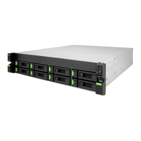
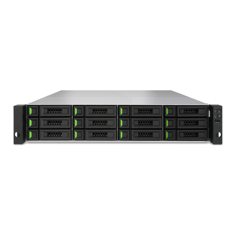
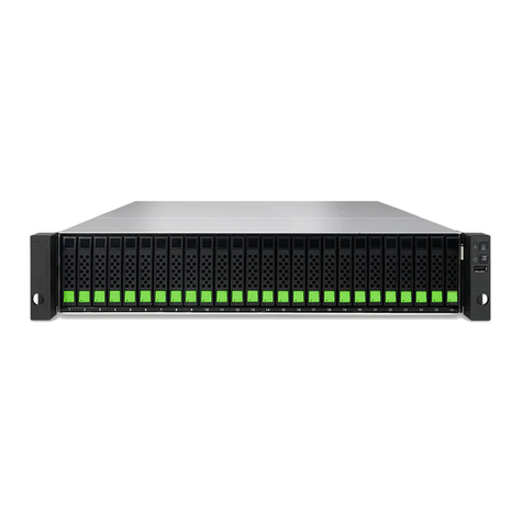
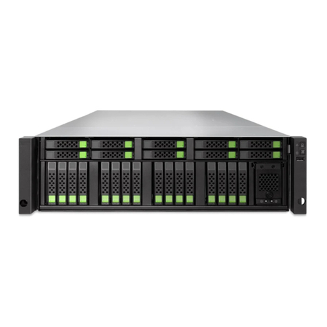
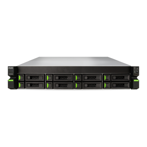
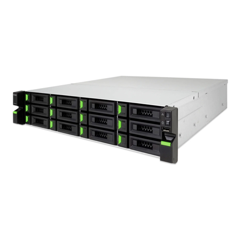
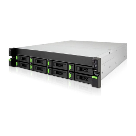
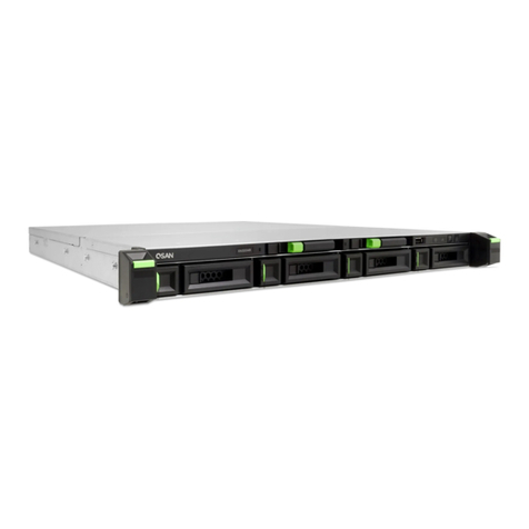
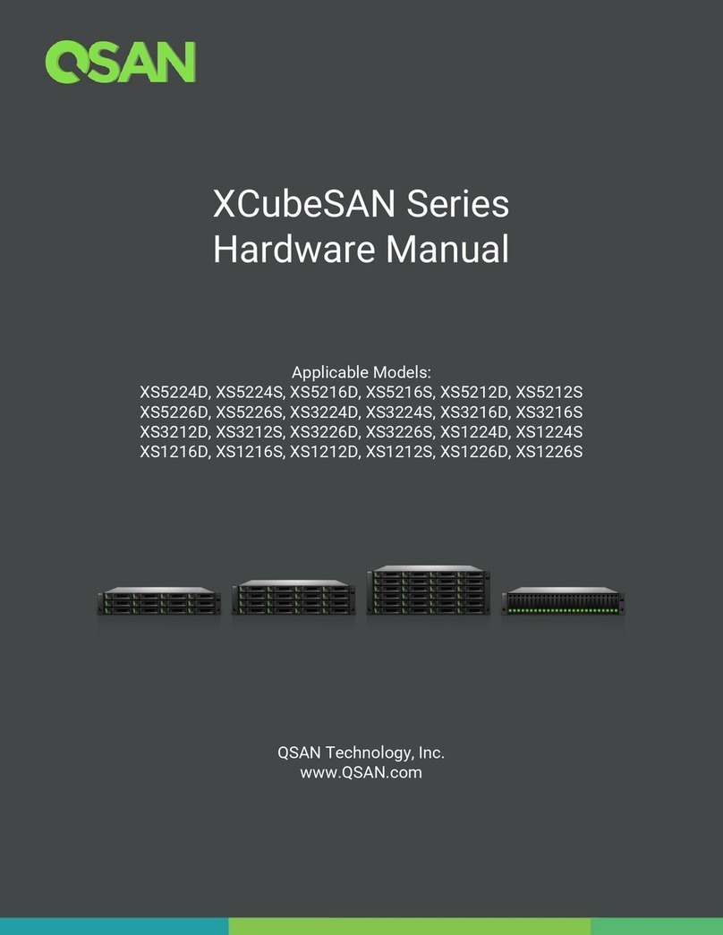
Figure 1-1 Form Factors of All XCubeSAN Series Models .............................................................. 2
Figure 2-1 System Controls and Indicators ...................................................................................... 8
Figure 2-2 LFF & SFF System Front Panel Components ................................................................. 9
Figure 2-3 Disk Drive Indicators of LFF & SFF Disk Drive Tray........................................................ 9
Figure 2-4 System Disk Drive Numbering for the XCubeDAS Series ............................................ 11
Figure 2-5 LFF & SFF Rear Panel Layout......................................................................................... 13
Figure 2-6 General View of the Controller Module......................................................................... 13
Figure 2-7 Components of the Controller Module ......................................................................... 14
Figure 2-8 Location of the Power Supply Unit in the LFF or SFF System..................................... 15
Figure 2-9 Components of the Power Supply Unit......................................................................... 16
Figure 2-10 Location of Each Fan Module Installed in the LFF or SFF System ............................. 17
Figure 2-11 Mechanical Components of the Fan Module ............................................................... 18
Figure 2-12 Seven-segment LED Display .......................................................................................... 19
Figure 3-1 Front Side Components of LFF & SFF Disk Drive Trays............................................... 21
Figure 3-2 Unlock and Open the Carrier Handle of a Disk Drive Tray (LFF) ................................. 22
Figure 3-3 Unlock and Open the Carrier Handle of a Disk Drive Tray (SFF) ................................. 22
Figure 3-4 Hold the Carrier Handle and Pull out the Disk Drive Tray (LFF) .................................. 23
Figure 3-5 Hold the Carrier Handle and Pull out the Disk Drive Tray (SFF).................................. 23
Figure 3-6 Align a Disk Drive & Install into a Tray (LFF-to-LFF)..................................................... 24
Figure 3-7 Align a Disk Drive & Install into a Tray (SFF-to-LFF) .................................................... 25
Figure 3-8 Align a Disk Drive & Install into a Tray (SFF-to-SFF) .................................................... 26
Figure 3-9 First Step of the Slide Rails Installation ........................................................................ 28
Figure 3-10 Second Step of the Slide Sails Installation................................................................... 28
Figure 3-11 Third Step of the Slide Rails Installation....................................................................... 29
Figure 3-12 Fourth Step of the Slide Sails Installation..................................................................... 30
Figure 3-13 Install a Tray into the System and Lock the Release Button Lock (LFF).................... 31
Figure 3-14 Install a Tray into the System and Lock the Release Button Lock (SFF).................... 31
Figure 3-15 One Server / One XCubeDAS / Dual Path ..................................................................... 32
Figure 3-16 One XCubeSAN / One XCubeDAS / Dual Path ............................................................. 32
Figure 3-17 Press the Power Button One Time to Power on the System....................................... 33
Figure 3-18 PSU Power Cord Connects ............................................................................................ 34
Figure 3-19 Power off the System by Power Button........................................................................ 35
Figure 3-20 Wake-on-SAS Technology.............................................................................................. 36
Figure 4-1 Cascade Topology: One Server / One XCubeDAS / Single Path ................................. 39
Figure 4-2 Cascade Topology: One Server / One XCubeDAS / Dual Path.................................... 40
Figure 4-3 Cascade Topology: One Server / Two XCubeDAS / Dual Path ................................... 41
Figure 4-4 Reverse Topology: One Server / Two XCubeDAS / Dual Path..................................... 42
