QTAC 70HPK User manual

Page | 2
Table of Contents
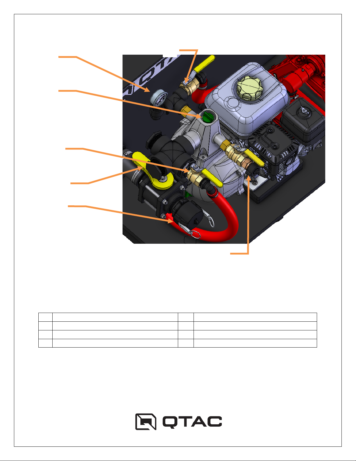
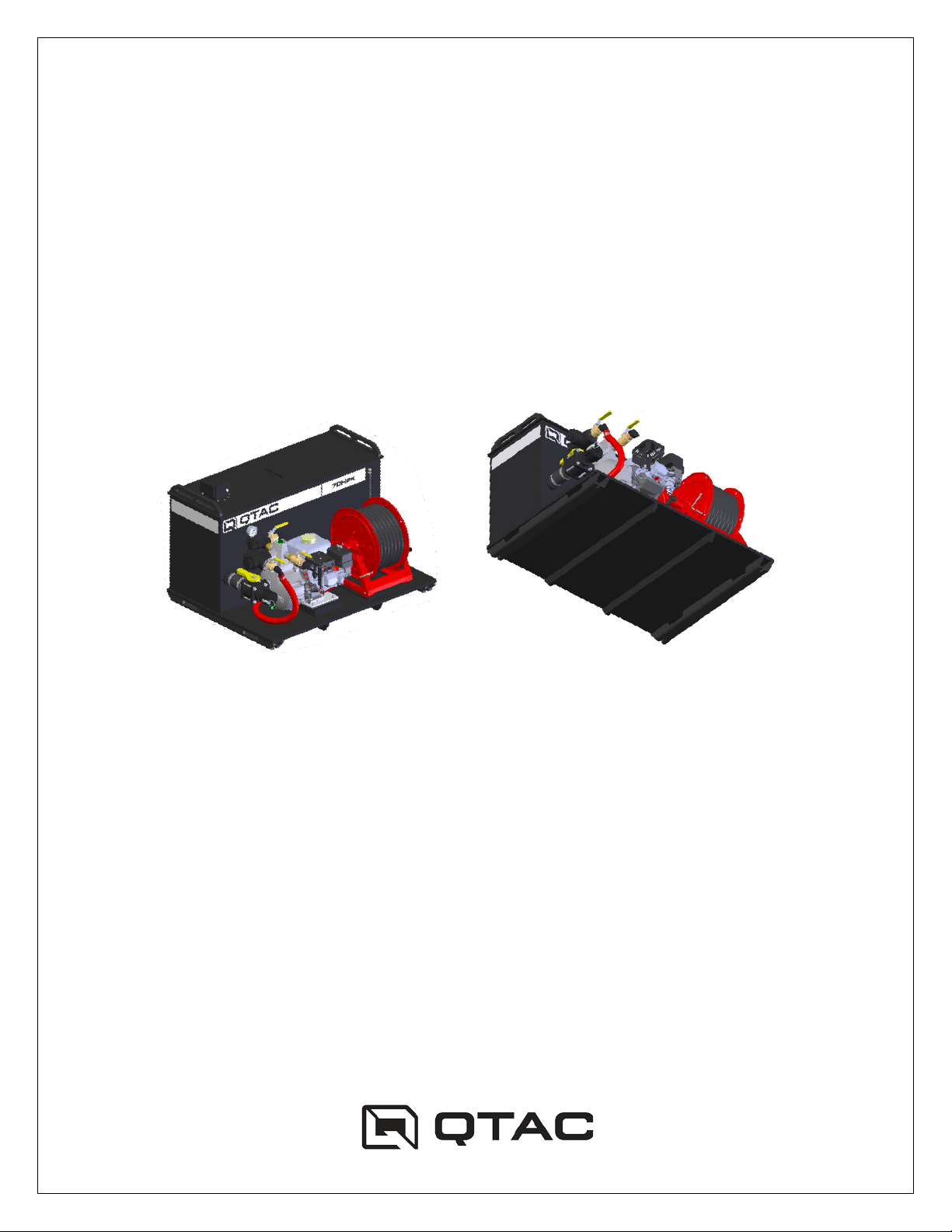
GETTING TO KNOW YOUR QTAC..................................................................................4
TRANSPORTING YOUR QTAC .......................................................................................7
Gross Vehicle Weight Rating.........................................................................................7
General QTAC Mounting and Fastening........................................................................7
Special Precautions for Carrying a QTAC on Ride-On ATVs or Side-By-Side UTVs ....8
OPERATING YOUR QTAC...............................................................................................9
Before Starting Up Your QTAC......................................................................................9
PUMP OPERATION..........................................................................................................9
Priming the Pump after an Extended Period of Use ......................................................9
Tank Fill Requirements:.................................................................................................9
Tank Fill Through the Fill Tower ..................................................................................10
Pumping Using the Tank Water Supply .......................................................................10
Starting the Engine ......................................................................................................11
DRAFT PROCEDURES..................................................................................................11
Drafting From an Auxiliary Water Source ....................................................................11
Connecting the Draft Hose ..........................................................................................11
Drafting to Fill the Water Tank .....................................................................................12
Pumping While Drafting From an Auxiliary Water Source ...........................................13
To Supply Water to the 1” NPSH Discharge................................................................14
STOPPING YOUR QTAC ...............................................................................................14
STORING YOUR QTAC .................................................................................................14
General Storage ..........................................................................................................14
SPECIAL QTAC OPERATION........................................................................................15
Using More Than Water in Your QTAC .......................................................................15
SERVICING YOUR QTAC ..............................................................................................15
Cleaning Your QTAC...................................................................................................15
Protecting Your QTAC.................................................................................................15
Routine QTAC Maintenance........................................................................................16
TROUBLESHOOTING YOUR QTAC..............................................................................16
The Pump Engine Will Not Start ..................................................................................16
The Pump Will Not Build Water Pressure ....................................................................16
Water Will Not Discharge From The Discharge Hose..................................................17

Page | 3
The Pump Engine Runs Erratically..............................................................................17
TECHNICAL SPECIFICATIONS.....................................................................................18
ADDITIONAL REFERENCES......................................................................................18
WARRANTY ...................................................................................................................19

Page | 4
GETTING TO KNOW YOUR QTAC
Figure 1 – Tank Components
1
Water Fill Tower
2 Discharge Hose Reel
3Grab Handle
4
Water Tank Sight Tube
5
Water Tank Drain
Port
6 Forklift Runners
2
5
4
1
3
6

Page | 5
Figure 2 - Pump Components
All Valves Shown in the Open Position
1
Pressure Gauge
5
Tank to Pump Valve
2
1” Pump to Tank Valve
6
Draft Hose Port
3
Pump Primer Port
7
1” NPSH Aux. Discharge Valve
4
1” Pump to Reel Valve
1
3
7
2
6
4
5

Page | 6
Figure 3 - Pump Engine Components
1
Fuel Fill
5
Pull Starter
2
Engine Throttle
6
Engine Switch
3
Carburetor Choke
7
Oil Fill (located on front as well)
4
Fuel Shut-off Valve
1
2
3
4
7
6
5

Page | 7
TRANSPORTING YOUR QTAC
Gross Vehicle Weight Rating
•Ensure that the gross vehicle weight rating (GVWR) of the QTAC carrying vehicle is
sufficient to support your QTAC unit with a full tank of water, plus any equipment,
fluids and personnel that you may wish to carry. Alternatively, you can reduce the
volume of water in your QTAC to maintain a GVWR under the limit of your vehicle.
General QTAC Mounting and Fastening
Figure 4 – Mounting Options
Ensure that your QTAC unit is secured to the carrying vehicle. Two main mounting
methods are available for your QTAC unit:
1. The preferred method of securing the QTAC to the bed of the vehicle is to mount
the QTAC at the forklift runner slots (Figure 4) located at the bottom of the water
tank on each side. The flanges have been machined to accept a variety of
mounting hardware options. Mounting hole locations are 43 7/8” across x 31 front
to rear.

Page | 8
2. If using straps to secure the QTAC to the bed of the vehicle, feeding the strap
around two grab rail posts, is preferred. This distributes the downward force over
a greater area. (Figure 4)
Securing the strap around a single grab rail post is acceptable. (Figure 4)
Securing the strap around the upper grab handle is not an approved method to
secure the QTAC (Figure 4). This will result in warping of the plastic handle, and
will eventually lead to handle failure.
For both mounting methods, ensure that the bottom of the QTAC (including the
mounting flanges) abuts a firm, flat surface or rack. Avoid significant leveraging of the
mounting flanges.
Special Precautions for Carrying a QTAC on Ride-On ATVs or Side-By-Side
UTVs
• Ensure that the area to which you are securing your QTAC is an approved
loading area for your ATV or UTV.
• Ensure that the weight of your QTAC does not exceed the maximum
recommended weight of the ATV or UTV loading area to which you are securing
your QTAC.
• Loading the bed of your ATV or UTV may affect steering response. Therefore,
the operator should spend some time operating the vehicle in a safe area (e.g.
wide and flat) once the QTAC has been properly secured and loaded to ensure
the vehicle operates in a safe manner. If the vehicle does not operate in a safe
manner, immediately recheck the GVWR calculations to ensure that the QTAC
unit is not overloading your vehicle. If the unsafe operation cannot be corrected,
do not carry your QTAC in this fashion.
• When carrying your QTAC unit on the rear rack of an ATV or in the bed of a UTV,
avoid steep side slopes. If an uphill must be traversed, it is recommended that

Page | 9
you back your ATV or UTV up the uphill to avoid the front wheels lifting on the
uphill.
OPERATING YOUR QTAC
Before Starting Up Your QTAC
• Always wear appropriate eye, ear, and body protection when operating your
QTAC unit.
• Ensure that your QTAC has sufficient water in the water tank prior to operation.
The water level can be checked by viewing the water tank site gauge located on
the side of the water tank (Figure 1) If the water tank is low on water, open the
water tank fill tower (Figure 1) and fill the water tank with water.
• Check the pump engine fuel (Figure 3) and oil levels (Figure 3) as needed, fill the
pump engine with fuel and oil as specified in the engine manual that came with
your QTAC. For more information, see the Pump Operation Manual and the
Engine Owner’s Manual.
PUMP OPERATION
Priming the Pump after an Extended Period of Use
The QTAC pumps are a self-priming pump, meaning they do not need to be primed
before every use. However, if the pump is being started after not being in use for more
than 12 hours, it may be necessary to add water to the primer port (Figure 2) to ensure
proper suction. To do so, simply pour water into the primer port until it is full, secure the
cap and start the engine.
Tank Fill Requirements:
MAX FILL PRESSURE: 100 PSI
MAX FILL RATE: 150 GPM

Page | 10
Tank Fill Through the Fill Tower
1. Open the fill tower and fill the tank. (Figure 1)
(For filling the tank by way of draft suction, see page 12)
Pumping Using the Tank Water Supply
1. Ensure that all valves are in the proper position.
a. The tank to pump valve should be open to pull water from the tank.
(Figure 2)
b. The 1” pump to tank should be cracked open slightly. (Figure)
c. The 1” NPSH Discharge should be fully closed. (Figure 2)
2. Start the engine (see next page)
3. Water can now be discharged through the reel line.
(To operate the 1” NPSH discharge, see page 13)
CAUTION! During pumping operations, the operator MUST either a) leave the
pump to tank valve open slightly to bypass water through the pump (reference
Figure 2), or b) leave the nozzle at least partially open at all times. Doing so
ensures that there is always water circulating through the pump to keep it from
overheating. Closing both the nozzle and the pump to tank line will result in
overheating the pump and pump failure.

Page | 11
Starting the Engine
1. Ensure that the engine has a sufficient amount of fuel in the gas tank. (Figure 3)
2. Ensure that the fuel shut-off valve is open. (Figure 3)
3. Turn the Engine switch to the on position. (Figure 3)
4. If the Honda engine is cold, apply the choke. (Figure 3)
5. Pull the hand starter cord until the engine starts. (Figure 3)
6. Apply throttle (Figure 3) and decrease the choke until it is no longer needed. The
output of the pump is regulated by how much throttle is applied (as well as the
shut-off at the nozzle, and the pump to tank return).
DRAFT PROCEDURES
Drafting From an Auxiliary Water Source
Your QTAC has the ability to draft water from an auxiliary water source. The operator
can either draft in order to fill the tank, or draft straight into the pump and out a discharge
line, bypassing the tank.
Connecting the Draft Hose
Remove the Camlock cap covering the draft hose port. Secure the draft hose Camlock
coupling to the draft hose port. (Figure 2)

Page | 12
Drafting to Fill the Water Tank
1. Close the tank to pump valve. (Figure 2) Ensure that the pump head is primed, as
described on Page 9.
2. Place the brass foot valve connected to the end of the draft hose into the water
source. For faster priming submerge and fill the draft hose. Make sure not to
place the foot valve in mud or dirt, as it will suck debris into the pump. Always
elevate the valve off the bottom of the water source to reduce the chances of
debris intake.
3. Connect the draft hose to the draft port.
4. Open the 1” Pump to Tank valve. (Figure 2)
5. Start the engine (see Page 11) and increase the throttle setting until you see
water entering the draft hose and being pulled into the pump head.
6. Monitor the water level using the water level sight tube. (Figure 1)
7. Once the tank is full, decrease the throttle setting and shut off the engine. Return
the valves to the positions needed in order to pull water from the tank and
continue pumping operations. (see Page 10)

Page | 13
Pumping While Drafting From an Auxiliary Water Source
1. Close the tank to pump valve (Figure 2) Ensure that the pump head is primed, as
described on Page 9.
2. Place the brass foot valve connected to the end of the draft hose into the water
source. For faster priming submerge and fill the draft hose. Make sure not to place
the foot valve in mud or dirt, as it will suck debris into the pump. Always elevate
the valve off the bottom of the water source to reduce the chances of debris
intake.
3. Open the hose reel nozzle slightly to ensure that water is allowed to run through
the pump after the engine is started.
4. Close the 1” Pump to Tank valve so that water does not enter the tank. (Figure 2)
5. Start the engine (see Page 11) and increase the throttle setting until you see
water entering the draft hose and being pulled into the pump head.
6. Use the hose reel discharge nozzle or 1” NPSH discharge line to carry out
suppression operations.

Page | 14
To Supply Water to the 1” NPSH Discharge
1. Connect your hose fitting to the 1” NPSH discharge outlet.
2. Lay out the hose, open the discharge valve slowly (Figure 2) to charge the line and
supply water to the nozzle.
STOPPING YOUR QTAC
1. If opened, gradually close the shut-off valve at the end of the discharge hose
2. Decrease the throttle on the pump engine to the idle position (Figure 3).
3. Set the engine switch to the “OFF” position (Figure 3)
STORING YOUR QTAC
General Storage
• Drain the fuel from the pump engine carburetor and fuel tank. See the Engine
Owner’s Manual for additional details.
• Drain any water from the water tank by opening all the valves, and the water tank
drain port (Figure 1)
• Drain the water from the pump by opening the pump drain port (Figure 2) See the
pump Instruction Manual for additional details.
NOTE: If your QTAC will be subjected to below freezing temperatures, ensure
that all water is drained from the water tank, pumping system, and hoses. Store
with all valves in the open position. If you would like to keep water in your QTAC
in below freezing temperatures, make sure to add an appropriate amount of RV
antifreeze to the water to prevent the formation of ice.

Page | 15
SPECIAL QTAC OPERATION
Using More Than Water in Your QTAC
If substances other than plain water have been used in the tank of your QTAC (e.g.
foam, pesticides, etc.), always clean and rinse the unit with clean water as soon as you
can after these chemicals have been used, until all traces of the chemicals have been
removed. Failure to flush the system in this manner can result in premature pump seal
failure, significant corrosion of the pump metal components, and build-up of chemical
byproducts in the tank and throughout the pumping system.
NOTE: Running substances other than plain water can cause significant foaming
to occur in the pumping system – if the pump has been run out of water with a
foaming agent in the tank, the pump will likely need to be primed on subsequent
water tank refills to remove the foam and to develop proper pressure.
Remove the cap from the pump primer port and fill the pump as needed (Figure
2) with clean water. Ensure that all the foam has been forced from the pump by
continually pouring water into the primer port until all foam has been displaced.
SERVICING YOUR QTAC
Cleaning Your QTAC
Your QTAC water tank is best cleaned with plain water. If additional cleaning power is
needed, a small amount of dish or car washing soap may be used. Avoid heavy
washing of the pump engine and surrounding area. Avoid the use of high pressure
spray on the water tank as the decals and rubber components may be damaged.
Protecting Your QTAC
Your QTAC is built of welded UV-stabilized copolymer red polypropylene plastic.
However, like any colored material, extended exposure to direct sunlight can eventually
fade the finish of the tank, hoses, hose reel and even the engine. To keep this from

Page | 16
happening, cover the QTAC if it is stored outside and in direct sunlight. Also, consider
using a UV inhibitor on the plastic and rubber parts after washing the system, such as
303 Aerospace UV Protectant.
Routine QTAC Maintenance
With the exception of the pump and pump engine, your QTAC requires no special
maintenance. For maintenance of the pump and pump engine, see the appropriate
manuals.
TROUBLESHOOTING YOUR QTAC
The Pump Engine Will Not Start
• Ensure that the engine switch is in the “ON” position.
• Ensure that the engine throttle is open slightly from the idle position.
• Adjust the choke. If the engine is cold, full choke will likely be needed.
• Ensure that fuel exists in the fuel tank, and the shut-off valve is on.
• For further troubleshooting information, see the Honda Owner’s Manual
The Pump Will Not Build Water Pressure
• Ensure that the pump engine is running and operating at a sufficient speed.
• Ensure that there is sufficient water in the water tank. There should be enough
water in the water tank so that the water level is visible in the water tank site
gauge (Figure 1)
• Unless the draft hose kit is in use, ensure that the Tank to Pump valve is open so
that the pump is drawing water from the water tank and not from the draft port
(Figure 2).
• Ensure that the pump drain port plug is properly tightened and sealed (Figure 2).

Page | 17
• Ensure that the pump is properly primed with water. Remove the cap from the
pump prime port and fill the pump as needed (Figure 2). If foaming mixtures have
been used in your QTAC recently, ensure that all the foam has been forced from
the pump by continually pouring water into the prime port until all the foam has
been displaced.
• Check the piping on the suction side of the pump to ensure that no air leaks are
present.
• For further troubleshooting information, see the pump Instruction Manual.
Water Will Not Discharge from The Discharge Hose
• Ensure that the pump engine is running and operating at a sufficient speed.
• Ensure that water pressure is available at the discharge hose port. This can be
checked by removing the hose connection at the discharge hose port.
• Check for hose kinking in the discharge hose.
• Ensure that the discharge hose shut-off valve is open.
• Ensure that the discharge hose nozzle is open.
The Pump Engine Runs Erratically
• Ensure that the engine has adequate fuel. Low fuel levels and operation over
rough and/or sloping terrain can cause the engine to momentarily run out of fuel.
• If the fuel has been stored for any length of time (and it has not been stabilized),
drain the fuel system and fill with fresh fuel.
• Proper engine performance is strongly dependent on a clean, lightly oiled air
filter. If the air filter is dirty or lacking oil, remove it from the air cleaner assembly,
clean with soapy warm water, rinse with fresh water and dry thoroughly. Once
dry, lightly saturate the element with clean engine oil and reassemble the air
cleaner assembly.

Page | 18
TECHNICAL SPECIFICATIONS
70HPK
Tank & Body
Fully-welded, top-grade Copolymer Polypropylene
MTECH PolyTough
TM
construction
Delivery Hose
3/4 inch x 50 feet industrial grade rubber (standard)
Delivery Nozzle
Brass ball valve shut-off with fully adjustable brass nozzle
Maximum Tank Capacity
70 US gal (318.2 L)
Pump Type
Koshin SERH-50Z self-priming, centrifugal (MAX 127 PSI,
132 GPM)
Engine Type
Honda GX200 4-stroke, overhead camshaft, single
Tank to Pump
2” NPT Gated Tank to Pump
Draft Hose Port
2” Camlock
ADDITIONAL REFERENCES
The following references are included with the shipment of your QTAC:
• Koshin SERH-50Z Instruction Manual (85HPK, 125HPK)
• Engine Owner’s Manual
We recommend that you read these manuals along with this QTAC Owner’s Manual –
Koshin SERH-50Z and engine manuals provide additional detail for the pump and pump
engine, respectively.

Page | 19
WARRANTY
GENERAL PROVISIONS - The warranty described below is provided by MTECH, Inc.
(hereinafter “MTECH”) to the original purchaser (hereinafter “Purchaser”) of new QTAC
fire suppression products (hereinafter “Product”) purchased from MTECH. Under this
warranty, MTECH will repair or replace, at its option, any covered part which is found to
be defective in material or workmanship during the applicable warranty term. Purchaser
shall provide MTECH with prompt written notice of the defect and allow reasonable time
for replacement or repair. Warranty services must be performed by MTECH, or an
MTECH designee, which will use only new or remanufactured parts or components
furnished by MTECH. Purchaser will be responsible for any service call and/or
transportation of Product to and from MTECH, or MTECH’s designee, for any premium
charged for overtime labor requested by Purchaser, and for any service and/or
maintenance not directly related to any defect covered under the warranties below.
WHAT IS WARRANTED - All parts of any Product are warranted for a period of 12
months, with the warranty term beginning on the date Product is delivered to Purchaser.
Note that some components may carry a manufacturer’s warranty – see the appropriate
component documentation for details. Warranty statements required by law covering
engine emission-related parts and components are found in the documentation
delivered with the Product.
WHAT IS NOT WARRANTED – MTECH IS NOT RESPONSIBLE FOR THE
FOLLOWING: (1) Used Products, (2) Any Product that has been altered or modified in
ways not approved by MTECH, (3) Any Product that is used in conjunction with non-
QTAC approved devices or equipment to perform tasks, (4) Any Product that is
mounted or secured in ways not approved by MTECH, (5) The vehicle or device used to
transport or house the Product, (6) Depreciation or damage caused by normal wear,

Page | 20
lack of reasonable and proper maintenance, failure to follow operating instructions,
misuse, lack of proper protection during storage, or accident, (7) Normal maintenance
parts, lubricants, and service, (8) Exposure of Product to non-approved contents and
environments, including, but not limited to, fuel, chemical agents, industrial effluents,
and extreme temperatures.
SECURING WARRANTY SERVICE – To secure warranty service, Purchaser must (1)
Report Product defect to MTECH and request repair within the applicable warranty
term, (2) Present evidence of the warranty start date, and (3) Make Product available to
MTECH within a reasonable period of time as agreed upon with MTECH.
LIMITATION OF IMPLIED WARRANTIES AND OTHER REMEDIES – To the extent
permitted by law, neither MTECH nor any company affiliated with it makes any
warranties, representations or promises as to the quality, performance or freedom from
defect of Product covered by this warranty. IMPLIED WARRANTIES OF
MERCHANTABILITY AND FITNESS FOR A PARTICULAR PURPOSE, TO THE
EXTENT APPLICABLE, SHALL BE LIMITED IN DURATION TO THE APPLICABLE
PERIOD OF WARRANTY SET FORTH IN THIS SECTION. PURCHASER’S ONLY
REMEDIES IN CONNECTION WITH THE BREACH OR PERFORMANCE OF ANY
WARRANTY ON THE PRODUCT ARE THOSE SET FORTH ON THIS PAGE. IN NO
EVENT WILL MTECH OR ANY COMPANY AFFILIATED WITH MTECH BE LIABLE
FOR INCIDENTAL OR CONSEQUENTIAL DAMAGES. (Note: Some states do not allow
limitations on how long an implied warranty lasts or the exclusion or limitation of
incidental or consequential damages so the above limitations and exclusions may not
apply to you.) This warranty gives you specific legal rights, and you may also have other
rights which vary from state to state.
Table of contents
Other QTAC Firefighting Equipment manuals