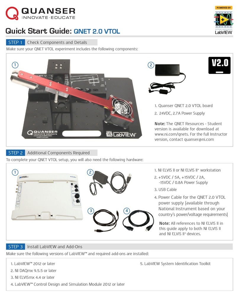
Quanser QNET 2.0 VTOL User manual

USER MANUAL
QNET 2.0 VTOL Board for NI ELVIS
Set Up and Configuration
CAPTIVATE. MOTIVATE. GRADUATE.
Solutions for teaching and research. Made in Canada.

© 2014 Quanser Inc., All rights reserved.
Quanser Inc.
119 Spy Court
Markham, Ontario
L3R 5H6, Canada
info@quanser.com
Phone: 1-905-940-3575
Fax: 1-905-940-3576
For more information on the solutions Quanser Inc. offers, please visit the web site at: http://www.quanser.com
This document and the software described in it are provided subject to a license agreement. Neither the software nor this document may be
used or copied except as specified under the terms of that license agreement. All rights are reserved and no part may be reproduced, stored in
a retrieval system or transmitted in any form or by any means, electronic, mechanical, photocopying, recording, or otherwise, without the prior
written permission of Quanser Inc.
FCC Notice This device complies with Part 15 of the FCC rules. Operation is subject to the following two conditions: (1) this device may not
cause harmful interference, and (2) this device must accept any interference received, including interference that may cause undesired operation.
Industry Canada Notice This Class A digital apparatus complies with Canadian ICES-003. Cet appareil numérique de la classe A est conforme
à la norme NMB-003 du Canada.
Japan VCCI Notice This is a Class A product based on the standard of the Voluntary Control Council for Interference (VCCI). If this
equipment is used in a domestic environment, radio interference may occur, in which case the user may be required to take corrective actions.
Korea Communications Comission (KCC) Notice This equipment is Industrial (Class A) electromagnetic wave suitability equipment and
seller or user should take notice of it, and this equipment is to be used in the places except for home.
이 기기는 업무용(A급)전자파적합기기로서 판
매자 또는 사용자는 이 점을 주의하시기 바라
며,가정외의 지역에서 사용하는 것을 목적으로
합니다.
Waste Electrical and Electronic Equipment (WEEE)
This symbol indicates that waste products must be disposed of separately from municipal household waste, according to Directive
2002/96/EC of the European Parliament and the Council on waste electrical and electronic equipment (WEEE). All products at the
end of their life cycle must be sent to a WEEE collection and recycling center. Proper WEEE disposal reduces the environmental
impact and the risk to human health due to potentially hazardous substances used in such equipment. Your cooperation in proper
WEEE disposal will contribute to the effective usage of natural resources. For information about the available collection and
recycling scheme in a particular country, go to ni.com/citizenship/weee.
This product meets the essential requirements of applicable European Directives as follows:
• 2006/95/EC; Low-Voltage Directive (safety)
• 2004/108/EC; Electromagnetic Compatibility Directive (EMC)
Caution: This is a Class A product. This product may cause radio interference in a domestic environment, in
which case the user may be required to take adequate measures.
QNET VTOL - User Manual 2

Contents
Safety Information 3
1 Introduction 5
2 System Hardware 6
2.1 System Schematic 6
2.2 Hardware Components 6
2.3 Environmental 9
2.4 System Parameters 9
3 QNET VTOL Assembly
Instructions 11
4 QNET VTOL and NI ELVIS II Setup 12
4.1 QNET VTOL Components 12
4.2 NI ELVIS II(+) Components 13
4.3 NI ELVIS II(+) Setup Procedure 13
5 Troubleshooting 16
5.1 General Software Issues 16
5.2 General Hardware Issues 16
6 Technical Support 18
QNET VTOL - User Manual v 1.0

Safety Information
The following symbols and definitions are interchangeably used throughout the User Manual:
Symbol Description
Caution: consult documenation for additional information
Direct Current
|On (Power) [on NI ELVIS II(+) unit]
Off (Power) [on NI ELVIS II(+) unit]
Table 0.1: Symbols
QNET VTOL - User Manual 4

1 Introduction
The Quanser QNET 2.0 Vertical Take-Off and Landing Board for NI ELVIS II, pictured in Figure 1.1, is a versatile
system designed to teach and demonstrate a variety of VTOL based experiments. The system is driven using a high
air flow DC fan attached to a solid aluminum link. A Single-ended rotary encoder is used to measure the angular
positon of the VTOL link.
Main QNET VTOL features:
• Compact and complete vertical take-off and landing system for NI ELVIS II(+)
• High air flow DC fan
• High-resolution optical encoder mounted on pivot
• Built-in current sense and digital tachometer
• Built-in PWM amplifier
Figure 1.1: Quanser QNET 2.0 Vertical Take-Off and Landing Board for NI ELVIS II
Caution
This equipment is designed to be used for educational and research purposes and is
not intended for use by the general public. The user is responsible to ensure that the
equipment will be used by technically qualified personnel only.
QNET VTOL - User Manual v 1.0

2 System Hardware
2.1 System Schematic
The QNET VTOL provides an integrated amplifier and a communication interface with the NI ELVIS II(+) for the
amplifier command and encoder ports. The interaction between the different system components on the QNET
VTOL is illustrated in Figure 2.1. The NI ELVIS II(+) is interfaced to the PC or laptop via USB link in the QNET VTOL
Interface. The NI ELVIS II(+) block reads the angular encoder inputs and commands the power amplifier that drives
the DC Motor.
Figure 2.1: Interaction between QNET VTOL components
The schematic given in Figure 2.2 illustrates the main QNET VTOL components and how they interact with the NI
ELVIS II(+).
Figure 2.2: Interaction between QNET VTOL components
2.2 Hardware Components
The main components comprising the QNET VTOL are labeled in Figure 2.3, and Figure 2.4 and are listed in
Table 2.1.
QNET VTOL - User Manual 6

ID# Description ID# Description
1 High-resolution encoder 8 Counter weight
2 VTOL Pivot 9 High air-flow DC fan
3+5 V,−15 V,+15 VLEDs 10 PCI connector
4 User and Status LEDs 11 VTOL metal chamber
524 VQNET power jack 12 5-pin Encoder connector
6 Fuse 13 5-pin Encoder connector
7 External Power indicator LED 14 8-pin Motor power connector
Table 2.1: QNET VTOL component nomenclature
Figure 2.3: General layout of QNET VTOL
QNET VTOL - User Manual v 1.0

Figure 2.4: Quanser QNET 2.0 Vertical Take-Off and Landing Board for NI ELVIS II components
2.2.1 High air flow DC fan
The QNET VTOL includes a 24 V,11,000 rpm high air flow fan attached to a solid aluminum frame link. The motor
specifications are given in Table 2.3.
The QNET VTOL incorporates a Sanyo Denki SanAce 60 G Series High air flow DC fan model
9G0624P4S001(0011). The complete specification sheet of the motor is included at:
db.sanyodenki.co.jp/product_db/cooling/dcfan/group_pdf/1309930942.pdf.
Caution
Exposed moving parts.
2.2.2 Encoder
The encoder used to measure the angular position of the QNET VTOL arm is a single-ended optical shaft encoder.
It outputs 2048 counts per revolution in quadrature mode (512 lines per revolution).
The encoder used to measure the angular position of the QNET VTOL arm is a US Digital E8P-512-118 single-ended
optical shaft encoder. The complete specification sheet of the E8P optical shaft encoder is given in E8P Data Sheet.
QNET VTOL - User Manual 8

2.2.3 Power Amplifier
The QNET VTOL circuit board includes a PWM voltage-controlled power amplifier capable to providing 2Apeak
current and 0.5Acontinuous current (based on the thermal current rating of the motor). The output voltage range
to the load is between 0Vand 10 V.
2.2.4 Status LED
The QNET VTOL is fitted with a variety of safety measures that use the Status LED for feedback, see Figure 2.3. In
particular, two digital enable lines (one high, one low) are used to ensure proper system configuration. The system
states are displayed as in Table 2.2. Here, a ∗indicates any state.
External Power (24 V) Enable+ Enable- Status LED Amplifier
0∗ ∗ Red Disabled
∗FALSE ∗Red Disabled
∗ ∗ TRUE Red Disabled
24 VTRUE FALSE Green Enabled
Table 2.2: Status LED states of the QNET VTOL
2.3 Environmental
The QNET VTOL is designed to function under the following environmental conditions:
• Standard rating
• Indoor use only
• Temperature 5◦Cto 40 ◦C.
• Altitude up to 2000m
• Maximum relative humidity of 80% up to 31◦C decreasing linearly to 50% relative humidity at 40◦C
• Pollution Degree 2
• Mains supply voltage fluctuations up to ±10% of the nominal voltage
• Maximum transient overvoltage 2500V
• Marked degree of protection to IEC 60529: Ordinary Equipment (IPX0)
2.4 System Parameters
Table 2.3 lists and characterizes the main parameters associated with the QNET VTOL.
QNET VTOL - User Manual v 1.0

Symbol Description Value
VTOL assembly
m1Counter-weight mass 258 g
m2Fan assembly mass 127 g
m3Link body mass 60 g
l1Length from pivot to center of counterweight 72.5mm
l2Length from pivot to center of fan 155 mm
l3Length from pivot to center of link body 7mm
B Estimated viscous damping of the pivot 0.002 Nm/(rad/s)
Pivot Encoder
Encoder line count 512 lines/rev
Encoder line count in quadrature 2048 lines/rev
Encoder resolution (in quadrature) 0.176 deg/count
Amplifier
Amplifier type PWM
Peak Current 2.5A
Continuous Current 0.5A
Output voltage ±24 Vwith 42 % duty cycle limit (±10 V)
Table 2.3: QNET VTOL System Parameters
QNET VTOL - User Manual 10

3 QNET VTOL Assembly
Instructions
Follow the instructions below to setup the QNET VTOL:
1. Remove the four thumbscrews that are used to attach the VTOL base to the QNET board for transport.
2. Rotate the support arm upright, and align the screw holes on the bottom of the support with the four holes
indicated on the bottom surface of the QNET board.
(a) Bring the support arm upright (b) Align the screw holes
Figure 3.1: Initial VTOL Setup Procedure
3. Tighten the four thumb screws to secure the VTOL assembly to the QNET board.
4. When fully assembled, the system should resemble Figure 1.1.
QNET VTOL - User Manual v 1.0

4 QNET VTOL and NI ELVIS II
Setup
The procedure to install a QNET VTOL module on the NI ELVIS II(+) is detailed in this section. The NI ELVIS II(+)
components used in the installation procedure are located and marked by an ID number in Figure 4.1, and described
in Table 4.1.
Caution
If the equipment is used in a manner not specified by the manufacturer, the protection
provided by the equipment may be impaired.
4.1 QNET VTOL Components
To setup the QNET VTOL system, you need the following components:
1. QNET VTOL PCB (shown in Figure 1.1)
2. VTOL module (shown in Figure 1.1)
3. QNET VTOL power supply (TRUMPower FRA072-S24-4, P/N: TRA72-S24-4G-509L, Output 24 VDC,3A)
Caution
Use only the power supply provided with with the QNET VTOL.
4. Power cable
5. Schurter 0034.3121,5mm ×20 mm,2.5A,250 VAC, time-lag fuse
QNET VTOL - User Manual 12

4.2 NI ELVIS II(+) Components
Figure 4.1: Components on NI ELVIS II(+)
ID# Description
1 NI ELVIS II(+)
2 Prototyping board power switch
3 Power LED
4 Ready LED
5 Power Cable for NI ELVIS II(+)
6 USB Connection between PC and NI ELVIS II(+)
Table 4.1: ELVIS II components
4.3 NI ELVIS II(+) Setup Procedure
Follow these instructions to setup a QNET VTOL board on an NI ELVIS II(+):
Caution
Do NOT make the following connections while power is supplied to the hardware!
QNET VTOL - User Manual v 1.0

Caution
The unit is provided with a grounded cord to be used with a properly grounded outlet
only, this is a safety feature, do not disable it.
1. Place the small opening on the front of the QNET VTOL board over the mounting bracket on the NI ELVIS
II(+).
2. Slide the PCI connector of the QNET VTOL module end into the female connector on the NI ELVIS II(+). Make
sure it is connected properly.
3. Connect the NI ELVIS II(+) power cable.
4. Connect the NI ELVIS II(+) USB cable to the PC.
5. Connect the supplied QNET power supply to the QNET VTOL power jack on the QNET VTOL module.
6. Power the NI ELVIS II(+) by turning ON the System Power Switch on the rear panel.
7. Turn ON the Prototyping Board Power switch, ID #2 shown in Figure 4.1.
8. The Power and Ready LEDs on the NI ELVIS II(+) unit should be lit as shown in Figure 4.2.
Figure 4.2: Ready and Power LEDs on NI ELVIS II(+)
9. Verify that the +15 V,−15 V,+5 Vand External Power LEDs on the QNET VTOL are lit green, and the Status
LED is red as shown in Figure 4.3. They indicate that the board has been properly connected to the NI ELVIS
II(+) unit and that the QNET VTOL currently does not communicate with a PC.
QNET VTOL - User Manual 14

(a) External Power LED should be ON
(b) LEDs on the right should be all green, Status LED
should be red
Figure 4.3: QNET VTOL LEDs
QNET VTOL - User Manual v 1.0

5 Troubleshooting
5.1 General Software Issues
Q1 When I try to open a QNET VTOL VI, it says there are some missing VIs and they have a CD or Sim in the
name?
The LabVIEW™ Control Design and Simulation Toolkit is not installed.
Q2 When I open a QNET VTOL VI a message prompts that a VI with ”ELVIS” in the name cannot be found?
The QNET VTOL VIs use the ELVISmx drivers. Make sure you install the contents of the NI ELVIS II(+) CD
before attempting to open any of the QNET VTOL VIs (available for download at www.ni.com).
5.2 General Hardware Issues
Q1 None of the LEDs on the QNET VTOL board are lit.
Make sure both the System Power switch, which is located on the back of the NI ELVIS II(+) unit, and the
Prototyping Board Power switch, which is situated on the top-right corner of the NI ELVIS II(+), are ON.
Q2 On the QNET VTOL board, the +15 V,−15 V,and +5 VLEDs are bright green but the External Power LED is
not lit.
Ensure the QNET VTOL power connector on the QNET VTOL board is connected with the supplied QNET
VTOL power cable. If the LED is still not lighting up, check the 2.5Afuse of the QNET VTOL next to the power
connector. If it is burnt, replace it with an identical fuse (Schurter 0034.3121,5mm ×20 mm,2.5A,250 VAC,
time-lag fuse). To remove the fuse, push and turn the fuse holder counter-clockwise.
Q3 At least one of the +15V,−15V,+5V and External Power LEDs on the QNET VTOL board is not lit.
• See Q2 above if only the External Power LED is not lit.
• If one or more of the +15V,−15V,and +5V LEDs is not lit then a ±15V or +5V fuse(s) on the Protection
Board of the NI ELVIS II(+) has been triggered. Similarly, if the External Power LED is still not lit after
connecting the QNET VTOL power, the Variable Power Supplies Fuses on the NI ELVIS II(+) Protection
Board have been triggered. See the Protection Board Fuses in the NI ELVIS II(+) User Manual.
Q4 The Ready LED on the elvis does not go on.
(a) Go through the elvis setup procedure outlined in the QNET VTOL Setup Guide
(b) Once completed, launch the Measurement & Automation Explorer software.
(c) As illustrated in Figure 5.1, expand the Devices and Interfaces and NI-DAQmx Devices items and select
the NI ELVIS II(+) device.
(d) As shown in Figure 5.1, click on the Reset Device button.
(e) Once successfully reset, click on the Self-Test button.
(f) If the test passed, reset the elvis (i.e. shut off the Prototyping Board switch and System Power switch
and turn them back on again). The Ready LED on the elvis should now be lit.
QNET VTOL - User Manual 16

Figure 5.1: Reseting and performing the self-test on the elvis
QNET VTOL - User Manual v 1.0

6 Technical Support
To obtain support from Quanser, go to www.quanser.com and click on the Tech Support link. Fill in the form with all
the requested software and hardware information as well as a description of the problem encountered. Also, make
sure your e-mail address and telephone number are included. Submit the form and a technical support person will
contact you.
QNET VTOL - User Manual 18

Solutions for teaching and research. Made in Canada.
Six QNET boards to teach introductory control topics using NI ELVIS
QNET 2.0 HVAC Board
teaches temperature (process) control
QNET Mechatronic Sensors Board
teaches functions of sensors
QNET 2.0 DC Motor Control Board
teaches fundamentals of DC motor control
QNET Myoelectric Board
teaches control using principles of
electromyography (EMG)
QNET 2.0 VTOL Board
teaches basic flight dynamics and control
QNET 2.0 Rotary Pendulum Board
teaches classic pendulum control
Quanser QNET add-on boards for the NI ELVIS platform teach introductory control topics in undergraduate labs cost-eectively.
All QNETs are oered with comprehensive, ABET*-aligned courseware that have been developed to enhance the student
learning experience.
To request a demonstration or quote, please email info@ni.com.
*ABET Inc., is the recognized accreditor for college and university programs in applied science, computing, engineering, and technology, providing leadership and quality assurance in
higher education for over 75 years.
©2014 Quanser Inc. All rights reserved. LabVIEW™ is a trademark of National Instruments.
Other manuals for QNET 2.0 VTOL
1
Table of contents
Other Quanser Computer Hardware manuals