Quantum Design ZillioX 6 User manual

Notice
Theinformationinthisdocumentissubjecttochange inordertoimprovereliability,design,
orfunctionwithoutpriornoticeand doesnotrepresentacommitmenton thepartofthis
company.Inno eventwillwebe liablefordirect,indirect,special,incidental,orconsequen-
tialdamagesarisingoutoftheuseorthepossibilityofsuchdamages.
All trademarksarethepropertyoftheirrespectiveowners.
Forfurtherinformation,pleasevisitourweb-site:“www.qdigrp.com”.
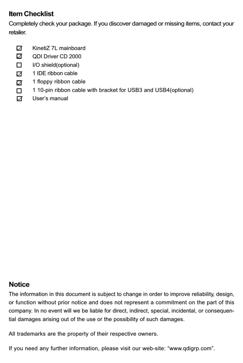
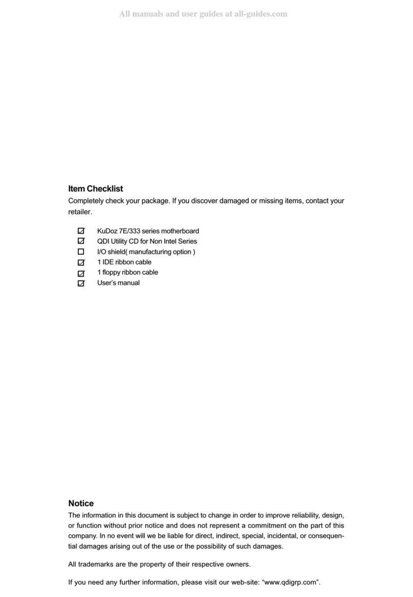
ItemChecklist
Completelycheck yourpackage.Ifyoudiscoverdamagedormissing items,contactyour
retailer.
ZillioX6motherboard
QDIMotherboardUtilityCD-ROM
RetentionModule
I/Oshield(manufacturingoption)
1IDEribboncable
1serialportribboncable(25-pinconnector)withbracket(manufacturingoption)
1floppyribboncable
User’smanual

Declarationofconformity
QUANTUMDESIGNS(HK)LTD.
5/FSomersetHouse,TaiKooPlace 979 KingsRoad,
QuarryBay,HongKong
declaresthatthe product
Pentium®IIMotherboard
ZillioX6
isinconformitywith
(referencetothespecificationunderwhichconformityisdeclaredin
accordancewith89/336 EEC-EMCDirective)
þEN55022 Limitsand methodsofmeasurementsofradiodisturbance
characteristics ofinformationtechnologyequipment
þEN50081-1GenericemissionstandardPart1:
Residential,commercialandlightindustry
þEN50082-1GenericimmunitystandardPart1:
Residential,commercialandlightindustry
EuropeanRepresentative:
QDICOMPUTER(UK)LTDQDICOMPUTER(SCANDINAVIA)A/S
QDISYSTEMHANDELGMBHQDICOMPUTER(NETHERLANDS)B.V.
QDICOMPUTER(FRANCE)SARLQDICOMPUTERHANDELSGMBH
QDICOMPUTER(ESPANA)S.A.QDICOMPUTER(SWEDEN)AB
Signature:Place/Date:HONGKONG/1998
PrintedName:AndersCheungPosition/Title:President
(ECconformitymarking)

Declaration ofconformity
TradeName:QDIComputer(U.S.A.)Inc.
ModelName:ZillioX6
ResponsibleParty:QDIComputer(U.S.A.)Inc.
Address:41456 ChristyStreet
Fremont,CA94538
Telephone:(510)668-4933
Facsimile:(510)668-4966
EquipmentClassification:FCC Class BSubassembly
TypeofProduct:AGPPentium®IIMotherboard
Manufacturer:QuantumDesigns(HK)Inc.
Address:5/F,SomersetHouse,TaiKoo Place
979 KingsRoad,QuarryBay,
HONGKONG
SupplementaryInformation:
Thisdevice complieswithPart15oftheFCCRules.Operationissubjectto
thefollowing twoconditions:(1)thisdevicemaynotcauseharmfulinterfer-
ence,and (2)thisdevicemustacceptanyinterference received,including
interferencethatmaycauseundesiredoperation.
Signature:Date:1998

I
1.Introduction ............................................................... 1
Overview.......................................................................................... 1
KeyFeatures..................................................................................... 1
2.InstallationInstructions............................................. 5
JumperSettings.................................................................... 5
ClockMultipleSelection...................................................................... 5
ClearCMOS....................................................................................... 6
Enable/Disableon-boardaudio........................................................... 6
Enable/Disableon-boardVGA............................................................ 7
Speaker-out/Line-outSelection........................................................... 7
Enablekeyboardpasswordand PS/2mousepower-onfunction......... 7
ExternalConnectors.............................................................. 8
PS/2KeyboardConnector,PS/2MouseConnector.............................. 8
USB1,USB2...................................................................................... 8
ParallelPortConnectorand SerialPortConnector................................ 9
Line-inJack,Microphone-inJackandSpeaker-out/Line-outJack ......... 9
AGPVGAConnector....................................................................... 10
PowerSupplyConnector&PowerSwitch........................................ 10
HardDiskLEDConnector................................................................. 10
ResetSwitch................................................................................... 11
SpeakerConnector.......................................................................... 11
PowerLEDConnector...................................................................... 11
Key-Lock Connector........................................................................ 11
Green LEDConnector...................................................................... 11
HardwareGreenConnector............................................................. 11
InfraredHeader............................................................................... 12
FanConnector................................................................................. 12
Wake-UpOnLAN............................................................................ 12
Wake-UpOnInternalModem............................................................. 13
ChassisSecurity............................................................................. 13
CDAudioConnector........................................................................ 13
VESA FeatureConnector................................................................. 14
ExpansionSlots&I/OPortsdescription............................................. 14
MemoryConfiguration................................................................ 14
CONTENTS
II
3.BIOSDescription.............................................................. 15
UtilitySupport........................................................................... 15
AWARD BIOSDescription........................................................ 17
EnteringSetup .....................................................................................17
LoadSetup Defaults.......................................................................... 17
StandardCMOSSetup ....................................................................... 17
BIOSFeaturesSetup ........................................................................ 20
ChipsetFeaturesSetup...................................................................... 22
PowerManagementSetup ................................................................. 24
PNP/PCIConfigurationSetup.............................................................. 27
IntegratedPeripherals........................................................................ 30
SystemMonitorSetup ....................................................................... 30
PasswordSetting .............................................................................. 31
IDEHDD AutoDetection...................................................................... 32
BootwithBIOSdefaults..................................................................... 33
4.ATIRageIIC/ProAGPGraphics Description ............... 35
Features..............................................................................................35
SystemRequirements..............................................................35
InstallationofATIRageIICDisplayDriversforWindows95/98/NT..........36
Configuring Windows95 Driver............................................................38
Configuring WindowsNT4.0Driver......................................................40
5.CreativeAudioDescription ............................................ 41
Features..............................................................................................41
CreativeSoftwareInstallation ....................................................42
InstallationofWindows95 driver..........................................................42
InstallingDriverinDOS/Windows3.1X..................................................43
InstallationofWindowsNT4.0Driver...................................................43
Enabling/Disablingthe Creative3DStereo EnhancementEffect ..............44
SoftwareWavetableSynthesis............................................................45
AppendixAQDIMotherboardUtilityCD-ROM...................... 47
AppendixBProcessorInstallationProcedures.................... 49
AppendixCBootLogo ........................................................ 52
CONTENTS

ManualforZillioX6
Chapter1
Introduction
Chapter1
Introduction
Overview
TheZillioX6isahighlyintegrated,cost-effective,microATXmotherboardwhichiscentered
ontheIntel®
440ZXAGPset.Itprovides66MHzand100MHzsystembussupportforIntel
Pentium®
IIandCeleronTMprocessors.Both66MHz/100MHzSDRAMsand66MHzEDODIMMs
aresupported.It alsoprovidesadvancedfeaturessuchaswake-up onLAN,wake-up on
internal/externalmodemandkeyboardpasswordpower-on function.ManageEasy,our
managementapplicationissupplied toenableremotemonitoringandconfiguringofthe
system.TogetherwithitsintegratedCreativeCT2511SBTaudioand integratedATIRage
IIC(orATIRagePro)AGPvideo,yougetastate-of-the-artcorporatesystem.
Key Features
Formfactor
lmicroATXformfactorof244mmx210mm.
lProvidesbackwardcompatibilitywithstandardATX2.01 chassisforeasy
integration.
Microprocessor
lSupportsallIntelPentium®
IIprocessorsat233/266/300/333MHz
with66MHzbusspeedand350/400/450MHzwith100MHzbusspeed.
lSupportsIntel®CeleronTMprocessorsat266/300/333MHzwith66MHzbus
speed.
lSupports66MHzand 100MHzhostbusspeed.
lCPUcorefrequency=Busspeedx3,x3.5,x4,x4.5,x5,x5.5.
lCPUcorevoltagecanbeselectedfrom1.3Vto3.5Vautomaticallythrough
on-boardswitching voltageregulatorwithVID(VoltageID).
Chipset
lIntel®
440ZXAGPset:82443ZX,82371EB(PIIX4E).
Systemmemory
lProvidestwo168 pin3.3VunbufferedDIMM sockets.
lSupportsboth66MHz/100MHzSDRAMsand66MHzEDODIMMs.
lMinimummemorysizeis8MB,Maximummemorysizeis512MB.
1
Chapter1

ManualforZillioX6
On-boardIDE
l
SupportstwoPCIPIOandBusMasterIDEports.
l
TwofastIDEinterfacessupporting fourIDEdevicesincludingIDEharddisks and
CD-ROMdrives.
l
SupportsuptoPIOmode4timing.
l
Supports“UltraDMA/33”SynchronousDMAmode,transferringupto33Mbytes/sec.
l
Integrated16x32bitbufferforIDEPCIBurstTransfers.
On-boardI/O
l
UseWinbondW83977EFsuperI/Ochip.
l
Onefloppyportsupporting up totwo3.5”or5.25”floppydriveswith360K/720K/
1.2M/1.44M/2.88Mformat.
l
Twohighspeed 16550fastcompatibleUARTs(COM1/COM2/COM3/COM4
selective)with16-bytesend/receiveFIFOs.
l
OneenabledparallelportattheI/Oaddress 378H/278H/3BCH withadditional
bi-directionI/Ocapabilityand multi-modeasSPP/EPP/ECP(IEEE1284compliant).
l
Circuitprotectionprovided,preventing damagestotheparallelportwhena
connectedprinterispoweredup oroperatesatahighervoltage.
l
SupportsLS-120 floppydisk drive.
l
AllI/Oportscanbeenabled/disabledintheBIOSsetup.
On-boardaudio
l
Based ontheCreativeViBRA™16XV CT2511sound chip.
l
CompatiblewithSoundBlaster™,SoundBlasterPro™andWindowsSound
System™.
l
SupportsFMMusicSynthesizerand Software-basedWavetableSynthesizer.
l
Stereo EnhancementSupport.
l
Provideson-boardLine-inJack,Microphone-inJack,Speaker-out/Line-outJack
andMIDI/JoystickConnector.
On-boardAGP
l
BasedontheATIRageIIC(orATIRagePro)AGPgraphicscontroller.
l
Integrated3D,2Dand video acceleratorswithpaletteDACand quadrupleclock
synthesizer.
l
2MB/4MBSGRAMonboardandaSO-DIMMsocketforextensionuse
(manufacturing option).
l
Supportsamaximumresolutionof1600x1200 at76Hz.
Introduction
2

ManualforZillioX6
AdvancedFeatures
l ProvidesTrend ChipAwayVirus®OnGuard.
l Provideson-boardPS/2mouseandPS/2keyboardports.
l ProvidestwoUSB ports.
l Providesinfraredinterface.
l SupportsWindows95/98softwarepower-down.
l Supportsexternalmodemringpower-on.
l Supportswake-up onLANandwake-up oninternalmodem.
l Supportsautofanoffwhenthesystementerssuspend mode.
l On-boardWinbond W83782Dsupportssystemmonitoring (monitorsthe CPU&
systemtemperature,systemvoltages,chassisintrusionand fanspeed).
l ProvidesmanagementapplicationsuchasManageEasyand LDCM(LANDesk®
ClientManager).(manufacturingoption).
l Supportskeyboardpasswordand PS/2mousepower-onfunction.
l Systemstatusresumes(selectable)afterACpowersupplyfailure.
BIOS
lLicensed advancedAWARDBIOS,supportsDIPflashROMwith2MB
memorysize,plug and playready.
lSupportsIDECD-ROMorSCSIbootup.
Greenfunction
lSupportsACPI(AdvancedConfigurationand PowerInterface)andODPM(OS
DirectedPowerManagement).
lSupportsthree greenmodes:Doze,StandbyandSuspend.
lTheGreenLEDwill flashwhenthesystemisinthegreenstatus.
Expansionslots
l 1ISAslotand 2PCIslots.
3
Chapter1

ManualforZillioX6
--Thispage isintentionallyleftblank--
4

ManualforZillioX6
Chapter2
Installation Instructions
Chapter2
Installation Instructions
ThissectioncoversJumperSettings,ExternalConnectorsand MemoryConfiguration.Re-
fertothemotherboardlayoutchartforlocationsofall the jumpers,externalconnectors,
slotsand I/Oports.Furthermore,thissectionlistsall necessaryconnectorpinassignments
foryourreference.Theparticularstateofthe jumpers,connectorsand portsareillustrated
inthefollowing figures.Beforesettingthejumpersorinserting theseconnectors,please
payattentiontothedirections.
JumperSettings
Jumpersettingsarelocatedonthemotherboard.Pin1ofall jumpersarelocated on theside
withathickwhiteline(Pin1),referringtothemotherboardsilkscreen.Jumpers
withtwopinswill beshowngraphicallyasforcloseand foropen.Jump-
erswiththree pinswill beshownastorepresentpin1&pin2connectedand
torepresentpin2 &pin3 connected.
ClockMultipleSelection (JX4,JX3,JX2,JX1)
ThesejumperssetthefrequencyratiobetweentheInternalfrequencyoftheCPUand the
externalfrequency (namelytheBusClock).Thesystemcandetermine theexternalfre-
quency(BusClock)oftheCPUautomatically.TheBusClockmultipliedbytheClockMultiple
equalsthe CPU’sfrequency.
Chapter2
Besuretounplug theACpowersupplybeforeadding orremoving expansion
cardsorothersystemperipherals,otherwiseyourmotherboardandexpansion
cardsmightbeseverelydamaged.
5
JX4JX3JX2JX1
x3.0JX4JX3JX2JX1
x3.5JX4JX3JX2JX1
x4.0
JX4JX3JX2JX1
x4.5JX4JX3JX2JX1
x5.0JX4JX3JX2JX1
x5.5

ManualforZillioX6
23366 3.5Close
26666
66
66
300
333
4.0
4.5
5.0
Close
Close
Close
CloseClose
CloseClose
Close
Open
Open
Open
Open
Open
Open
Open
100
100
100
350
400
450
3.5
4.0
4.5
Close
Close
Close
CloseClose
CloseClose
Open
Open
OpenOpen
Open
5001005.0CloseCloseOpenOpen
InstallationInstructions
Enableon-boardaudio
Disableon-boardaudio
6
Carefullysetthe Clock Multiplebyreferring tothe CPUlist.
CPUFreq.SCRatioJX1JX2JX3JX4
Model(MHz)(MHz)
Intel
PentiumII
(orCeleronTM)
ClearCMOS(JCC)
If you wanttoclearCMOS,unplugthe ACpowersupplyfirst,closeJCC(pin1&pin2)once,
setJCCback tonormalstatuswithpin2 &pin3 connected,then poweronthesystem.
Enable/Disableon-boardaudio(JP7)
Ifyouwanttousetheon-boardaudio,closeJP7(default).Otherwise,setJP7opento
disabletheon-boardaudio.
JP7
JP7
ClearCMOS:
(UnplugtheACpowersupply)
Normalstatus:123
123
JCC
JCC

ManualforZillioX6
Enable/Disableon-boardVGA(JP10)
If you wanttouseon-boardVGA,closeJP10(default).Otherwise,setJP10openfor
disabling theon-boardVGA.
Speaker-out/Line-outSelection(JP8,JP9)
Ifyouwanttosetthe Speaker-out/Line-outJack asSpeakerout, setJP8&JP9withpin1&
pin2 closed(default).Otherwise,setJP8&JP9withpin2 &pin3closedforLineout.
EnablekeyboardpasswordandPS/2mousepower-on function
Themotherboardprovidesadvancedkeyboardpasswordand PS/2mousepower-on
function.Tousethesefunctions,setJP3withpin1&pin2 closed(default).Otherwise,set
JP3withpin2 &pin3 closedfordisabling thesetwofunctions.
Inordertoimplementthesefunctions,youneed toset“POWERONFunction”asPass-
word/MouseLeft/Mouse Rightaccordinglyinthe“INTEGRATEDPERIPHERALS”
sectionofCMOSSetup.IfsetasPassword,thekeyboard
Enableon-boardVGA
Disableon-boardVGA
JP10
JP10
7
Chapter2
Speakerout
Line out
321
321
JP9
JP8
JP9
JP8
Disable
Enable321
321
JP3
JP3

ManualforZillioX6
power-on passwordmustbesetalso.Thensaveandexit, poweroffthe system.The
systemcanbepoweredup byentering thecorrectpasswordfromthekeyboardordouble
clicking thePS/2mousebutton(Left/Right),according toyourprevioussettingsinCMOS
Setup.RefertoBIOSdescriptionfordetailedinformation.
Note:
1. Ifwantingtouse keyboardorPS/2mousetopowerup thesystem,
make sure5VSBlineofthepowersupplyiscapableofdelivering
enoughcurrent(eg.200mA)foralldevices connectedtothekeyboard
port,oryouwillbeunabletopowerup thesystembyusingthekeyboard
orPS/2mouse.
2.Thepowerbutton’spower-onfunctionisdisabledwhenkeyboard
passwordpower-onfunctionisenabled.
3.APS/2mouse isrequiredtopowerupthesystem,ratherthanaserial
portmouse.
4.Ifyou setJP3withpin2&pin3closed,youshouldset“POWERONFunc
tion”asBUTTONONLY,donotsetitasPassword/MouseLeft/Mouse
Right,orthiswill preventyou frompoweringupthesystem.
5. Ifyou encountertheabove problems(thesystemcan’tbepowered
up),oryouforgotthepassword,clearCMOS,resetthejumperand BIOS
option.
ExternalConnectors
PS/2KeyboardConnector,PS/2MouseConnector
PS/2keyboardconnectorisfortheusageofPS/2keyboard.Ifusing astandardATsize
keyboard,anadaptershouldbeusedtofitthisconnector.PS/2mouseconnectorisfor
theusageofPS/2mouse.
USB1,USB2
TwoUSB portsareavailableforconnecting USB devices.
8
InstallationInstructions
PS/2MouseConnector
PS/2KeyboardConnector
Bottom:USB2
Top:USB1

ManualforZillioX6
ParallelPortConnectorand SerialPortConnector(UART1,UART2)
Theparallelportconnectorcanbeconnectedtoaparalleldevicesuchasaprinter,while
theserialportconnectorscanbeconnectedtoserialportdevicessuchasaserialport
mouse.Youcan enable/disablethemandchoosetheIRQorI/Oaddress in“INTEGRATED
PERIPHERALS”fromAWARDBIOSSETUP.
TheserialportUART2isnotlocatedontheback panel.Therefore,weprovidea25-pin
ribboncablewithbracketforUART2port. (manufacturing option)
Line-inJack,Microphone-inJack andSpeaker-out/Line-outJack
TheLine-injackcanbe connectedtodevicessuchasacassetteorMinidiscplayerfor
playbackorrecording.TheMicrophone-injackcan beconnectedtoamicrophoneforvoice
input. TheSpeaker-out/Line-outjackisdeterminedbythejumpersJP8&JP9(refertoJumper
Settingsfordetails).IfsetasLine-out,itallowsyou tobypassthebuilt-inamplifierto
connectpowered speakersoranexternalamplifierforaudiooutput. IfsetasSpeaker-out,
itallowsyoutoconnectspeakersorheadphonesforaudiooutputfromtheinternalamplifier.
MIDI/Joystick connectorallowsyoutoconnectagamejoystick oraMIDIdevice.
1
9
Chapter2
ParallelPort
SerialPort(UART1)
MIDI/Joystick
speakerout/line outlineinMicrophonein

ManualforZillioX6
AGPVGAConnector
Thisconnectorshouldbeconnectedtoastandardmonitorifthe on-boardAGPVGAis
used(refertoJumperSettingsfordetailedinformationon enabling/disabling AGP).
PowerSupplyConnector(J10,J11)&PowerSwitch(POWER)
ATX/SFXpowersupplycanbothbeusedonthissystem.Besuretoconnectthepower
supplyplugtoconnectorJ10 inthe properorientation.The powerswitch(POWER)should
beconnected toamomentaryswitch.Whenpowering up yoursystem,firstturnonthe
mechanicalswitchofthepowersupply(ifoneisprovided),thenpushoncethebuttonof
thepowerswitch.Whenpoweringoff the system,you needn’tturnoffthemechanical
switch,justpushonce*the buttonofthepowerswitch.
J11isanoptional6-pinpowerconnectorusedforthepowersupplywhichhasanidentical
connector.The pinassignmentandthelocationoftheconnectorsareasshownbelow:
Note:*Ifyouchange“soft-off byPWR-BTTN”fromdefault“Instant-off”to
“Delay4Secs”inBIOSSetup(POWERMANAGEMENTSETUP),thepowerbutton
shouldbepressedformorethan4secondsbeforethesystempowersdown.
**Thisoptionalsignal(-5V)isnotavailableintheSFXpowersupply.
HardDiskLEDConnector(HDLED)
Theconnectorconnectstothecase’sIDEindicatorLEDindicating theactivitystatusof
IDEharddisk.
10
InstallationInstructions
AGPVGAConnector
POWER
PowerSupplyConnector(J10)
5V5V-5VGNDGNDGNDPSON
GND-12V3.3V
12V5VSBPS-OKGND5VGND5VGND3.3V3.3V
1
20
**
NC
NC
OptionalPower
Connector(J11)
Fanmonitoring
Fancontrol
3.3Vsense
NC

ManualforZillioX6
ResetSwitch(RESET)
Theconnectorconnectstothe case’sresetswitch.Presstheswitchonce,the system
resets.
SpeakerConnector(SPEAKER)
Theconnectorcanbeconnectedtothespeakeronthecase.
PowerLEDConnector(PWRLED)
ThepowerLEDhasthree status.WhennoACpowersupplyispresent,theLEDisoff.
Whenthesystemisinsoftpower-downstatus,theLEDglowsdimly.Whenthesystemis
powered up,theLEDison.
Key-LockConnector(KEY_L)
Theconnectorcan beconnectedtothekeyboardlock switchonthecaseforlockingthe
keyboard.
GreenLEDConnector(GRNLED)
The GreenLEDhasfourstatus.WhennoACpowersupplyispresent,theLEDisoff.When
the systemisinpower-offstatus,the LEDisglowsdimly.Whenthe systemispoweredup,
theLEDison.Whenthe systementersgreenmode,theLEDwillflash.
HardwareGreenConnector(SLEEP)
Pushoncetheswitchconnectedtothisconnector,thesystementerssuspend
mode.
11
Chapter2
LED+
LED-
GND
RESET
SPKDATA
NC
GND
VCC
GND
POWER
LED+
LED-
LED-
KEYLOCK
GND
LED+
LED-
LED-
SLEEP
GND
HD_LED
RESET
POWER
KEY_L
SPEAKER
PWR_LED
GREEN_LED
SLEEP

ManualforZillioX6
Wake-UpOnLAN(WOL)
Through Wake-up OnLANfunction,awakeeventoccuringfromnetworkcanwakeupthe
system.Ifthisfunctionistobeused,pleasebesureanATX2.01 powersupplyofwhich
5VSB lineiscapableofdelivering720mA,andaLANadapterwhichsupportsthisfunction
areused.Then connectthisheadertotherelevantconnectoronthe LANadapter,set
“WakeUpOnLAN”asEnabledfromthe “POWERMANAGEMENTSETUP”section ofthe
BIOS.Save&exit, thenboottheoperating systemoncetomakesurethisfunction takes
effect.
InfraredHeader(IRDA)
Thisconnectorsupportswireless transmittingand receiving.Youmustset“SerialPort2
Mode”toIrDAorASKIRandconfigurethesettingsinthe“INTEGRATEDPERIPHERALS”
sectionoftheBIOS.
FanConnector(CPUFAN,CHSFAN)
Thesetwofansarecontrollable.Theywillbeautomaticallyturnedoffafterthe system
enterssuspendmode.Youcan alsochoosenottoturntheCPUFANoffbysetting“CPUFAN
offInSuspend”asDisabledinthe“POWERMANAGEMENTSETUP”sectionoftheBIOS.
+5Vstandby
GND
Signalforwakingup (activehigh)
WOL
12
InstallationInstructions
IrDA
VCC
NCIRRX
GND
IRTXVCC
FANGND(Controllable)
+12V
SENSE
CPUFAN
CHSFAN
FANGND
+12VSENSE

ManualforZillioX6
Chapter2
13
Wake-UpOnInternalModem(WOM)
Throughthe Wake-UpOnInternalModemfunction,thesystemwhichisinpower-offstatus
canbe poweredup byaring signalreceivedfromtheinternalmodem.Ifthisfunction isto
beused,pleasebe sureaninternalmodemcardwhichsupportsthisfunction isused.Then
connectthisheadertotherelevantconnectoronthemodemcard,set“ResumebyRing”to
Enabled fromthe“POWERMANAGEMENTSETUP”section ofthe BIOS.Save&exit,then
boottheoperating systemoncetomakesurethisfunctiontakeseffect.
ChassisSecurity(CHSSEC)
Theconnectorcanbeconnectedtothechassissecurityswitchonthecase.Whenusing
QDI’sManageEasysoftware,thesystemcan detectthe statusofthe chassis.Fordetailed
information,refertotheManageEasymanuallocatedinthepath\DocfromtheQDI
motherboardutilityCD.
CD AudioConnector(CDLIN,MITSU)
TheCD AudioConnectorcanbeconnected toaCD-ROMdrivethroughaCD audiocable.
WiththespeakersconnectedtoSpeaker-out/Line-outjack,audiocanbeheardfromthe
CD-ROMdrive.
+5Vstandby
GND
Signalforwakingup (activelow)
WOM
CHSSEC
GND
Indicatesignal
MITSU CDLIN(SONY)
CD RightChannel
GND
CD Left Channel
GND
GND
GND
CD RightChannel
CD Left Channel

ManualforZillioX6
Installation Instruction
VESAFeatureConnector(VFC)
ExpansionSlots&I/O Portsdescription
Slot/PortDescription
ISAISAslot
PCI1FirstPCIslot
PCI2Second PCIslot
IDE1PrimaryIDEport
IDE2SecondaryIDEport
FLOPPYFloppyDrivePort
MemoryConfiguration
Thismotherboardprovidestwo168 pin3.3Vun-bufferedDIMM socketstosupporta
flexiblememorysizeranging from8MB/256MBforSDRAMorfrom8MB/512MBforEDO
memory.Both66MHz/100MHzSDRAMand66MHzEDODIMMsaresupported.The
following setofrulesallowsoptimumconfigurations.
Rules forpopulatinga440ZXmemoryarray:
lEDO/SDRAMDIMMscannotbeusedon the samesystem,itisadvisedyou
useonlyone kind ofDIMM.
lProcessorswith100MHzfront-sidebusshouldbepairedonlywith100MHzSDRAM.
Processorswith66MHzfront-sidebuscanbepairedwitheither66MHzSDRAM/EDO
or100MHzSDRAM.
lNoRegisteredDIMMsupport.
lTheDRAMTiming register,whichprovidestheDRAMspeedgradecontrolforthe
entirememoryarray,mustbeprogrammedtousethe timing oftheslowestDRAMs
installed.
lPossibleEDODIMMmemorysizesare8MB,16MB,32MB,64MB,128MB,256MBin
eachDIMMsocket.
lPossibleSDRAMDIMMmemorysizesare8MB,16MB,32MB,64MB,128MBineach
DIMMsocket.
14
1

ManualforZillioX6
Chapter3
BIOSDescription
Chapter3
BIOSDescription
UtilitySupport:
FLASH.EXE
Thisisaflashmemorywrite/readutilityusedforthepurposeofupdating yourBIOS
whennecessary.Beforedoingso,pleasenote:
lWestronglyrecommend youonlyupgradeBIOSwhenencountering problems.
lBeforeupgradingyourBIOS,reviewthedescription belowtoavoidmaking
mistakes,resultinginadestroyedBIOSandanon-workingsystem.
When youareencounteringproblems,forexample,youfind yoursystemdoesn’tsupport
the newCPUwhichisreleased afterourcurrentmotherboard,youmaythereforeupdate
theBIOS.
Followthestepsexactlyforasuccessfulupgrade.
1.Createabootablesystemfloppydiskettebytyping FormatA:/sfromtheDOSprompt
underDOS6.xxorWindows9xenvironment.
2.CopyFLASH.EXEfromthedirectory\UtilityontheQDIMotherboardUtilityCDonto
yournewbootablediskette.
3.Downloadtheupdated BIOSfilefromtheWebsite(http://www.qdigrp.com).Please
besuretodownloadthesuitableBIOSfileforyourmotherboard.
4.Uncompress thefiledownload,copytheBIOSfile(xx.bin)ontothebootablediskette,
and writedownthechecksumofthisBIOSwhichisincludedinreadmefile.
5.Rebootthesystemfromthebootablediskettewhichyouhavecreated.
6.Then run the FLASHutilityattheA:\prompt. During theprocess,thesystemwill
prompt:‘DoyouwanttosavetheBIOS(Y/N)’.Ifyoutype ‘Y’,the systemwillprompt
fortheBIOSname.Thesystemwill alsodisplaythechecksumwhichshouldbe
exactlythesameasthechecksumyoucopiedfromthe readmefile.Don’tturnoff
powerorresetthesystemuntil the BIOSupgradehasbeencompleted.
Concerning howtorun the FLASHutility,pleaserefertothefollowing descriptions:
Usage:FLASH[BIOSfile][/c[<command...>]][/n]
FLASH[BIOSfile][/g]
/c:Flashing memorywill clearprevioussettings.Defaultallowssettingstoremain.
<command>functiondefinition:
c:clearCMOS;
p:clearPnP;
d:clearDMI.
15
Chapter3
Table of contents
Other Quantum Design Motherboard manuals

Quantum Design
Quantum Design Advance 6E User manual

Quantum Design
Quantum Design K7S746FX User manual

Quantum Design
Quantum Design KinetiZ 7L User manual

Quantum Design
Quantum Design Advance 6A User manual

Quantum Design
Quantum Design KuDoz 7E/333 User manual

Quantum Design
Quantum Design WinneX 3E User manual

Quantum Design
Quantum Design P6I440LX/ATX Legend-I User manual

Quantum Design
Quantum Design KuDoz 7E/333 User manual

Quantum Design
Quantum Design KinetiZ 7L User manual

Quantum Design
Quantum Design PlatiniX 1E User manual