Quick QCC CLG30 RGBW Instruction manual

LUCE SUBACQUEA A LED
LED UNDERWATER LIGHT
QCC CLG30 RGBW
CHALLENGER SERIES
REV 001b
Manuale d’uso e manutenzione
LUCE SUBACQUEA A LED RGBW
Manual of use and maintenance RGBW LED UNDERWATER LIGHT
Mode d’emploi et d’entretien LAMPE SOUS-MARINE À LED RGBW
Benutzerhandbuch und Wartung LED-UNTERWASSERLEUCHTE RGBW
Manual de uso y mantenimiento LUZ SUBACUÁTICA DE LED RGBW
IT
EN
FR
DE
ES
QCC-PLT 300
QUICK RGBW
SYSTEM MANAGEMENT DEVICE
DRIVER FOR RGBW CHALLENGER


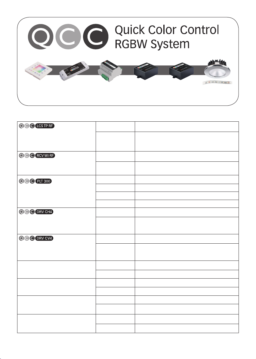
DISPOSITIVI PER LA REALIZZAZIONE DI UN SISTEMA RGBW COMPLETO
• DEVICES FOR GETTING A COMPLETE RGBW SYSTEM • DISPOSITIFS POUR LA RÉALISATION D’UN SYSTÈME RGBW COMPLET
• GERÄTE FÜR DIE REALISIERUNG EINES KOMPLETTEN RGBW SYSTEMS • DISPOSITIVOS PARA LA REALIZACIÓN DE UN SISTEMA RGBW COMPLETO
QCC-LCS TP
QUICK COLOR CONTROL
LIGHT COLOR SELECTOR - TOUCH PANEL
Dispositivo di comando DMX
DMX control device
Alimentazione
Voltage Input
10÷30Vdc
Output
Segnale di comando DMX512
DMX512 command signal
QCC-RCV WI/RF
WI FI/RF RECEIVER TO DMX512 OUTPUT
Ricevitore convertitore Wi Fi/RF-DMX
Wi Fi/RF-DMX converter receiver
Alimentazione
Voltage Input
10÷30Vdc
Output
Segnale di comando in DMX per QCC-PLT 300
Command signal in DMX to QCC-PLT 300
QCC-PLT 300
QUICK COLOR CONTROL - PILOT 300 WATT
Dispositivo di gestione
del sistema RGBW
Quick RGBW system management device
Alimentazione
Voltage Input
10÷30Vdc
Input
DMX512 o pulsanti
DMX512 or push-buttons
Output
Segnale di controllo per QCC-DRV
Control signal to QCC-DRV
Potenza gestibile
Manageable power
Fino a 300W a 24V
Up to 300W at 24V
QCC-DRV CH4
QUICK COLOR CONTROL - DRIVER CHANNELS 4
Driver per faretti RGBW
RGBW downlights driver
Input
Segnale di controllo da QCC-PLT 300
Control signal from QCC-PLT 300
Output
Corrente costante 350mA max per ogni colore,
per pilotare i faretti QCC RGBW
350 mA max constant current for each colour,
to drive the QCC RGBW downlights
QCC-DRV CV4
QUICK COLOR CONTROL - DRIVER CHANNELS 4
Driver per faretti RGBW
RGBW downlights driver
Input
Segnale di controllo da QCC-PLT 300
Control signal from QCC-PLT 300
Output
Tensione costante - Max 2,5A
per pilotare la QCC STRIP LED RGBW
Constant voltage - Max 2,5A
to drive the QCC STRIP LED RGBW
QCC RGBW DOWNLIGHTS
Faretti RGBW (vari modelli)
Downlights RGBW (different models)
Input
Corrente costante 350mA max per ogni colore da QCC-DRV CH4
350 mA max constant current for each colour from QCC-DRV CH4
Power
6W max (tutti i colori accesi al massimo dell’intensità)
6W max (all colours ON at maximum intensity)
QCC RGBW RETRACTABLE BUILT-IN-LAMPS
Lampade ad incasso retrattili RGBW (vari modelli)
RGBW Retractable built-in-lamp (different models)
Input
Segnale di controllo da QCC-PLT 300
Control signal from QCC-PLT 300
Power
8W max (tutti i colori accesi al massimo dell’intensità)
8W max (all colours ON at maximum intensity)
QCC CLG RGBW CHALLENGER SERIES
Luci subacquee RGBW (vari modelli)
Underwater lights (different models)
Input
Segnale di controllo da QCC-PLT 300
Control signal from QCC-PLT 300
Power
da 30W a 60W max (tutti i colori accesi al massimo dell’intensità)
30/60W max (all colours ON at maximum intensity)
QCC RGBW STRIP LED
STRIP LED RGBW
Input
Tensione costante da QCC-DRV CV4
Constant voltage from QCC-DRV CV4
Power
11W/m @ 24V (tutti i colori accesi al massimo dell’intensità)
11W/m @ 24V (all colours ON at maximum intensity)
• Alcuni di questi prodotti sono citati nel presente manuale
• Some of these products are mentioned in this manual • certains de ces produits sont mentionnés dans
ce manuel
• einige der Produkte werden im vorliegenden Handbuch genannt • algunos de estos productos son mencionados en el presente manual.
QCC-PLT 300
QUICK RGBW SYSTEM
MANAGEMENT DEVICE
QCC-RCV WI/RF
WI FI/RF RECEIVER
TO DMX512 OUTPUT
QCC-DRV CH4
DRIVER FOR RGBW
DOWNLIGHTS
QCC-LCS TP RF
RF CONTROL DEVICE
QCC-DRV CV4
DRIVER FOR RGBW
STRIP LED
QCC RGBW
DOWNLIGHTS - STRIP LED
UNDERWATERS
RETRACTABLE BUILT-IN-LAMPS

4
QUICK SPA
QCC CLG30 RGBW - REV001B
La messa in funzione e la manutenzione dell’apparecchiatura deve essere effettuata da personale qualificato.
Rispettare le prescrizioni riportate nel seguente manuale e le norme applicabili alla costruzione elettrica, in modo da garantire
il corretto funzionamento dell’ apparecchiatura e la sicurezza delle persone e dell’ambiente.
Il prodotto modificato o manomesso perde la garanzia del costruttore e la certificazione , e può presentare problemi di
sicurezza per le persone e per l’ambiente.
PRECAUZIONI ED AVVERTENZE
IT
CAUTIONS AND WARNING
EN
PRECAUTIONS ET AVERTISSEMENT
FR
VORSICHTSMASSNAHMEN UND HINWEISE
DE
PRECAUCIONES Y ADVERTENCIAS
ES
La puesta en funcionamiento y el mantenimiento del equipo debe realizarse por personal calificado.
Respete los requisitos indicados en el siguiente manual y las normas aplicables a la fabricación eléctrica para garantizar el
funcionamiento correcto del equipo y la seguridad de las personas y del ambiente.
El producto modificado o alterado pierde la garantía del fabricante y la certificación , y puede presentar problemas de
seguridad para las personas y para el ambiente.
Die Inbetriebnahme und Wartung des Geräts muss von qualifiziertem Fachpersonal ausgeführt werden.
Die im nachfolgend aufgeführten Vorschriften und Normen bezüglich elektrischer Gerätschaften müssen befolgt werden,
Damit eine ordnungsgemäße Funktion des Geräts und die Sicherheit von Personen sowie der Umweltschutz garantiert werden
können. Ein verändertes oder manipuliertes Produkt verliert seinen Anspruch gegenüber der Herstellerfirma und das
-Zertifikat. Außerdem kann ein solches Gerät die Sicherheit von Personen gefährden sowie umweltschädlich werden.
La mise en fonction et l’entretien de l’équipement doit être effectué par une personne qualifiée.
Respecter les prescriptions reportées dans le manuel suivant et les normes applicables à la construction électrique, afin de
garantir le fonctionnement correct de l’équipement et la sécurité de la personne et de l’environnement.
Le produit modifié ou forcé perd la garantie du constructeur et la certification , et peut présenter des problèmes de sécurité
pour les personnes et l’environnement.
Using and servicing the dimmer pack is restricted to qualified personnel.
Follow the instructions in this manual and all the relevant electrical codes. This will ensure the device’s proper operation and
the safety of people and the environment.
Tampering with the device will void the Manufacturer’s Warranty and the Certification, and may lead to safety issues for
people and the environment.

5
QUICK SPA
QCC CLG30 RGBW - REV001B
QCC CLG30 RGBW
CHALLENGER SERIES
Pag. 4 CARATTERISTICHE / INSTALLAZIONE - Attrezzatura e materiali - Istruzioni: pratica del foro in uno scafo metallico,
pratica del foro in uno scafo in vetroresina con intercapedine
Pag. 5 INSTALLAZIONE - Pratica del foro in uno scafo in vetroresina con intercapedine - Installazione senza passascafo
Pag. 6 INSTALLAZIONE - Installazione con passascafo
Pag. 7 INSTALLAZIONE - Sostituzione luce in acqua
Pag. 8 SCHEMA DI COLLEGAMENTO
Pag. 9 SCHEMA DI COLLEGAMENTO / MANUTENZIONE / DATI TECNICI / DIMENSIONI / GARANZIA
Pag. 28 CARATTERISTICHE / INSTALLAZIONE - Equipos y materiales - Instrucciones: Realización del orificio en un casco metálico,
Realización del orificio en un casco de fibra de vidrio con ipinterespacio
Pag. 29 INSTALLAZIONE - Realización del orificio en un casco de fibra de vidrio con ipinterespacio - Instalación sin pasacasco
Pag. 30 INSTALLAZIONE - Instalación con pasacasco
Pag. 31 INSTALLAZIONE - Sustitución de la luz en el agua
Pag. 32 ESQUEMAS DE CONEXIÓN
Pag. 33 ESQUEMAS DE CONEXIÓN / MANTENIMIENTO / ESPECIFICACIONES TÉCNICAS / DIMENSIONES / GARANTÍA
Pag. 22 CARATTERISTICHE / INSTALLATION - Werkzeug und Material - Anleitung: Ein Loch in den Rumpf aus Metall, Bohren vom
Loch in einen Rumpf aus Glasfaser mit Zwischenraum
Pag. 23 INSTALLATION - Bohren vom Loch in einen Rumpf aus Glasfaser mit Zwischenraum - Installation ohne Borddurchführung
Pag. 24 INSTALLATION - Installation mit Borddurchführung
Pag. 25 INSTALLATION - Auswechseln der Leuchte im Wasser
Pag. 26 ANSCHLUSSPLAN
Pag. 27 ANSCHLUSSPLAN / WARTUNG / TECHNISCHE DATEN / ABMESSUNGEN / GARANTIE
Pag. 16 CARACTÉRISTIQUES / INSTALLATION - Équipements et matériaux - Instructions: Perçage de l’orifice dans une coque
métallique, perçage de l’orifice dans une coque en fibre de verre avec interstice
Pag. 17 INSTALLATION - Perçage de l’orifice dans une coque en fibre de verre avec interstice - installation sans passe-coque
Pag. 18 INSTALLATION - Installation avec passe-coque
Pag. 19 INSTALLATION - Remplacement de la lampe dans l’eau
Pag. 20 SCHÉMAS DE BRANCHEMENT
Pag. 21 SCHÉMAS DE BRANCHEMENT / ENTRETIEN / CARACTÉRISTIQUES TECHNIQUES / DIMENSIONS / GARANTIE
INDICE
IT
Pag. 10 CHARACTERISTICS / INSTALLATION - Tools and materials - instructions hole drilling in a metal hull,
hole drilling in a cored fiberglass hull
Pag. 11 INSTALLATION - Hole drilling in a cored fibreglass hull - Installation without a thru-hull fitting
Pag. 12 INSTALLATION - Installation with a thru-hull fitting
Pag. 13 INSTALLATION - How to replace the spotlight underwater
Pag. 14 CONNECTION DIAGRAM
Pag. 15 CONNECTION DIAGRAM / MAINTENANCE / TECHNICAL DATA / DIMENSIONS / WARRANTY
INDEX
EN
SOMMAIRE
FR
INHALTSANGABE
DE
INDICE
ES

6
QCC CLG30 RGBW - REV001B
CARATTERISTICHE / INSTALLAZIONE
IT
QUICK SPA
LEGGERE ATTENTAMENTE PRIMA DI INSTALLARE E COLLEGARE L’APPARECCHIO
Il CHALLENGER è un apparecchio per illuminazione subacquea. Altri usi sono da considerarsi impropri. Quick S.p.A. non potrà
essere perseguita per qualsiasi danno derivato da un uso improprio o diverso da quello previsto nelle presenti istruzioni.
ATTENZIONE
• Non usare mai solventi: pulitori, vernici e altri prodotti che possono contenere solventi. I solventi, come l’acetone, intac-
cano fortemente molte plastiche riducendone la resistenza.
• Non tirare o trasportare il driver con corpo illuminante per i cavi, perché potrebbe danneggiare le connessioni interne e
causare malfunzionamenti al prodotto finale.
Quick S.p.A. non si assume alcuna responsabilità in caso di errato collegamento e/o errato utilizzo di questo
apparecchio.
PRIMA DI UTILIZZARE IL CHALLENGER, LEGGERE ATTENTAMENTE IL PRESENTE MANUALE D'USO.
IN CASO DI DUBBI CONTATTARE IL RIVENDITORE O IL SERVIZIO CLIENTI QUICK®.
ATTREZZATURA E MATERIALI
• Occhiali di protezione • Mascherina contro la polvere
• Trapano elettrico: Punta 3 mm - Tazza 22 mm - Tazza 52 mm (scafo in vetroresina con intercapedine)
- Punta 12 mm (senza passascafo) - Tazza 43 mm (senza passascafo)
• Carta vetrata • Detergente domestico delicato o debole solvente • Sigillante marino.
LA CONFEZIONE CONTIENE:
Challenger QCC CLG30 RGBW + Driver - condizioni di garanzia - manuale d’uso e manuten-
zione - su richiesta manicotto isolante (solo per scafo metallico).
NOTE
- Rispettare le polarità e le istruzioni d’istallazione, utilizzare cavi di spessore adeguato.
- Prima di istallare il CHALLENGER verificare che il banco batterie sia sufficiente al carico totale.
- Non accendere mai il CHALLENGER finché non è immerso in acqua.
ISTRUZIONI
Pratica del foro in uno scafo metallico / vetroresina singolo strato
1. Praticare un foro pilota da 3 mm da dentro lo scafo. Se c’è una sporgenza o qualsiasi altra irregolarità dello scafo vicino
alla zona scelta per il montaggio, forare dall’esterno.
Se il foro pilota è praticato nella zona sbagliata, fare un secondo foro in una posizione migliore. Applicare il nastro
mascherante dall’esterno dello scafo, sopra il foro errato e riempire con resina epossidica.
2. Forare dall’esterno dello scafo utilizzando una tazza da 22 mm (12 mm senza passascafo).
in caso di utilizzo del manicotto nello scafo metallico* utilizzare una tazza da 29 mm (19 mm senza passascafo).
3. Carteggiare e pulire l’area intorno al foro, all’interno ed all’esterno, per assicurare che il sigillante aderisca in modo cor-
retto allo scafo. Se dentro lo scafo c’è qualche residuo oleoso, rimuoverlo con un detergente delicato domestico, o un
debole solvente (alcol) prima di carteggiare.
* In caso di scafo metallico è possibile richiedere il manicotto isolante per evitare corrosioni galvaniche.
Pratica del foro in uno scafo in vetroresina con intercapedine
La zona interna (schiuma) deve essere tagliata e sigillata accuratamente per evitare infiltrazioni d’acqua.
Lo scafo deve essere rinforzato per prevenire eventuali crepe sotto la ghiera di fissaggio che potrebbe allentarsi.
ATTENZIONE: sigillare completamente lo scafo per prevenire infiltrazioni d’acqua nell’intercapedine.
1. Praticare un foro pilota da 3 mm da dentro lo scafo. Se c’è una sporgenza o qualsiasi altra irregolarità dello scafo vicino
alla zona scelta per il montaggio, forare dall’esterno (se il foro pilota è praticato nella zona sbagliata, fare un secondo
foro in una posizione migliore. Applicare il nastro mascherante dall’esterno dello scafo, sopra il foro errato e riempire
con resina epossidica).
2. Utilizzando una tazza da 22 mm forare dall’esterno dello scafo solo la parete esterna lasciando intatta l’intercapedine e
la parete interna.
3. Da dentro lo scafo, usando una tazza da 52 mm, praticare un foro attraverso la parete interna e l’intercapedine senza
toccare la parete esterna. La schiuma nell’intercapedine potrebbe essere molto soffice quindi applicare poca pressione
sulla tazza per evitare di forare anche la parete esterna.
F

7
QCC CLG30 RGBW - REV001B INSTALLAZIONE IT
QUICK SPA
4. Rimuovere il tappo cilindrico di materiale che é stato tagliato. Carteggiare e pulire il bordo interno della parete interna,
la parete di schiuma dell’intercapedine, e il bordo della parete esterna.
5. Inzuppate uno strato di lana di vetro con una resina adatta e disponetelo dentro al foro per sigillare e rinforzare la zona
interna. Aggiungete strati finche il foro è del diametro corretto.
6. Carteggiare e pulire l’area intorno al foro, all’interno ed all’esterno, per assicurare che il sigillante aderisca in modo cor-
retto allo scafo. Se dentro lo scafo c’è qualche residuo oleoso, rimuoverlo con un detergente delicato domestico, o un
debole solvente (alcol) prima di carteggiare.
Esempio foro nello scafo in vetroresina con intercapedine
• Praticare un foro di Ø 12 mm nel punto dove si vuole
applicare il faretto e predisporre lo scafo a seconda del
tipo di materiale costituente (Esempio: rinforzare ed im-
permeabilizzare la zona attorno al foro in caso di scafo in
vetroresina con intercapedine).
• Applicare adeguatamente, attorno al perno, un sigillante
appropriato, senza interruzioni (come indicato nel dise-
gno) ed impermeabilizzare adeguatamente, in funzione
del tipo di scafo, i punti dove vanno applicate le viti di
fissaggio.
• Inserire il cavo poi il perno nel foro dello scafo, ruotare
delicatamente il corpo illuminante in modo da distribuire
uniformemente il sigillante, rimuovere eventuali eccessi
di sigillante.
INSTALLAZIONE SENZA PASSASCAFO
INSTALLAZIONE
MANTENERE
L’ADESIVO DRITTO
Prestare attenzione all’orientamento del prodotto
prendendo come riferimento l’adesivo posto all’in-
terno del corpo luce.
F
• Fissare il prodotto con viti adeguate al tipo di scafo.
• Esaminare attentamente l’installazione in modo da assi-
curarsi che il sigillante offra la completa impermeabilità
del prodotto dove segnalato. In caso di dubbi effettuare
nuovamente l’installazione.
• Ricoprire la cornice metallica esposta all’acqua con ver-
nice antivegetativa idonea.
FORO SCAFO
Ø 12 mm
CAVO
PERNO
CORPO
ILLUMINANTE
Ø 22 mm (7/8”)
Ø 12 mm (7/8”)
Ø 52 mm (2” 3/64)
Ø 43 mm (2” 3/64)
FORO
RESINA EPOSSIDICA
SENZA PASSASCAFO
SENZA PASSASCAFO
INTERCAPEDINE INTERCAPEDINE
RESINA EPOSSIDICA
PARETE INTERNA
PARETE ESTERNA
Completare l’installazione effettuando i collegamenti elettrici. Fare riferimento alla sezione “SCHEMA DI COLLEGAMENTO”
a pag. 10.

8
QCC CLG30 RGBW - REV001B
IT
QUICK SPA
INSTALLAZIONE
INSTALLAZIONE CON PASSASCAFO
ELEMENTI MONTAGGIO ESTERNOELEMENTI MONTAGGIO INTERNO
SPESSORE SCAFO MAX 78 mm
FORO SCAFO
Ø 22 mm
CORPO
ILLUMINANTE
PIASTRA
PASSASCAFO
PASSASCAFO
O-RING
3X45
PASSACAVO
MANTENERE
L’ADESI VO
DRITTO
CAVO
1° RONDELLA
2° RONDELLA
FORO
DI COLLEGAMENTO
PER ANODO
SACRIFICALE
DADO
VITE
DADO DI RITEGNO
Esterno barca fig. 1
• Preparare lo scafo come descritto a pag. 4 e 5.
• Inserire l’o-ring 3x45 nella piastra passascafo facendo at-
tenzione ad inserirlo correttamente nella sede.
• Applicare adeguatamente, attorno alla piastra passasca-
fo, un sigillante appropriato, senza interruzioni (come indi-
cato nel disegno).
• Inserire il cavo e il corpo illuminante nel foro dello scafo,
ruotarlo delicatamente in modo da distribuire uniforme-
mente il sigillante, rimuovere eventuali eccessi di sigillante.
Interno barca fig. 2
• Inserire la 1° rondella nel passascafo.
• Inserire la 2° rondella, le 3 viti, i 3 dadi e il dado di ritegno.
ATTENZIONE
:non tenere le due rondelle troppo vi-
cine. Regolare opportunamente le viti senza stringerle
troppo per evitare fratture nella parete dello scafo.
• Una volta stabilita la giusta distanza tra le due rondelle,
fissare le viti con i dadi facendo attenzione a non farle ruo-
tare ulteriormente.
• Esaminare attentamente l’installazione in modo da assi-
curarsi che il sigillante e l’anello o-ring offrano la completa
impermeabilità del prodotto.
In caso di dubbi rieffettuare l’installazione.
• Ricoprire la cornice metallica esposta all’acqua con ver-
nice antivegetativa idonea.
FIG.1
FIG.2
Prestare attenzione all’orientamento del prodotto
prendendo come riferimento l’adesivo posto all’in-
terno del corpo luce.
F
Completare l’installazione effettuando i collegamenti elettrici. Fare riferimento alla sezione “SCHEMA DI COLLEGAMENTO”
a pag. 10.

9
QCC CLG30 RGBW - REV001B IT
QUICK SPA
SOSTITUZIONE LUCE IN ACQUA (
solo con passascafo)
INSTALLAZIONE
Interno barca
1. Scollegare il corpo illuminate dalla cassetta di derivazio-
ne contenente il driver.
2. Rimuovere la calotta e la guarnizione del passacavo.
3. Montare un tubo di gomma trasparente (Ø interno mini-
no 22 mm), inserendo prima il cavo all’interno, poi fissan-
dolo al perno del passascafo per mezzo di una fascetta
metallica.
4. Fissare l’estremità libera del tubo sopra la linea di gal-
leggiamento.
Esterno barca
5. Dall’esterno del natante rimuovere le tre viti di fissaggio
dal corpo illuminante. Se necessario far leva tra i due ele-
menti Ae Bper scostare il corpo illuminante dallo scafo.
• Sfilare il corpo illuminante con tutto il cavo e riporlo fuori
dall’acqua facendo attenzione a non disperdere le viti di
fissaggio, le grower e l’o-ring.
• Prendere il nuovo corpo illuminante ed inserire preventi-
vamente l’o-ring 3x66 nel cavo.
• Sempre dall’esterno, inserire il cavo nel passascafo e
spingerlo all’interno della gomma ancora installata sul pas-
sascafo.
• Accostare il corpo illuminante alla piastra passascafo
facendo attenzione che l’o-ring entri correttamente nella
sede apposita. Utilizzare le tre viti e le tre rondelle grower
per fissare il tutto allo scafo.
Interno barca
• Rimuovere il tubo in gomma facendo attenzione all’acqua
residua rimasta all’interno dello stesso.
• Re-inserire la guarnizione e la calotta nel cavo, avvitarla al
passacavo per bloccarlo.
CORPO
ILLUMINANTE
PIASTRA
PASSASCAFO
1
2
3
5
4
CASSETTA DI
DERIVAZIONE CON
DRIVER INTERNO
CALOTTAGUARNIZIONE
TUBO DI
GOMMA
O-RING
3X66
A
B
Ripristinare i collegamenti elettrici. Fare riferimento alla sezione “SCHEMA DI COLLEGAMENTO” a pag. 10.

10
QCC CLG30 RGBW - REV001B
IT
QUICK SPA
SCHEMA DI COLLEGAMENTO
DRIVING CABLEPOWER BUS CABLEPOWER BUS CABLEDRIVING CABLEPOWER BUS CABLE
POWER BUS CABLE
20-30VDC
QCC-PLT 300
QCC CLG30
RGBW
QCC CLG30
RGBW
Sistema CLG 30 RGBW - comando da dispositivo DMX
SEGNALE DI
COMANDO DMX
DISPOSITIVO DI
COMANDO DMX512
QCC-PLT 300*
Èun dispositivo elettronico indispensabile per
gestire il CLG RGBW utilizzando un bus a due
cavi per fornire l’alimentazione ed il segnale di
controllo ai driver CLG QCC RGBW.
Non incluso nella confezione.
Fare riferimento al manuale del QCC-PLT300
per un corretto uso del dispositivo.
WIRING DIAGRAM
Power
bus
wiring
Power
bus
wiring
123456789G
Driving
cable
wiring
123456789G
ATTENZIONE: NON COLLEGARE DIRETTAMENTE ALLA TEN-
SIONE ELETTRICA DI RETE (220VAC).
ATTENZIONE: NON COLLEGARE DIRETTAMENTE AL SISTE-
MA ELETTRICO DI BORDO*.
ATTENZIONE
: posizionare la scatola driver in una zona dove non
ci sia presenza di gas o vapori infiammabili.
Svitare le 4 viti del coperchio per accedere al driver e collegare i cavi
come mostra l’adesivo interno, facendoli passare dai passacavi predi-
sposti.
Per la connessione del POWER BUS utilizzare un cavo di dimensione
adeguata al carico. Consigliamo di usare sempre un cavo 2x2,5mm
2
.
La connessione del POWER BUS non ha polarità.
Il cavo non è incluso nella confezione.
Effettuare i collegamenti nella cassetta di derivazione contenente il dri-
ver seguendo le indicazioni dell’adesivo applicato nel coperchio interno
della cassetta.
CASSETTA DI
DERIVAZIONE CON
DRIVER INTERNO
CASSETTA DI
DERIVAZIONE CON
DRIVER INTERNO
PASSACAVO
BUS A DUE CAVI
(POWER BUS)
BUS A DUE CAVI
(POWER BUS)
SCHEMA DI COLLEGAMENTO
INTERNO COPERCHIO CASSETTA DI DERIVAZIONE
CON ADESIVO “SCHEMA DI COLLEGAMENTO”.
VITE
OGNI QCC-PLT 300
PUÒ PILOTARE FINO
A 10 CLG30 RGBW

11
QCC CLG30 RGBW - REV001B IT
QUICK SPA
Quick
®
si riserva il diritto di apportare modifi-
che alle caratteristiche tecniche dell’apparec-
chio e al contenuto di questo manuale senza
alcun preavviso.
In caso di discordanze o eventuali errori tra
il testo tradotto e quello originario in italiano,
fare riferimento al testo italiano o inglese.
SCHEMA DI COLLEGAMENTO / MANUTENZIONE / CARATTERISTICHE TECNICHE
F
F
GARANZIA
Il non rispetto delle prescrizioni del presente documento fanno decadere la garanzia.
MODELLO CLG30 RGBW
Input da segnale di controllo
BUS 2 CAVI
Sorgente luminosa
LED
Potenza consumo
30 W
Consumo Ampère
1,25A @ 24V
Protezione LED
Contro l’inversione di polarità
Picchi di voltaggio ± 500 V
Colore luce
RGBW
Grado di protezione (1) IP68
Certificazioni
Marcatura CE
(1) Scatola di alimentazione IP66.
CARATTERISTICHE TECNICHE
MANUTENZIONE
Evitare il formarsi di incrostazioni, tenere pulita la superficie.
DRIVING CABLEPOWER BUS CABLEPOWER BUS CABLEDRIVING CABLEPOWER BUS CABLEPOWER BUS CABLE
20-30VDC
QCC CLG30
RGBW
QCC CLG30
RGBW
Sistema CLG30 RGBW - comando da pulsanti
QCC-PLT 300
INPUT DA
PULSANTI
CASSETTA DI
DERIVAZIONE CON
DRIVER INTERNO
CASSETTA DI
DERIVAZIONE CON
DRIVER INTERNO
PASSACAVO
VITE
BUS A DUE CAVI
(POWER BUS)
BUS A DUE CAVI
(POWER BUS)
DIMENSIONI
APPARECCHI
pagina 36
OGNI QCC-PLT 300
PUÒ PILOTARE FINO
A 10 CLG30 RGBW

12
CHARACTERISTICS / INSTALLATION
EN
QUICK SPA
QCC CLG30 RGBW - REV001B
READ CAREFULLY BEFORE CONNECTING THE DEVICE
The CHALLENGER
is a underwater lighting device. Any other use is incorrect. Quick S.p.A. cannot be prosecuted for any
damage due to an incorrect installation or an incorrect connection or an incorrect use of the device. The correct installa-
tion, connection and use is described in the present paper.
WARNING
• Never use solvents: cleaners, paint and other products may contain strong solvents, such as acetone, which attack
many plastics greatly reducing their strength.
• Never pull, carry or hold the sensor by the cable, it may sever internal connections.
Quick S.p.A will not be responsible in case of wrong connection and misuse of this device.
READ THESE INSTRUCTIONS CAREFULLY BEFORE USING THE
CHALLENGER
. IN CASE OF DOUBT, CONTACT
YOUR DEALER OR QUICK
®
CUSTOMER SERVICE.
TOOLS AND MATERIALS
• Safety goggles • Dust mask
• Electric drill: drill bin 3 mm (1/8’’) - Hole saw 22 mm (7/8’’) - Hole saw 52 mm (2” 3/64’) (Cored fibreglass hull)
- drill bin 12 mm (15/32’’) (without thru-hull) - Hole saw 43 mm (1” 11/16) (without thru-hull)
• Sandpaper • Mild household detergent or weak solvent • Marine sealant • Anti-fouling paint.
THE PACKAGE CONTAINS: Challenger
QCC CLG30 RGBW
+ Driver - conditions of warranty - the manual of installation and
use
- Insulating sleeve can be provided on request (for metallic hulls only).
NOTES
- Follow polarity and installation instructions, use cables of appropriate section.
- Before installing CHALLENGER verify that your batteries are powerful enough to supply energy to your max load.
- Never light on CHALLENGER since it’s out of water.
INSTRUCTIONS
Hole drilling in a metal hull / Single-layer fibreglass
1. Drill a 3 mm pilot hole from inside the hull. If there is a rib, strut, or other hull irregularity near the selected mounting
location, drill from the outside.
In case the pilot hole is drilled in the wrong area, make a second hole in a better spot. Apply the masking tape on the
outer part of the hull on the mistaken hole and fill with epoxy resin.
2. Using the 22 mm hole saw (12 mm without thru-hull), cut the hole from outside the hull.
A 29 mm hole (19 mm without thru-hull) saw if a sleeve is used in the metal hull*.
3. Sand and clean the area around the hole, inside and outside, to ensure that the sealant will adhere properly to the
hull. If there is any petroleum residue inside the hull, remove it with either mild household detergent or a weak solvent
(alcohol) before sanding.
* For metal hulls you can ask for an insulating sleeve to avoid galvanic corrosion.
Hole drilling in a cored fibreglass hull
The core must be cut and sealed carefully. The core must be protected from water seepage, and the hull must be rein-
forced to prevent it from crushing under the hull nut allowing the housing to become loose.
WARNING
: Completely seal the hull to prevent water seepage into the core.
1. Drill a 3 mm pilot hole from inside the hull. If there is a rib, strut, or other hull irregularity near the selected mounting
location, drill from the outside. (if the pilot hole is drilled in the wrong location, drill a second hole in a better location.
Apply masking tape to the outside of the hull over the incorrect hole and fill it with epoxy).
2. Using a 22mm hole saw, cut the hole from outside the hull through the outer skin only.
3. From inside the hull, use a 52mm hole saw to cut through the inner skin and most of the core. The core material can be
very soft. Apply only light pressure to the hole saw after cutting through the inner skin to avoid accidentally cutting the
outer skin.
4. Remove the plug of core material so the inside of the outer skin and the inner core of the hull are fully exposed. Sand
and clean the inner skin, core, and the outer skin around the hole.
5. If you are skilled in fiberglass, saturate a layer of fiberglass cloth with a suitable resin and lay it inside the hole to seal
F

13
INSTALLATION EN
QUICK SPA
QCC CLG30 RGBW - REV001B
and strengthen the core. Add layers until the hole is the correct diameter.
Alternatively, a hollow or solid cylinder of the correct diameter can be coated with wax and taped in place. Fill the gap
between the cylinder and hull with casting epoxy. After the epoxy has set, remove the cylinder.
6. Sand and clean the area around the hole, inside and outside, to ensure that the sealant will adhere properly to the
hull. If there is any petroleum residue inside the hull, remove it with either mild household detergent or a weak solvent
(alcohol) before sanding.
Example of hole in a fiberglass hull with cofferdam
• Drill a Ø 12 mm hole at the point where you want to fit
the spotlight and prepare the hull according to the type
of material it is made of (for instance, reinforce and seal
the area around the hole if you are dealing with a cored
fibreglass hull).
• Apply a continuous line of a suitable sealant around the
bolt (as shown in the sketch) and seal the points where
the fixing screws are fitted according to the type of hull.
• Pass the cable; then insert the bolt in the hull hole.
Gently turn the light body so as to evenly distribute the
sealant. Remove any excess sealant.
INSTALLATION WITHOUT A THRU-HULL FITTING
INSTALLATION
KEEP THE ADHESIVE
LABEL UPRIGHT
Pay attention to the direction of the product. Take the
adhesive label affixed in the light body as reference.
F
• Fasten the product with screws suitable for the kind of
hull.
• Carefully inspect the installation so as to make sure that
the sealant fully seals the product where needed. If in
doubt, repeat the steps to install the product again.
• Apply a suitable anti-fouling paint coat to the metallic
bezel exposed to water.
HULL HOLE
Ø 12 mm
CABLE
PIN
LIGHT BODY
Ø 22 mm (7/8”)
Ø 12 mm (7/8”)
Ø 52 mm (2” 3/64)
Ø 43 mm (2” 3/64)
HOLE
CASTING EPOXY
WITHOUT THRU-HULL
WITHOUT THRU-HULL
CORE CORE
CASTING EPOXY
INNER SKIN
OUTER SKIN
Finish the installation by carrying out the electrical connections. Refer to the section“
CONNECTION DIAGRAM
”on page 16.

14
EN
QUICK SPA
QCC CLG30 RGBW - REV001B
INSTALLATION
INSTALLATION WITH A THRU-HULL FITTING
ELEMENTS FOR EXTERIOR ASSEMBLYELEMENTS FOR INTERIOR ASSEMBLY
MAX HULL THICKNESS 78 mm
HULL HOLE
Ø 22 mm
LIGHT BODY
THRU-HULL
PLATE
THRU-HULL
FIXING
O-RING
3X45
CABLE
OUTLET
KEEP THE
ADHESIVE LABEL
UPRIGHT
CABLE
1° WASHER
2° WASHER
CONNECTING HOLE
FOR A SACRIFICIAL
ANODE
NUT
SCREW
STOP NUT
Boat exterior fig. 1
• Prepare the hull as described on pages 4 and 5.
• Fit the 3x45 O-ring to the thru-hull plate. Be careful you fit
it correctly in its seat.
• Pass the cable and the light body through the hull hole.
Gently turn the light body so as to evenly distribute the
sealant. Remove any excess sealant.
Boat interior fig. 2
• Fit the 1
st
washer to the thru-hull fixing.
• Fit the 2
nd
washer, the 3 screws, the 3 nuts and the stop
nut.
WARNING
:The two washers should not be very
close one to the other. Duly adjust the screws but do
not tighten them too much or the hull wall may break.
• Once the right distance between the two washers is obtained, fix the screws with the nuts. Be careful not to turn them
still further.
• Carefully inspect the installation so as to make sure that the sealant and the O-ring fully seal the product.
If in doubt, repeat the steps to install the product again.
• Apply a suitable anti-fouling paint coat to the metallic bezel exposed to water.
FIG.1
FIG.2
Pay attention to the direction of the product. Take the
adhesive label affixed in the light body as reference.
• Apply a continuous line of a suitable sealant around the
thru-hull plate (as shown in the sketch).
F
Finish the installation by carrying out the electrical connections. Refer to the section“
CONNECTION DIAGRAM
”on page 16.

15
INSTALLATION EN
QUICK SPA
QCC CLG30 RGBW - REV001B
HOW TO REPLACE THE SPOTLIGHT UNDERWATER
(
Only with thru-hull installation)
Boat interior
1. Disconnect the light body from the junction box con-
taining the driver.
2. Remove the cap and the cable outlet gasket.
3. Fit the transparent rubber tube (minimum inner Ø: 22
mm). First fit the cable in, then, secure it to the thru-hull
bolt by means of a metal clamp.
4. Fix the free end of the tube above the waterline.
Boat exterior
5. From outside the vessel, remove the three screws that
fix the light body. If needed, prise between the two ele-
ments Aand Bto detach the light body from the hull.
• Slide off the light body plus its cable and take it out of the
water. Be careful not to lose the screws, grower washers
and O-ring.
• Take the new light body and fit the 3x66 O-ring in the
cable as a first step.
• Always from outside, fit the cable in the thru-hull fixing
and push it into the rubber tube already fitted to the thru-
hull fixing.
• Draw the light body close to the thru-hull plate; be careful
that the O-ring is correctly fitted in the specific seat. Use
the three screws and the three grower washers to fasten
everything to the hull.
Boat interior
• Remove the rubber tube paying attention to the residual
water that may have remained inside it.
• Refit the gasket and the cap to the cable; screw it to the
cable outlet to lock it.
LIGHT BODY
THRU-HULL
PLATE
1
2
3
5
4
JUNCTION BOX
WITH INTERNAL
DRIVER
COVERGASKET
RUBBER
TUBE
O-RING
3X66
A
Restore the electrical connections. Refer to the section “
CONNECTION DIAGRAM
” on page 16.
B

16
EN
QUICK SPA
QCC CLG30 RGBW - REV001B
CONNECTION DIAGRAM
DRIVING CABLEPOWER BUS CABLEPOWER BUS CABLEDRIVING CABLEPOWER BUS CABLE
POWER BUS CABLE
20-30VDC
QCC-PLT 300
CLG 30 RGBW system - control from DMX control device
DMX COMMAND
SIGNAL
QCC-PLT 300*
This is an essential electronic device to man-
age the CLG RGBW by using a bus with two
wires for supplying power and the control
signal to the CLG QCC RGBW drivers.
Not included in the package.
Consult the QCC-PLT300 manual for
instructions to properly use the device.
WIRING DIAGRAM
Power
bus
wiring
Power
bus
wiring
123456789G
Driving
cable
wiring
123456789G
WARNING: DO NOT CONNECT DIRECTLY TO THE POWER
LINE (220VAC).
WARNING: DO NOT CONNECT DIRECTLY TO THE ON-BOARD
ELECTRICAL SYSTEM*.
WARNING
: position the power supply box in an area clear of flam-
mable gases or vapors.
Undo the 4 screws of the cover to reach the driver. Connect the cables
as shown in the internal adhesive label threading them through the spe-
cific cable outlets.
For the POWER BUS connection use a cable having a size suitable for
charge. We recommend a 2x2.5 mm
2
cable.
The POWER BUS connection has no polarity.
The cable is not included in the package.
Make all the connections to the junction box containing the driver fol-
lowing the instructions shown in the sticker affixed to the internal cover
of the box.
JUNCTION BOX
WITH INTERNAL
DRIVER
JUNCTION BOX
WITH INTERNAL
DRIVER
CABLE OUTLET
TWO CABLES BUS
(POWER BUS)
TWO CABLES BUS
(POWER BUS)
CONNECTION DIAGRAM
INTERNAL SIDE OF JUNCTION BOX COVER WITH
‘WIRING DIAGRAM’ ADHESIVE LABEL.
SCREW
EACH QCC-PLT 300
CAN DRIVE UP TO
10 CLG30 RGBW
QCC CLG30
RGBW
QCC CLG30
RGBW
DMX512
CONTROL DEVICE

17
EN
QUICK SPA
QCC CLG30 RGBW - REV001B CONNECTION DIAGRAM / MAINTENANCE / TECHNICAL DATA
Quick
®
reserves the right to modify the tech-
nical characteristics of the equipment and the
contents of this manual without prior notice.
In case of discordance or errors in translation
between the translated version and the
original text in the Italian language, reference
will be made to the Italian or English text.
F
F
WARRANTY
Failure to comply with the prescriptions listed on this document will void the Warranty.
MODEL CLG30 RGBW
Input from control signal
2 CABLES BUS
Light source
LED
Power consumption
30 W
Ampère consumption
1,25A @ 24V
LED protection Against inversion of polarity
Spike protected ± 500 V
Light color
RGBW
Housing protection (1) IP68
Certifications
CE marking
(1) IP 66 power box.
TECHNICAL DATA
MAINTENANCE
It’s necessary to eliminate deposits, keep the surface clean.
DRIVING CABLEPOWER BUS CABLEPOWER BUS CABLEDRIVING CABLEPOWER BUS CABLEPOWER BUS CABLE
20-30VDC
CLG30 RGBW system - control via push-buttons
QCC-PLT 300
INPUT FROM
PUSH-BUTTONS
TWO CABLES BUS
(POWER BUS)
TWO CABLES BUS
(POWER BUS)
JUNCTION BOX
WITH INTERNAL
DRIVER
JUNCTION BOX
WITH INTERNAL
DRIVER
CABLE OUTLET
SCREW
DEVICES DIMENSIONS
page 36
EACH QCC-PLT 300
CAN DRIVE UP TO
10 CLG30 RGBW
QCC CLG30
RGBW
QCC CLG30
RGBW

18
CARACTÉRISTIQUES / INSTALLATION
FR
QUICK SPA
QCC CLG30 RGBW - REV001B
LISEZ ATTENTIVEMENT AVANT D’INSTALLER ET DE BRANCHER L’APPAREIL
Le CHALLENGER est un appareil d’éclairage sous-marin. Toute autre utilisation doit être considérée comme impropre. La
société Quick S.p.A. ne pourra pas être poursuivie pour tout dommage provoqué par une utilisation impropre ou différente
de celle prévue dans les présentes instructions.
ATTENTION
• N’utilisez jamais de solvants: produits de nettoyage, peintures et tout autre produit susceptible de contenir des solvants.
Les solvants, comme l’acétone, attaquent fortement de nombreuses matières plastiques et provoquent ainsi une réduc-
tion de leur résistance.
• Ne tirez pas et ne transportez pas le pilote avec l’élément d’éclairage en le prenant par les câbles parce que ceci risque-
rait d’endommager les connexions internes et de causer des dysfonctionnements du produit final.
La société Quick S.p.A. décline toute responsabilité en cas de branchement erroné et/ou d’utilisation incorrecte
de cet appareil.
AVANT D’UTILISER LE CHALLENGER, LIRE ATTENTIVEMENT LE MODE D’EMPLOI SUIVANT.
EN CAS DE DOUTE CONTACTER LE REVENDEUR OU LE SERVICE CLIENT QUICK®.
ÉQUIPEMENTS ET MATÉRIAUX
• Lunettes de protection • Masque de protection contre la poussière
•
Perceuse électrique: 3 mm - à gorge 22 mm - à gorge 52 mm (coque en fibre de verre avec interstice)
-
Perceuse
12 mm (sans passe-coque) -
à gorge
43 mm (sans passe-coque)
• Papier de verre • Détergent domestique délicat ou faible solvant • Scellant marin • Peinture anti-encrassement.
L’EMBALLAGE COMPREND:
Challenger QCC CLG30 RGBW + Pilote - conditions de garantie - livret d’instructions
- sur demande manchon isolant (uniquement pour coque métallique)
NOTES
- Respectez les polarités et les instructions d’installation, utilisez des câbles d’une épaisseur adéquate.
- Avant d’installer le CHALLENGER, vérifiez que le banc de batteries est suffisant pour la charge totale.
- N’allumez jamais le CHALLENGER tant qu’il n’est pas plongé dans l’eau..
INSTRUCTIONS
Perçage de l’orifice dans une coque métallique / fibre de verre simple couche
1. Percez un orifice pilote de 3 mm depuis l’intérieur de la coque. En présence d’une saillie ou de toute autre irrégularité
de la coque à proximité de la zone choisie pour le montage, perforez depuis l’extérieur.
Si l’orifice pilote est percé dans une zone erronée, pratiquez un deuxième orifice dans un meilleur emplacement.
Appliquez du ruban de masquage depuis l’extérieur de la coque, au-dessus de l’orifice erroné, et remplissez avec de la
résine époxy.
2. En utilisant un trépan de 22 mm (12 mm sans passe-coque), perforez depuis l’extérieur de la coque.
Trépan de 29 mm (19 mm sans passe-coque), en cas d’utilisation du manchon dans la coque métallique*.
3. Poncez au papier de verre et nettoyez la zone située autour de l’orifice, à l’intérieur et à l’extérieur, pour garantir que le
scellant adhère correctement à la coque. En présence d’un résidu huileux à l’intérieur de la coque, éliminez-le en utili-
sant un détergent domestique délicat, ou un solvant faible (alcool), avant de poncer au papier de verre.
* Dans le cas d’une coque métallique, il est possible de commander le manchon métallique isolant pour éviter les corrosions galvaniques.
Perçage de l’orifice dans une coque en fibre de verre avec interstice
La zone interne (mousse) doit être découpée et soigneusement scellée pour éviter toute infiltration d’eau.
La coque doit être renforcée pour prévenir toute fissure éventuelle sous la douille de fixation qui risquerait de se desserrer.
ATTENTION: scellez complètement la coque pour prévenir toute infiltration d’eau dans la interstice.
1. Percez un orifice pilote de 3 mm depuis l’intérieur de la coque. En présence d’une saillie ou de toute autre irrégularité
de la coque à proximité de la zone choisie pour le montage, perforez depuis l’extérieur (si l’orifice pilote est percé dans
une zone erronée, pratiquez un deuxième orifice dans un meilleur emplacement. Appliquez du ruban de masquage
depuis l’extérieur de la coque, au-dessus de l’orifice erroné, et remplissez avec de la résine époxy.)
2. En utilisant un trépan de 22 mm, perforez depuis l’extérieur de la coque la paroi externe uniquement, en laissant l’in-
terstice et la paroi interne intactes.
F

19
INSTALLATION FR
QUICK SPA
QCC CLG30 RGBW - REV001B
3. De l’intérieur de la coque, en utilisant un trépan de 52 mm, percez un orifice à travers la paroi interne et l’interstice
sans toucher la paroi externe. La mousse de l’interstice pourrait être très légère; par conséquent, appliquez peu de
pression sur le trépan pour éviter de perforer également la paroi externe.
4. Retirez le bouchon cylindrique de matériau qui a été découpé. Poncez au papier de verre et nettoyez le bord intérieur
de la paroi interne, la paroi de mousse de l’interstice et le bord de la paroi externe.
5. Imprégnez une couche de laine de verre avec une résine appropriée et introduisez-la à l’intérieur de l’orifice pour scel-
ler et renforcer la zone interne. Ajoutez des couches jusqu’à ce que l’orifice atteigne le diamètre correct.
6. Poncez au papier de verre et nettoyez la zone située autour de l’orifice, à l’intérieur et à l’extérieur, pour garantir que le
scellant adhère correctement à la coque. En présence d’un résidu huileux à l’intérieur de la coque, éliminez-le en utili-
sant un détergent domestique délicat, ou un solvant faible (alcool), avant de poncer au papier de verre.
Exemple d’orifice dans une coque en fibre de verre avec interstice
• Percez un orifice de Ø 12 mm à l’endroit où vous souhaitez
appliquer le corps d’éclairage et préparez la coque en fonction
de sa composition (exemple: renforcez et imperméabilisez la
zone située autour de l’orifice dans le cas d’une coque en fibre
de verre avec interstice).
• Appliquez correctement, autour de l’axe, un scellant appro-
prié, sans interruptions (comme indiqué sur le schéma) et
imperméabilisez de façon adéquate, en fonction du type de
coque, les points où doivent être appliquées les vis de fixation.
• Introduisez le câble et puis l’axe dans l’orifice de la coque,
faites tourner délicatement le corps d’éclairage de façon à ré-
partir uniformément le scellant et retirez les excès éventuels
de scellant.
INSTALLATION SANS PASSE-COQUE
INSTALLATION
LAISSEZ
L’ADHÉSIF DROIT
Faites attention à l’orientation du produit en prenant
comme référence l’adhésif situé à l’intérieur du corps
d’éclairage.
F
• Fixez le produit avec des vis adaptées au type de coque.
• Examinez attentivement l’installation pour vous assurer que
le scellant garantit l’imperméabilité totale du produit au ni-
veau des points indiqués. En cas de doutes, répétez l’installa-
tion.
• Recouvrez le support métallique exposé à l’eau avec de la
peinture antisalissure appropriée.
ORIFICE COQUE
Ø 12 mm
CÂBLE
PIVOT
CORPS
D’ÉCLAIRAGE
Ø 22 mm (7/8”)
Ø 12 mm (7/8”)
Ø 52 mm (2” 3/64)
Ø 43 mm (2” 3/64)
FORO
RÉSINE ÉPOXY
SANS PASSE-COQUE
SANS PASSE-COQUE
INTERSTICE INTERSTICE
RÉSINE ÉPOXY
PAROI INTERNE
PAROI EXTERNE
Compléter l’installation en effectuant les raccordements électriques.
Se reporter à la section “
SCHÉMA DE BRANCHEMENT
” à la page 22.

20
FR
QUICK SPA
QCC CLG30 RGBW - REV001B
INSTALLATION
INSTALLATION AVEC PASSE-COQUE
ÉLÉMENTS DE MONTAGE EXTERNEÉLÉMENTS DE MONTAGE INTERNE
ÉPAISSEUR DE LA COQUE MAX 78 mm
ORIFICE COQUE
Ø 22 mm
CORPS D’ÉCLAI-
RAGE
PLAQUE
PASSE-COQUE
PASSE-COQUE
JOINT TORIQUE
3X45
PASSE-CÂBLE
LAISSEZ
L’ADHÉSIF
DROIT
CÂBLE
1eRONDELLE
2eRONDELLE
ORIFICE DE
RACCORDEMENT
DE L’ANODE ACTIVE
ECROU
VIS
ÉCROU DE RETENUE
Extérieur du bateau fig. 1
• Préparez la coque de la façon décrite aux pages 4 et 5.
• Introduisez le joint torique 3x45 dans la plaque passe-
coque en veillant à bien l’insérer dans son logement.
• Appliquez adéquatement, autour de la plaque passe-
coque, un scellant approprié, sans interruptions (comme
indiqué sur le schéma).
• Introduisez le câble et le corps d’éclairage dans l’orifice
de la coque, faites-le tourner délicatement de façon à ré-
partir uniformément le scellant et retirez les excès éven-
tuels de scellant.
Intérieur du bateau fig. 2
• Introduisez la 1
e
rondelle dans le passe-coque.
• Introduisez la 2
e
rondelle, les 3 vis, les 3 écrous et l’écrou
de retenue.
ATTENTION
:ne laissez pas les deux rondelles trop
proches. Réglez adéquatement les vis sans les serrer
excessivement pour ne pas provoquer de fissures
dans la paroi de la coque.
• Après avoir défini la bonne distance entre les deux rondelles, fixez les vis avec les écrous en veillant à ne pas les faire
tourner davantage.
• Examinez attentivement l’installation pour vous assurer que le scellant et le joint torique garantissent l’imperméabilité
totale du produit.
En cas de doutes, répétez l’installation.
• Recouvrez le support métallique exposé à l’eau avec de la peinture antisalissure appropriée.
FIG.1
FIG.2
Faites attention à l’orientation du produit en pre-
nant comme référence l’adhésif situé à l’intérieur du
corps d’éclairage.
F
Compléter l’installation en effectuant les raccordements électriques.
Se reporter à la section “
SCHÉMA DE BRANCHEMENT
” à la page 22.
Table of contents
Languages:
Popular Lighting Equipment manuals by other brands

Lightolier
Lightolier Calculite 7794QD specification

Clas Ohlson
Clas Ohlson WX-LED44-260WW-10-2 quick start guide

Aqua Creek Products
Aqua Creek Products F-004AB instructions

EuroLite
EuroLite LED BAR-6 user manual

Solight
Solight WM58 quick start guide

Lightolier
Lightolier Lightolier E1 Series Specifications