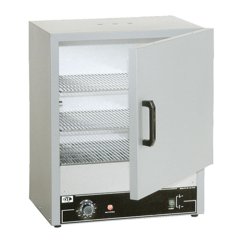
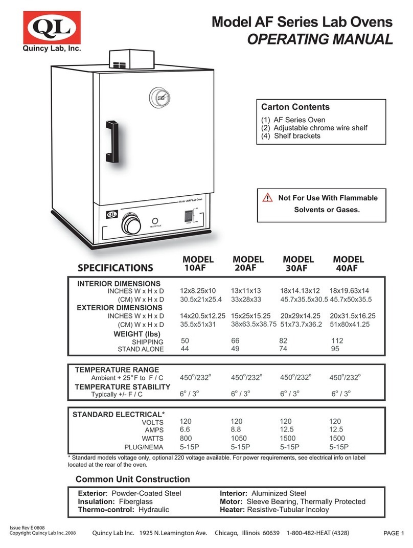
Quincy lab 140-1 Series User manual

PAGE 1
Issue Rev A 0309 Quincy Lab Inc. 1925 N. Leamington Ave. Chicago, Illinois 60639 1-800-482-HEAT (4328)
Copyright Quincy Lab Inc. 2009
Model Series 140-1 & 180-1 (230 V )
General Purpose Incubators
OPERATING MANUAL
Quincy Lab, Inc.
HEAT/CYCLE
POWER
Model 12-140 Incubator
Interior Dimensions
INCHES W x H x D
(CM) W x H x D
Exterior Dimensions
INCHES W x H x D
(CM) W x H x D
12x10x10 18x16x12 18x16x1212x10x10
13x15x11 19x21x13 13x15x11 19x21x11
Weight (lbs) 19 lbs 33 lbs 19 lbs 33 lbs
Standard Electrical: 230 volts, 50/60 Hz
31x25x25 46x41x30 46x41x3031x25x25
33x38x28 48x53x33 33x38x28 48x53x33
SPECIFICATIONS MODEL
10-140-1 MODEL
12-140-1 MODEL
10-180-1 MODEL
12-180-1
Temperature Range
Ambient + 2
o
C to 62
o
C
Common Unit Construction
Exterior: Powder-Coated Steel Interior: Aluminum
Insulation: Fiberglass Door: 140-1: Acrylic, 180-1: Steel Insulated
Thermo-control: Bi-Metal Heater: Resistive-Tubular Incoloy
WATTS 120 235 270 385
HEAT/CYCLE
POWER
Model 10-180Incubator
Ambient + 3
o
C to 94
o
C
Cubic Foot Capacity
.7 ft32.0 ft3.7 ft32.0 ft3
Model 10-180-1
Model 12-140-1
Common Unit Specifications
Operating Environment: Indoor use, altitude to 6,500 ft. (2,000m) Installation Category II,
Pollution Degree 2, ambient temperature 10oC/50oF to 35oC/95oF,
80% RH maximum.
Storage Temperature: -10oC/14oF to 70oC/158oF, 70% RH maximum.
Approvals: Underwriter's Laboratory Listed, Laboratory Equipment, C/UL
United States/Canadian. E212550 (115VAC models only)
Compliance: UL Standard 61010-1, IEC 61010-1, 2nd Edition.

Receiving
After unpacking, verify receipt of correct quantities of each component and that each component has
not suffered any shipping damage. If there are any problems, please refer to the enclosed
Damaged/Missing Item Report.
FIG. 4
Set-up & Installation
Place the unit on its back with the bottom surface facing you.
Install the (4) rubber feet into the (4) mounting holes by
pressing in and turning. (FIG 1) Do not operate unit without
the feet installed.
Place the unit upright. Position unit in its ultimate operating
location. Keep a minimum of 2" of airspace around the unit
and a minimum of 16" above the unit to allow for
thermometer.
FIG. 1
A
B
C
D
FIG. 2
FIG. 3
PAGE 2
Remove the glass thermometer from its container and insert
into the rubber grommet. (FIG 2)
Insert the rubber grommet/thermometer assembly into the
port through the top of the incubator. The thermometer
should extend into the incubator at least 1-1/2". (FIG 3)
Install adjustable shelf by placing the ends of the wire shelf
bracket into the corresponding holes located on the inner
sides of the oven at the desired height. Push the ends of the
bracket into the holes until the first bends in the bracket are
against the wall, then rotate the bracket down. Place the shelf
on the brackets. (FIG 4)
Plug the unit into a grounded outlet for your unit's rated
voltage. See units electrical label located on rear panel.
Read Operating Instructions thoroughly prior to operation. Use only a grounded outlet that is rated for
your models' electrical requirement. Do not modify the oven or factory control settings to operate the
oven above the stated maximum operating temperature. Exterior surfaces on the 180-1 models may
become hot to the touch when operating at higher set temperatures. Conduct periodic maintenance
as required.
Read Operating Instructions Thoroughly Prior to Operation
Safety Precautions

PAGE 3
Push the illuminated power button. Rotate the thermostat knob clockwise to approximately the number
6 on the dial. The heat cycle light will illuminate to indicate that the heating element is energized.
Observe the thermometer. When the desired temperature is reached, slowly turn the thermostat knob
counter clockwise until the heat cycle indicator turns off. The temperature will continue to rise slightly
due to latent heat from the heating element.
Allow unit to cycle empty for a minimum of 20 minutes to allow the interior chamber to reach a thermal
equilibrium. Check the thermometer to see if any minor adjustments to the thermostat should be made.
With any subsequent adjustment allow time for chamber to achieve a steady state before determining if
the desired set temperature has been reached. To keep from resetting a frequently used set
temperature with each use, leave the thermostat knob at its set point and use the power button to turn
the unit on or off.
Setting the unit's temperature with an empty chamber helps to establish a useful correlation between
the unit's performance (heating capacity) and proper processing of various chamber loads and
densities (load-effect). See Performance and Chamber Loading & Important Operational Notes.
FIG. 7FIG. 5 FIG. 6
(cont.)
Understanding the unit's light pressure thermal convection and "load-effect" are necessary to
optimizing unit performance. Article or media processing times and/or uniformity are largely dependent
on load density and positioning. When processing various loads it's important to remember that the
thermostat senses the temperature at the lower part of the chamber where the heat is generated and
the corresponding reading of a temperature setting is taken from the top of the chamber with the
installed thermometer. Since loads sit between these two points, load variations such as quantity,
arrangement, density and their relative thermal properties can temporarily or permanently affect
temperature readings. Here are important guidelines to chamber loading and processing:
Load the incubator so that air circulation within the chamber is not impaired. Leave a space between
articles on a shelf. Stagger articles from those on lower shelves in a "V" formation. (FIG 5).
Use of large solid trays or foil on lower shelves severely limits heat to shelves and articles placed
above. (FIG 6) Since not enough heat rises within the chamber, thermometer readings give false
indication that the temperature setting is too low. Higher temperature adjustments made as a result
of these readings could overheat lower placed articles or media.
General Operation
Performance and Chamber Loading

PAGE 4
Maintenance
To clean interior and exterior surfaces, use a damp cloth with or without an all-purpose cleaner. The
acrylic door, (on 140 Models), should only be cleaned using a lint-free cloth. Paper towels can mar the
surface of the acrylic door. Use of any commercial cleansers on the acrylic door will cause crazing and
cracking of the surface of the acrylic door over time. Periodically check the temperature stability (with the unit
empty of contents), by observing the temperature through several cycles of the thermostat. (See also
Important Operational Notes above).
If you have any questions or need technical assistance, please contact Quincy Lab customer support at
Voice: 800-482-HEAT Quincy Lab, Inc.
Fax: 773-622-2282 1925 North Leamington Avenue
Important Operational Notes:
The set point of the thermostat or chamber temperature stability can be affected by changes in ambient
(room) temperature and/or equipment running in close proximity (creating micro climates) or cycling on
the same electrical circuit. Take time to see how unit location or changes in room temperature from
seasonal heating or air conditioning may influence the incubator's set temperature. For best chamber
temperature stability, keep the ambient temperature stable.
The unit's minimum operating temperature is largely determined by ambient temperature. The unit can
operate 2 degrees above room temperature but temperature stability will be degraded. Stability
improves appreciably for settings that exceed ambient by 4 degrees C or better. Also, the lower the
ambient temperature the lower the maximum adjustable operating temperature. Adjusting the
operational temperature range of the unit for non-typical ambient conditions can be done by adjusting
the calibration trim screw located recessed in the shaft, behind the knob dial. If a temperature range shift
is necessary, contact factory for instructions.
Avoid extremely large (in quantity or size), or high-density loads. (FIG 7) This will show by non-uniform
processing and long or impossible "heat-through" times. To help determine a large load's suitability,
use the set-point recovery time (the time it takes for the temperature to recover to the original set
temperature once load is placed), as a guide. To reduce recovery time, reduce load proportionally.
Also, large loads such as a beaker containing 2 liters of solution may require an elevated set
temperature for the solution to reach and maintain a lower target temperature. When possible,
measure large loads or solution temperatures directly with an ancillary thermometer or probe. Probes
can be inserted at top port.
Quincy Lab, Inc. warrants to the original purchaser that this product will be free from defects in material
and workmanship under normal use throughout the warranty period. The standard warranty period for
this instrument is 18 months, (3-year coverage on the heater element), from date of
shipment. Please refer to your invoice or shipping documents to determine the
effective warranty period. This warranty covers parts and labor (labor at factory
only), and shipping cost for replacement parts.
Performance and Chamber Loading (cont.)
Process the smallest possible load the application or workload will permit. For best processing of small
multiples or a single item, adjust one shelf so that the article(s) is centered in the incubator. Avoid
placing articles or media against or within an inch of the walls especially on the lower shelf. Heated air
from the lower plenum openings, designed to travel up the side walls, can have a slightly elevated
temperature from set point and the rest of the chamber.
Tech Support
Limited Warranty
This manual suits for next models
5
Table of contents
Other Quincy lab Laboratory Equipment manuals
Popular Laboratory Equipment manuals by other brands

Ocean Insight
Ocean Insight OCEANHDX RAMAN quick start guide

BANDELIN
BANDELIN DT 31 H operating manual

Mecmesin
Mecmesin Vortex operating instructions

NuAire
NuAire LabGard NU-545-300E Operation and maintenance manual

IKA
IKA RV 10.1 Mounting instruction

Sartorius
Sartorius WZA225-CW installation instructions