Press and hold until you see T.STR
Basic Count Down Timer Function (Menu 3)
Control Calibration to Match Independent Device
IMPORTANT
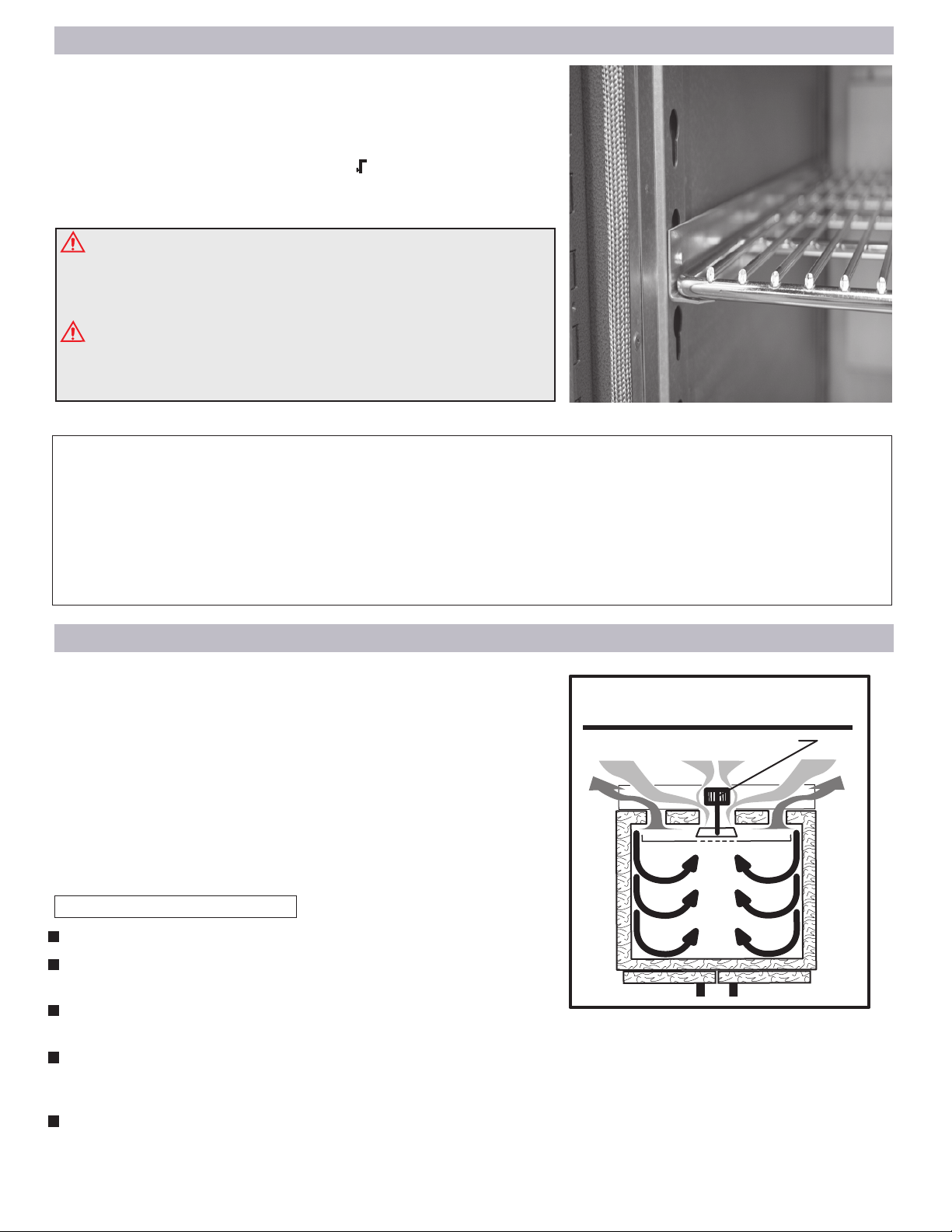
The most accurate calibra�on possible for any digital unit is at
the center of the chamber (with the chamber empty). Therefore,
calibrate the control to the center of the chamber using an accu-
rate temperature measuring device.
Calibra�ng the actual chamber temperature to the temperature
displayed on the controller should only be done if the chamber’s
temperature, as measured by a known accurate device, is off by
more than the stated tolerance of your Bench Oven.
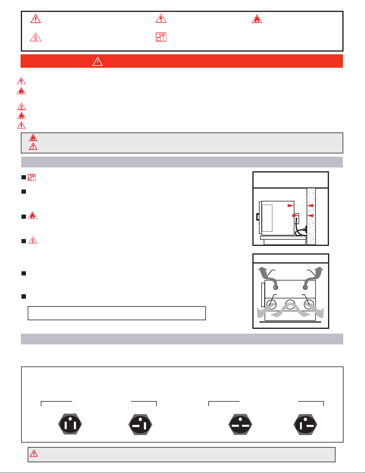
Your oven’s controller offset value has been input at the factory to match
your oven’s true chamber temperature when measured at the center of
the oven using an NIST (National Institute of Standard and Technology)
traceable temperature box (FIG.11). Over time this offset value may need
to be adjusted. If an offset needs to be performed in the field, place a
temperature probe at the center of the oven and adjust as needed.
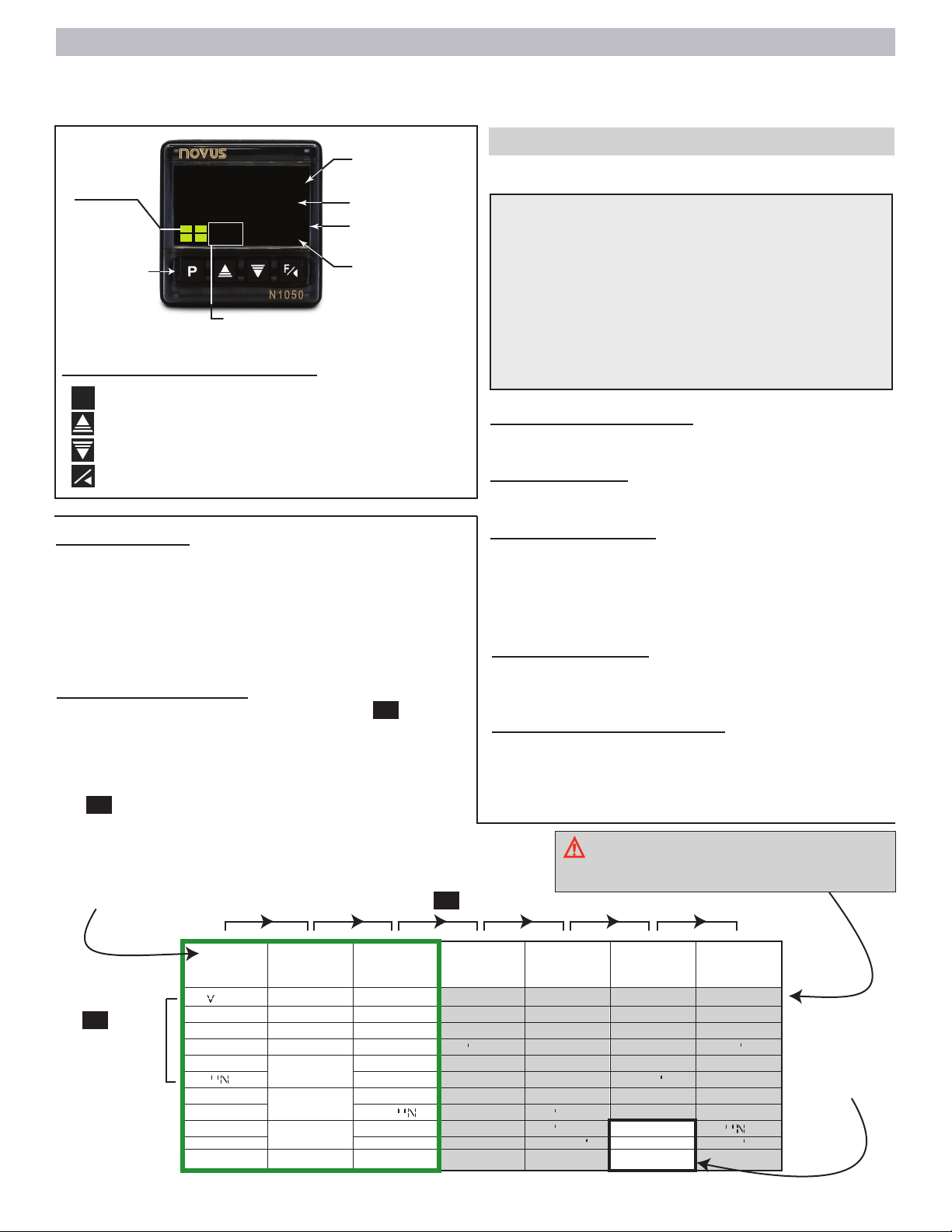
CALIBRATION EXAMPLE:
In the example shown in (FIG.12), the digital controller process value
reads 150°F (white LEDs) and the independent temperature probe
placed at the center of the oven shows a reading of 155°F. Note the
difference of 5 degrees F between the temperatures. On the controller’s
OFFS parameter, for this example, we add the 5°F difference to the
offset value already present. This value change will adjust the process
value on the controller to match the chamber temperature of 155°F.
OFFS
0
PF
PF
Press 3 times to
see OFFS
Press up or down
to input difference
PFPress 3 times to
return.
Once a temperature adjustment has been made, allow the oven some
time to stabilize before making any subsequent adjustments.
The temperature difference between the controller and your independent
probe can be a positive or negative number.
OFFSET VALUE
150°F
155°F
Independent temperature
measuring device.
Independent temperature probe
ACCESS THE OFFSET PARAMETER BY:
Your oven’s controller is equipped
with a timer feature that allows
you to use a count down timer by
manual activation.
For additional timer options see
Timer on pg2 of the QR-code pdf.
T.STR
F
T.DIR
DN
T.TB
: SS
Time Start Mode (T.STR)
The (F) value allows the timer to be
manually activated by pressing once
steps are completed.
Time Count Direction (T.DIR)
F
MM
Time Base Setting ( T.TB)
Access this parameter and choose the
desired timer base setting.
T1
T.PU
ON
Time Interval Adjustment (T1)
Acess this parameter and input the
desired timer value using the UP or
DOWN arrow keys .
T.PU Behavior at end of timer
This parameter allows the unit to continue
or stop with the heating operation after the
timer option is finished. Choose one of the
following:
00:00
HH:MM - Time intervals are diplayed in
hours and minutes.
MM:SS - Time intervals are diplayed in
minutes and seconds.
T1.E
Set this parameter to NO. Continue to next timer parameter.
T. END
Set this parameter to OFF. Continue with the next timer parameter.
T2
Set this parameter to 0000. Continue with the next timer parameter.
N
N
ON - Temperature controller continues
to operate.
OFF - End controller heating operation
at the end of the timer.
If the OFF option is selected, at the end of the timer
the RUN function will need to be enable to YES for
oven to heat again. See RUN FUNCTION on page 6.
Step 1
Step 2
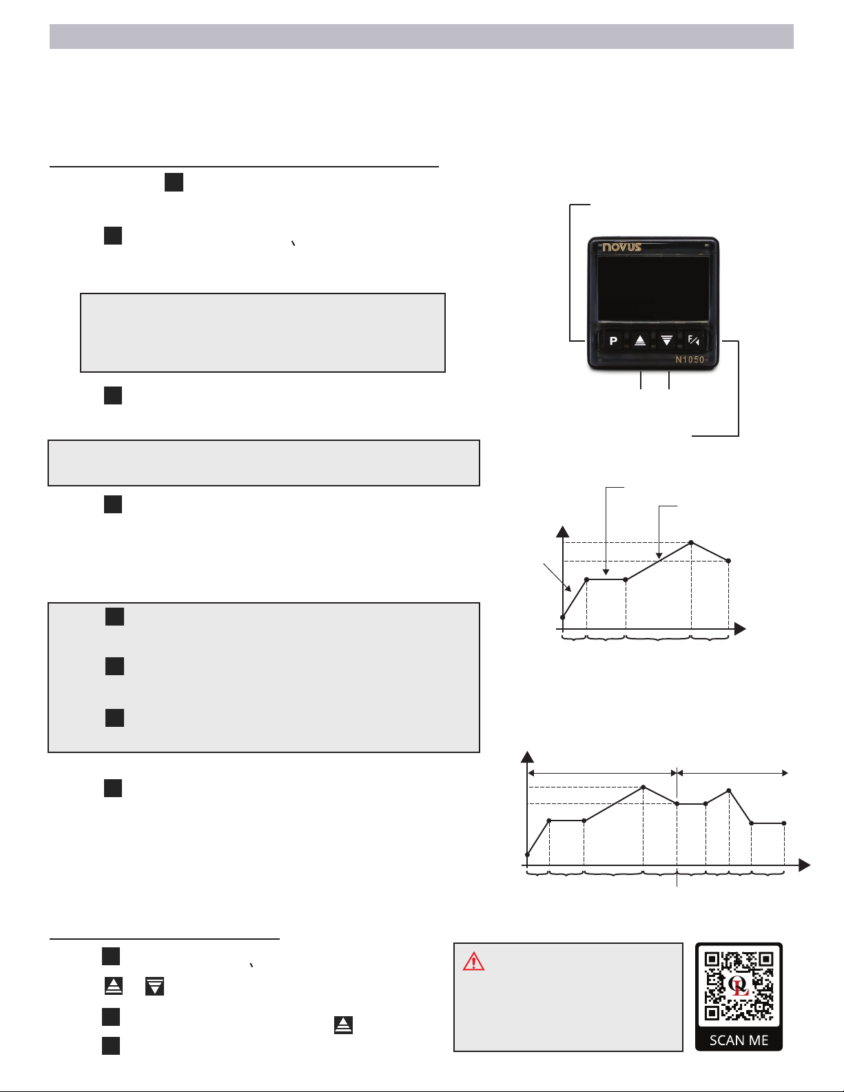
Starting the timer
Once timer is set, you can start, pause,
and stop/cancel the timer count by doing
the following:
F
Step 6
Setting the count down timer
Start - Press once.
Pause - Press once.
F
Stop / Cancel - Press for 3 seconds.
F
When the timer has activated, the indica-
tor (A3) will flash continuously.
When the timer is interrupted the indica-
tor (A3 or A4) will flash quickly.
P
(Press to advance to Step 2)
P
This tells the controller to count in a down
direction.
Step 3
and press to select F
T1.E
As you are pressing and holding you may go pass
T.STR , if this happens, simply continue to press
and hold until parameter T.STR is reached.
P
P(Press once more to complete set-up and return to
temperature display)
P
Press to select DN
Press to advance to Step 3 or to return to previous
PF
Using the or keys and select a desired
time base to apply to the timer.
Press to advance to Step 4 or to return to previous
PF
Step 4
Press to advance to Step 5 or to return to previous
PF
Using the or keys and select a desired
time.
Step 5
Set the following (3) parameters as follows and
press to advance :
Press to advance to Step 6 or to return to previous
PF
P
Using the or key select what happens
at the end of the timer.
There are other timer options available,
but only Fwill work as a count down timer.
Digital
controller
process
value
PAGE 7
FIG. 11
FIG. 12