QWICK KURB MEGA MARKER L104 User manual

QWICK KURB, INC.
Long Term Installation Manual
©
1916 US 41 South, Ruskin, FL 33570
Phone: 800-324-8734 Fax: 813-645-4856 www.qwickkurb.com
Revision:
3.3
March 2014
June 2015
January 2016
© 2014 QWICK KURB®, INC.
®

QWICK KURB®, INC. Long Term Installation Manual
Interstate Application
Median Application
Edge Line Applications
Private/Proprietary: Not for use or disclosure outside of QWICK KURB®, INC. except by written agreement.
Phone: 800-324-8734 Fax: 813-645-4856 www.qwickkurb.com
1/21/2016
2

QWICK KURB®, INC. Long Term Installation Manual
Table of C
o
ntent
s
INSTRUCTIONS FOR LONG TERM INSTALLATION - 2016 ...............................................6
INTRODUCTION..........................................................................................................................................6
INSTALLATION CONDITION
S
...................................................................................................7
TRAFFIC CONSIDERATIONS....................................................................................................................7
SKID RESISTANT GRIPS.............................................................................................................................................................7
WEATHER CONDITIONS ..........................................................................................................................7
TOOLS AND EQUIPMENT CHECKLIST ...................................................................................8
PARTS
CHECKLIST
.........................................................................................................................9
ILLUSTRATED
PARTS
..................................................................................................................10
PREPARING THE ROADWAY FOR IN
STALLAT
ION..........................................................12
CLEANING THE ROADWAY SURFACE...............................................................................................12
LINING THE INTENDED PATHWAY ...................................................................................................12
WATER CHANNELS AND SPACING MARKERS/BOLLARDS .........................................13
USING WATER CHANNELS ...................................................................................................................13
SPACING THE REBOUNDABLE MARKERS/BOLLARDS ................................................................13
SETTING THE L60 SEPARATOR UNITS INTO POSITION ................................................14
SETTING THE L60 SEPARATOR UNITS................................................................................................14
DO NOT DRAG THE L60 SEPARATOR UNITS..................................................................................14
CONNECTING THE L60 SEPARATOR UNITS ...................................................................................17
INSTALLING THE L65 REFLECTIVE ARCS..........................................................................................18
INSTALLING TO THE ROADWAY ...........................................................................................19
FINE TUNING.............................................................................................................................................19
BOLTING TO THE ROADWAY – ASPHALT AND CONCRETE ………….....................................19
INSTALLING THE MARKERS/BOLLARDS .........................................................................................21
ALTERNATE PROCESS: THE Q640 PANEL PULLER TOOL .......................................................... 23
SECURING THE MARKER/BOLLARD WITH THE S65 BLACK SECURING ARCS.......................23
Phone: 800-324-8734 Fax: 813-645-4856 www.qwickkurb.com
1/21/2016
3

QWICK KURB®, INC. Long Term Installation Manual
REMOVAL
........................................................................................................................................25
TRAFFIC CONSIDERATIONS..................................................................................................................25
REMOVING THE MARKERS/BOLLARDS............................................................................................25
REMOVING THE L65 REFLECTIVE ARCS............................................................................................25
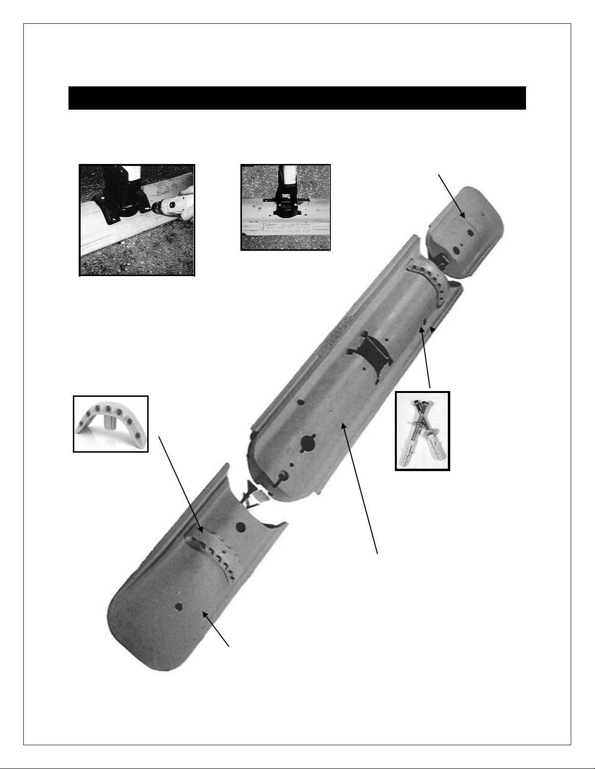
DISASSEMBLING THE L60 SEPARATOR UNITS ................................................................................25
UNBOLTING FROM THE ROADWAY - ASPHALT ............................................................................26
PICKING UP THE L60 SEPARATOR ......................................................................................................26
DO NOT DRAG THE L60 SEPARATOR UNITS..................................................................................26
MAINTENANCE .............................................................................................................................27
STORAGE .........................................................................................................................................28
TRANSPORT....................................................................................................................................29
CUSTOMER
SER
VIC
E
...................................................................................................................30
REPLACEMENT PARTS............................................................................................................................30
MEASUREMENTS ......................................................................................................................................30
APPENDIX A - Q640 PANEL
PULLER
........................................................................................31
QWICK INSTALLATION ..........................................................................................................................31
APPENDIX B - INSTALLING NEW MARKERS/BOLLARDS TO THE
REBOUNDABLE FLEX
B
OO
T
......................................................................................................34
TRAFFIC CONSIDERATIONS..................................................................................................................34
REMOVING THE OLD MARKER/BOLLARD FROM THE REBOUNDABLE FLEX BOOT..........34
PREPARING THE NEW MARKER/BOLLARD FOR INSTALLATION ON THE
REBOUNDABLE FLEX BOOT ..................................................................................................................34
APPENDIX C – PARTS
SPEC
IFICATION
S
...............................................................................36
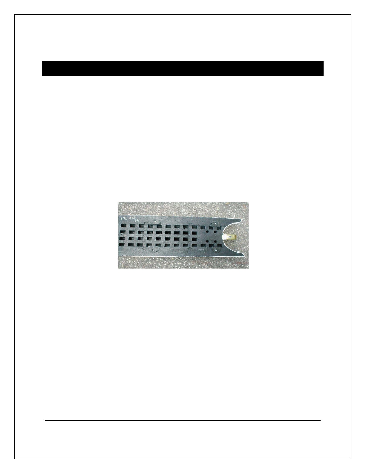
L60 SEPARATOR UNIT .............................................................................................................................36
L61 MALE END UNIT................................................................................................................................37
L62 FEMALE END UNIT...........................................................................................................................38
L65 REFLECTIVE MARKER......................................................................................................................39
S65 SECURING ARC ..................................................................................................................................40
L84 FLAT MARKER/BOLLARD..............................................................................................................41
L104 MEGA MARKER®/BOLLARD.......................................................................................................42
Phone: 800-324-8734 Fax: 813-645-4856 www.qwickkurb.com
1/21/2016
4

QWICK KURB®, INC. Long Term Installation Manual
L125 MARKER/BOLLARD .......................................................................................................................43
L125SH MARKER/BOLLARD..................................................................................................................44
FS50 PAVEMENT ANCHOR …………..................................................................................................45
Phone: 800-324-8734 Fax: 813-645-4856 www.qwickkurb.com
1/21/2016
5

QWICK KURB®, INC. Long Term Installation Manual
INSTRUCTIONS FOR LONG TERM INSTALLATION - 2016
INTRODUCTION
QWICK KURB® is a longitudinal channelizer system of interlocking raised L60 SEPARATOR
units, L65 Reflecting Arcs depicting the raised profile of the L60 SEPARATOR, and vertical
markers and/or bollards. The system is used instead of asphalt or concrete separators of
similar dimensions. It outlasts asphalt, is deployed faster than asphalt and concrete, and it
requires less maintenance. It provides superior guidance for the motorist day and night. It
is ideal as a traffic separator, and as an edge line guide to channel traffic away from
attenuators, to discourage motorists from driving into restricted areas, and to channel in
other desirable ways. Installation is quickly mastered by following the techniques in this
instruction manual. Dimensions mentioned in the instructions are approximate. Refer to
Appendix C – Parts Specifications on page 36 when more precise measurements are
needed.
To install on DRAW BRIDGES, contact QWICK KURB®, INC. to obtain additional instructions.
To install in locations where ROAD DEPTH is restricted, contact QWICK KURB®, INC. to
obtain alternate anchoring instructions.
CAUTION: The L60 SEPARATOR is not intended for use as a substitute where barrier wall
or barrier curb is required. As with temporary asphalt and concrete separator, emergency
and other vehicles are able to traverse the L60 SEPARATOR.
The L60 SEPARATOR is designed to help guide the motorist visually, earn driver respect
for the visual channelization, assist encroaching drivers to promptly recognize that their
vehicles are straying into improper locations, and to minimally deflect the vehicles. The
L60 SEPARATOR is not designed to stop vehicles, or to alter their course in a significant
manner.
When configuring a vee shape to channelize motorists away from attenuators, place the
point of the vee no closer than thirty (30) feet from the attenuator. QWICK KURB® testing has
not included closer positioning.
To minimize maintenance of the markers/bollards, designers should take into consideration
lane width, along with wide load and truck turning radius requirements.
Phone: 800-324-8734 Fax: 813-645-4856 www.qwickkurb.com
1/21/2016
6

QWICK KURB®, INC. Long Term Installation Manual
INSTALLATION CONDITIONS
TRAFFIC CONSIDERATIONS
Whenever possible close both lanes to traffic when installing the System between lanes. If
one lane must be kept open during installation, take care to assure that all equipment and
personnel are kept clear of the open travel lane. Observe all traffic control regulations. Use
flaggers, law enforcement officers, flashing arrow boards, attenuators, and other safety
devices as necessary for the conditions present.
RAISED FEET
On the bottom of each L60 SEPARATOR, each L61 Male and L62 Female End unit, are eight
raised feet, either molded to the L60 SEPARATOR or added for extra height.
The feet raise the L60 SEPARATOR slightly above the pavement surface so that water can
run underneath, though water channels may be necessary if excessive water is likely. Refer
to the Using Water Channels section on page
13 for more information.
WEATHER CONDITIONS
The L60 SEPARATOR can be installed permanently under most weather conditions. Heat
and cold do not present obstacles. However, before working with electrical equipment in
wet conditions, be certain to follow the manufacturer’s instructions to prevent electrical
shock or other damage. Refer to the Installing to the Roadway section on page 19 for more
information.
Phone: 800-324-8734 Fax: 813-645-4856 www.qwickkurb.com
1/21/2016
7

QWICK KURB
®
, INC.
Long Term Installation Manual
TOOLS AND EQUIPMENT CHECKLIST
For a typical installation, we recommend the items listed below.
NOTE: Always follow manufacturers’ instructions when using any power, impact or other tools and
equipment.
Item Description
5 Horsepower Generator 5,000 watts.
Variable Speed Rotary Hammer 300-700 no load rpm and 1,650-3900 rpm; 1” bit capacity, e.g., Bosch Terminator
Model 11222EVSG or Milwaukee Hawk Model 5362-1. Drills holes into asphalt or
concrete for anchors.
Carbide Tipped Bits for Rotary
Hammer
ANSI diameter 3/4”; minimum usable length 10”. The quantity needed depends on the
length and number of installations and the density of the underlying material.
Electric Impact Wrench 1/2”; maximum torque 330 ft. lbs., e.g., Ingersoll-Rand Model IR8053 or DeWalt Model
DW290 – (connects the L60 SEPARATOR with connecting bolt & nut).
15/16” Shallow Socket Use with electric impact wrench to tighten FS50 anchor sets
17mm Shallow Socket Use with electric impact wrench (for L60 SEPARATOR connecting bolt & nut).
Electric Drill 1/2”; 0 to 550 rpm, variable speed e.g., Makita Model 6402 and a 7/16” Six Point
Socket - installs hex screws for S65 black Securing Arcs (use the low setting torque
to avoid striping hex heads.)
Extension Cord 50 foot heavy duty grade 12 gauge.
Rubber Hammer Assists in tapping the markers/bollards and L65 Reflective Arcs into place.
Hammer Taps anchors into the drilled holes.
Soapy Water Assists in sliding the markers/bollards into place.
Stiff Broom Clears debris from the intended placement location for the L60 SEPARATOR.
For lengthy installations in excess of 1,000 feet, you may wish to rent our optional
Conveyor.
To install a large number of markers/bollards you may wish to purchase our Q640 Panel
Puller. Refer to Appendix A on page 31 for more information.
Phone: 800-324-8734 Fax: 813-645-4856 www.qwickkurb.com
1/21/2016
8

QWICK KURB®, INC. Long Term Installation Manual
PARTS CHECKLIST
Refer to the Illustrated Parts section on page 10 and 11 for a close up view of the parts listed
below.
Part Number Description Quantity
L60 QWICK KURB® One-Meter SEPARATOR
Units
The number purchased for the distance of each
adjacent line.
L61 Male End Unit At Least one and any additional L61 Male End
units purchased to include the number of required
water channels contemplated.
L62 Female End Unit
At Least one and any additional L62 Female End
units purchased to include the number of required
water channels contemplated.
L65 Reflective Arc The number ordered.
S65 Black Securing Arc (2) per marker/bollard - Secures each
marker/bollard’s reboundable Flex Boot.
L84 Reboundable Flat Marker/Bollard The number ordered.
L104 Reboundable Mega Marker®/Bollard The number ordered.
L125 Reboundable Round Marker/Big Bollard® The number ordered.
L125SH Reboundable Short Round Marker/Big Bollard® The number ordered.
FS50 Pavement Anchor - 5/8”x 3 1/2" Cloverleaf
Mollies, 5/8”x 6” Lag Bolts, and 5/8” Washers
The number ordered – (2) per L60 SEPARATOR,
(1) per L61 Male, and (1) per L62 Female End
units.
N/A 2-1/2“ Hex Screws (2) For each black Securing Arc.
N/A 4” Hex Screws
(1) For each black Securing Arc.
N/A Connecting 17mm Nuts and 1/2” Washers Enough to fasten the L60 SEPARATOR units
together – (1) per L60 SEPARATOR, and (1) per
L61 Male End unit.
Each L60 SEPARATOR can accept a maximum of one L65 Reflective Arc, one
bollard/marker and two anchors.
Each L61 Male End unit can accept a maximum of one L65 Reflective Arc but no
Bollard/marker. It uses one anchor.
Each L62 Female End can accept a maximum of one L65 Reflective Arc, but the slot for
the L65 is within 4” of the L65 slot on the adjacent L60. Quite often, the L65 is omitted
on the L62 or the L65 from the adjacent L60 unit is moved onto the L62. Each L62 uses
one anchor.
Phone: 800-324-8734 Fax: 813-645-4856 www.qwickkurb.com
1/21/2016
9

QWICK KURB®, INC. Long Term Installation Manual
ILLUSTRATED PARTS
L62 FEMALE END
UNIT
S65 BLACK SECURING
ARCS
REBOUNDABLE
FLEX BOOT WITH
STABILIZING BAR
L65 REFLECTIVE ARC
FS50 PAVEMENT
ANCHOR – LAG
BOLT, WASHER
AND MOLLY
L60 SEPARATOR
UNIT
L61 MALE END
UNIT
Phone: 800-324-8734 Fax: 813-645-4856 www.qwickkurb.com
1/21/2016
10

Long Term Installation
Manual
1/21/2016
11
L125 Big Bollard™- 40”
tall from top of bollard
to pavement when
mounted.
L104 MEGA-MARKER™-
43” tall from top of
marker to pavement
when mounted
L125sh Short Big
Bollard™ - 36” tall
from top to
pavement when
mounted
L84 Short
Panel – 28”
tall from top
to pavement
when
mounted

QWICK KURB®, INC. Long Term Installation Manual
PREPARING THE ROADWAY FOR INSTALLATION
CLEANING THE ROADWAY SURFACE
QWICK KURB® is designed for mounting on generally flat asphalt and concrete surfaces. A
long-term installation of the L60 SEPARATOR on gravel, dirt roads, or other loose surfaces
may not be effective. Usually, a stiff broom is adequate to prepare an area free from gravel,
cinders, sand, and other debris.
The L60 SEPARATOR should not be installed on top of reflective pavement markers
(RPMs). Preferably, arrange the alignment of the L60 SEPARATOR to the side of any RPMs
in the installation area, or remove the RPMs if appropriate for the conditions. Remove any
surface mount delineator that is in the L60 SEPARATOR’s intended position. If the surface
is highly irregular, e.g., cobblestones, potholes, etc., or of unstable material which may break
or separate if drilled, such as paving bricks, etc., an alternative to the L60 SEPARATOR in
that position may be necessary.
LINING THE INTENDED PATHWAY
Use a chalk line or string to make an edge line for the L60 SEPARATOR. Often, the existing
painted line is straight enough and in the right location so that no additional lining is
necessary.
The L60 SEPARATOR units are 10 5/8” in width. If you are installing over an existing
center lane line, for example, it is usually preferable to center the L60 SEPARATOR on the
lane line so that the L60 SEPARATOR is evenly distributed between lanes.
Phone: 800-324-8734 Fax: 813-645-4856 www.qwickkurb.com
1/21/2016
12

QWICK KURB®, INC. Long Term Installation Manual
WATER CHANNELS AND SPACING MARKERS/BOLLARDS
USING WATER CHANNELS
Because water is able to run under the L60 SEPARATOR units, water channels are normally
not needed. However, if additional water flow is desired because of unusual climate,
drainage or roadway slope conditions, channels may be created by facing the downslopes of
opposing L61 Male and L62 Female End units toward one another, and separating them by
several inches.
If additional water channels are needed after the installation is complete, remove and
replace an existing L60 SEPARATOR with an L61 Male and L62 Female End unit. This will
create a water channel of approximately three inches.
NOTE: The longer the length of connected L60 SEPARATOR, the stronger the system, so use the
fewest possible water channels.
SPACING THE REBOUNDABLE MARKERS/BOLLARDS
Markers/bollards are typically placed on the one-meter L60 SEPARATOR units at intervals
ranging from one to seven units, that is, spaced from about 3 to 25 feet. Close spacing
should be used for areas where drivers may be inclined to attempt crossing the L60
SEPARATOR, such as into popular commercial establishments.
Each L60 SEPARATOR unit can accept a maximum of one marker or bollard. This equates
to a 3.35’ on center spacing of the markers. But often they are spaced further apart. Spacing
of markers/bollards every other SEPARATOR unit equates to a 6.7’ on center spacing, and
so on.
Phone: 800-324-8734 Fax: 813-645-4856 www.qwickkurb.com
1/21/2016
13

QWICK KURB®, INC. Long Term Installation Manual
SETTING THE L60 SEPARATOR UNITS INTO POSITION
SETTING THE L60 SEPARATOR UNITS
Verify that you have the required components to begin the L60 SEPARATOR installation
process.
IMPORTANT: Before beginning, inspect all the L60 SEPARATOR components. Never use a
damaged or irregular piece of any L60 SEPARATOR component.
DO NOT DRAG THE L60 SEPARATOR UNITS
Sliding the L60 SEPARATOR a few inches to correct alignment is acceptable. However,
under no circumstances are the L60 SEPARATOR units ever to be dragged along a hard
surface such as a road. If the L60 SEPARATOR units are inadvertently installed in an
incorrect location or must otherwise be relocated, you must take up the L60 SEPARATOR
units as instructed in the Removal section on page 25, and re-install them in the new
location. Alternatively, contact
QWICK KURB®, INC. operations personnel for instructions.
Two critical components of the L60 SEPARATOR that can be damaged by dragging are the
steel connecting hooks and the raised feet. Dragging a long line of L60 SEPARATOR units
may bend the steel connecting hooks, endangering the connections.
Dragging may also wear down the raised feet, which is unacceptable. The raised feet raise
the L60 SEPARATOR slightly above the roadway surface to allow water run-off that is not
handled by water channels.
Phone: 800-324-8734 Fax: 813-645-4856 www.qwickkurb.com
1/21/2016
14

QWICK KURB®, INC. Long Term Installation Manual
To set the L60 SEPARATOR units:
1. Always begin installation with an L61 Male End unit (the End unit with the steel
hook). Place it into position with the slope toward the beginning of the set-up (Fig
1). For panels with single-sided sheeting (uni-drive traffic situations) always install
the L60 SEPARATOR in the direction of the traffic flow to insure that the sheeting
will face the correct direction when slid into the slot on the L60 SEPARATOR.
NOTE: You can add to an existing installation by removing the L62 Female End unit and
continuing with L60 SEPARATORS if further extension is needed.
Fig 1
Install the remaining QWICK KURB® in this direction.
Phone: 800-324-8734 Fax: 813-645-4856 www.qwickkurb.com
1/21/2016
15

QWICK KURB®, INC. Long Term Installation Manual
2. Set the female part of the one-meter L60 SEPARATOR on to the L61 Male End unit’s
steel hook so the bolt is exposed on the top of the one-meter L60 SEPARATOR
(Fig 2). Snug them together to minimize the gap between curbs.
PUSH CURBS TOGETHER: The system is designed with a small gap between adjoining curbs to
facilitate curves in the alignment. Always push the curbs closely together to tighten the gap as much
as possible, whether curved or straight. This will discourage dirt and debris from filling the gap.
Fig 2
3. Use the steel hook on the opposite end of the one-meter L60 SEPARATOR to
continue the connections.
4. Continue placing one-meter L60 SEPARATOR units in the same manner until
reaching a water channel location or the end of the installation.
Phone: 800-324-8734 Fax: 813-645-4856 www.qwickkurb.com
1/21/2016
16

QWICK KURB®, INC. Long Term Installation Manual
5. At the end of the set-up, place an L62 Female End unit (Fig 3) on to the steel hook
and bolt of the last one-meter L60 SEPARATOR.
Fig 3
CAUTION: Never allow the L60 SEPARATOR to be in place without the L61 Male and Female L62
End units properly installed. An uncovered steel hook and the blunt end on the one-meter L60
SEPARATOR would be a danger to vehicles, bicycles, pedestrians, and others.
CONNECTING THE L60 SEPARATOR UNITS
To connect the L60 SEPARATOR units:
6. After the L60 SEPARATOR units have been placed into position on the roadway,
Install a ½” washer over the bolt threads and hand tighten a 17mm nut to the
connecting bolt.
7. Use the impact wrench with the 17 mm shallow socket to tighten the nut to the bolt
connecting the steel hook of the adjoining L60 SEPARATOR unit.
CAUTION: All bolts must be fastened in order for the system to function safely. Failure to fasten all
of the units together creates the risk of separation and shifting. The installer and user assume
significant liability if connecting hooks are not secured as instructed.
Phone: 800-324-8734 Fax: 813-645-4856 www.qwickkurb.com
1/21/2016
17

QWICK KURB®, INC. Long Term Installation Manual
INSTALLING THE L65 REFLECTIVE ARCS
The L65 Reflective Arcs may be added before or after bolting the L60 SEPARATOR units to
the roadway.
To add the L65 Reflective Arcs:
8. Insert the Reflective Arc’s post into the hole (Fig 4) on each one-meter L60
SEPARATOR unit and tap it into place gently with a rubber hammer (if you hammer
too hard you may pop out a cats eye).
NOTE: Do not confuse the Arc holes with the Pick-up Tool holes (Fig 5).
Fig 4
9. Insert a Reflective Arc into the hole on the L61 Male End unit.
REFLECTIVE
ARC HOLE PICK-UP TOOL
HOLE
Fig 5
Phone: 800-324-8734 Fax: 813-645-4856 www.qwickkurb.com
1/21/2016
18

QWICK KURB®, INC. Long Term Installation Manual
INSTALLING TO THE ROADWAY
FINE TUNING
After the L60 SEPARATOR units are in position and before drilling is complete, inspect for
correct alignment. Installers may correct minor misalignments by pulling the L60
SEPARATOR sideways.
If a conveyor is used, the easiest way to fine tune is to keep the alignment correct as the
units reach the bottom of the conveyor, just prior to exiting.
BOLTING TO THE ROADWAY – ASPHALT AND CONCRETE SURFACES
Installations on both concrete and asphalt surfaces use the FS50 Pavement Anchor which
consist of a 5/8”x 3-1/2” nylon expansion molly, a 5/8”x 6” lag screw and 5/8” washers.
This assembly will allow the lag screw to be backed out in order to de-install the system.
Only a ¾” hole will be left in the pavement which can be filled in with commercially available
pavement repair products.
Occasionally, such as on bridge decks and in tunnels, there are depth restrictions for anchor
penetration. For 3” maximum depth penetration, use a 5” long lag bolt. Place a mark on the drill bit
5-¼” from the tip, and proceed as indicated above. When measured vertically, the hole will be no
more than 3” in depth. For more stringent depth restrictions, contact QWICK KURB®, INC. Customer
Service to obtain alternate anchoring instructions, including the use of chemical anchors.
To bolt to the roadway:
Each L60 SEPARATOR unit has two holes located on opposing sides that are angled toward
the center of the L60 SEPARATOR. Each L61 Male and L62 Female End unit has one hole
angled parallel to the length of the L60 SEPARATOR units. Each hole is sized to
accommodate the plastic expansion anchor.
1. Drill holes to a minimum depth of 8”.
TIP: Place a mark on the drill bit 8” from the tip. Be especially aware of the possibility of shallow rebar
or post tensioning tendons, as damage to drills is a risk.
Phone: 800-324-8734 Fax: 813-645-4856 www.qwickkurb.com
1/21/2016 19

QWICK KURB®, INC. Long Term Installation Manual
2. Using the rotary hammer with the 3/4” bit, insert the bit through the angled hole,
and drill into the asphalt road. Do not drill straight down, but rather follow the
same angle of the pre-drilled hole in the L60 SEPARATOR, L61 Male End Unit or
L62 Female End Unit. When the marked point on the bit is flush with the L60
SEPARATOR, L61 Male End Unit or L62 Female End Unit, a depth adequate to
accommodate the bolt and anchor, stop drilling.
TIP: If you have two drills, installers can drill in accord on opposing sides of the L60
SEPARATORS. When drilling the L61 Male End Unit or L62 Female End Unit, have a second
person standing on top of the unit to hold it down during drilling.
3. Place a washer on a lag screw, and insert the lag screw into the plastic expansion
anchor.
NOTE: This assembly may be built prior to mobilizing on the job site.
4. Use the small hammer to tap the bolt through the hole until it pushes the plastic
expansion anchor through, and bottoms out under the pavement.
5. Use the impact wrench with a 15/16” socket to tighten the bolt until the washer is
snug against the L60 SEPARATOR unit, L61 Male End Unit or L62 Female End
Unit and the plastic expansion anchor widens beneath the road surface. There is
no specific torque requirement for this anchor.
CAUTION: NEVER install a bolt without the washer and nylon molly.
HINT: Temperature extremes can cause the L60 SEPARATOR, L61 Male End Unit and L62 Female
End Unit to contract and expand slightly even during the short installation time. Therefore, if you
drill all of the holes at one time, you may discover that some of the holes in the L60 SEPARATOR no
longer align with the holes you have drilled into the pavement. Ideally, a second installer installs the
anchor bolt shortly after the first installer drills the hole.
SPECIAL SHORT LAG SCREW FOR RESTRICTIONS ON DEPTH PENETRATION
Occasionally, such as on bridge decks and in tunnels, there are depth restrictions for anchor
penetration. For 3” maximum depth penetration, use a 5” long lag bolt; for a 2” maximum depth,
use a 4” long lag. With the 5” lag, place a mark on the drill bit 4-¼” from the tip, and proceed as
indicated on Page 19 of the Long Term Manual. With a 4” lag, place a mark on the drill bit 3-¼”
from the tip, and proceed as indicated on Page 19 of the Long Term Manual. For more stringent depth
restrictions, contact QWICK KURB®, INC. Customer Service to obtain alternate anchoring instructions,
including the use of chemical anchors.
Phone: 800-324-8734 Fax: 813-645-4856 www.qwickkurb.com
1/21/2016
20
This manual suits for next models
8
Table of contents