R2 RINALDI MTL50 Instructions for use

Fresa Livellatrice
Mill Grader
Fraise Niveleuse
Planierfräse
Fresa Niveladora
Mod. MT-MTL
Manuale uso e manutenzione
Instruction and maintenance manual
Manuel d’emploi et d’entretien
Handbuch fur Gebrauch und Wartung
Manual de uso y mantenimiento


CE
Dichiarazione CE di Conformità
ai sensi della Direttiva CEE 98/37 e successive modicazioni
EC Statement of Conformity
according to ECC Directive 98/37 and subsequent modications
Déclaration CE de Conformité
aux termes de la Directive CEE 98/37 et modications successives
EG-Konformitätserklärung
im Sinne der EWG-Richtlinie 98/37 und nachfolgenden Änderungen
Declaración CE de Conformidad
según lo establecido por la Directiva CEE 98/37 y modicaciones sucesivas
La Ditta sottoscritta - The undersigned Firm - La Maison soussignée
Die Unterzeichnerrma - La empresa abajo rmante
R2 sas.
via Valsellustra, 19/23
40060 TOSCANELLA DI DOZZA (BO) - ITALY
Dichiara sotto la propria responsabilità che la macchina:
Shall accept full responsability in stating that the machine:
Déclare sous sa propre responsabilité que la machine:
Erklärt auf eigene Verantwortung, daß die Maschine:
Declara bajo su propia responsabilidad que la máquina:
Modello Codice
É Conforme ai Requisiti Essenziali di Sicurezza e di Tutela della Salute di cui alla Direttiva CEE
98/37 e successive modicazioni.
Conforms to the Basic Safety and Health Requisites contained in ECC Directive 98/37 and
subsequent modications.
Est Conforme aux Conditions Essentielles Requises es matière de Sécurité et pour la Tutelle de la
Santé en accord avec la Directive CEE 98/37 et modications successives.
Den wesentlichen Anforderungen an Sicherheit und Gesundheitsschutz der EWG-Richtlinie 98/37
und seiner nachfolgenden Änderungen entspricht.
Es conforme a cuanto dispuesto en los Requisitos esenciales de seguridad y protección de la
salud previstos en la directiva CEE 98/37 y modicaciones sucesivas.
Toscanella di Dozza - Bologna R2 sas.
Rinaldi Roberto

Mantenersi a distanza di sicurezza quando siete in vista del simbolo di pericolo posto sulla ancata della macchina.
Always keep a safe distance when you are in view of the danger symbol placed on the side of the machine.
Restez à une certaine distance de sécurité lorsque vous apercevez le symbole de danger placé sur les côtés de
la machine.
Den Sicherheitsabstand einhalten, wenn Sie das auf der Maschinenseite angebrachte Gefahrensymbol sehen.
Mantenerse a una distancia de seguridad cuando se observe el simbolo de peligro situado en la parte lateral de
la máquina.
2

Italiano
Premessa........................................................ 4
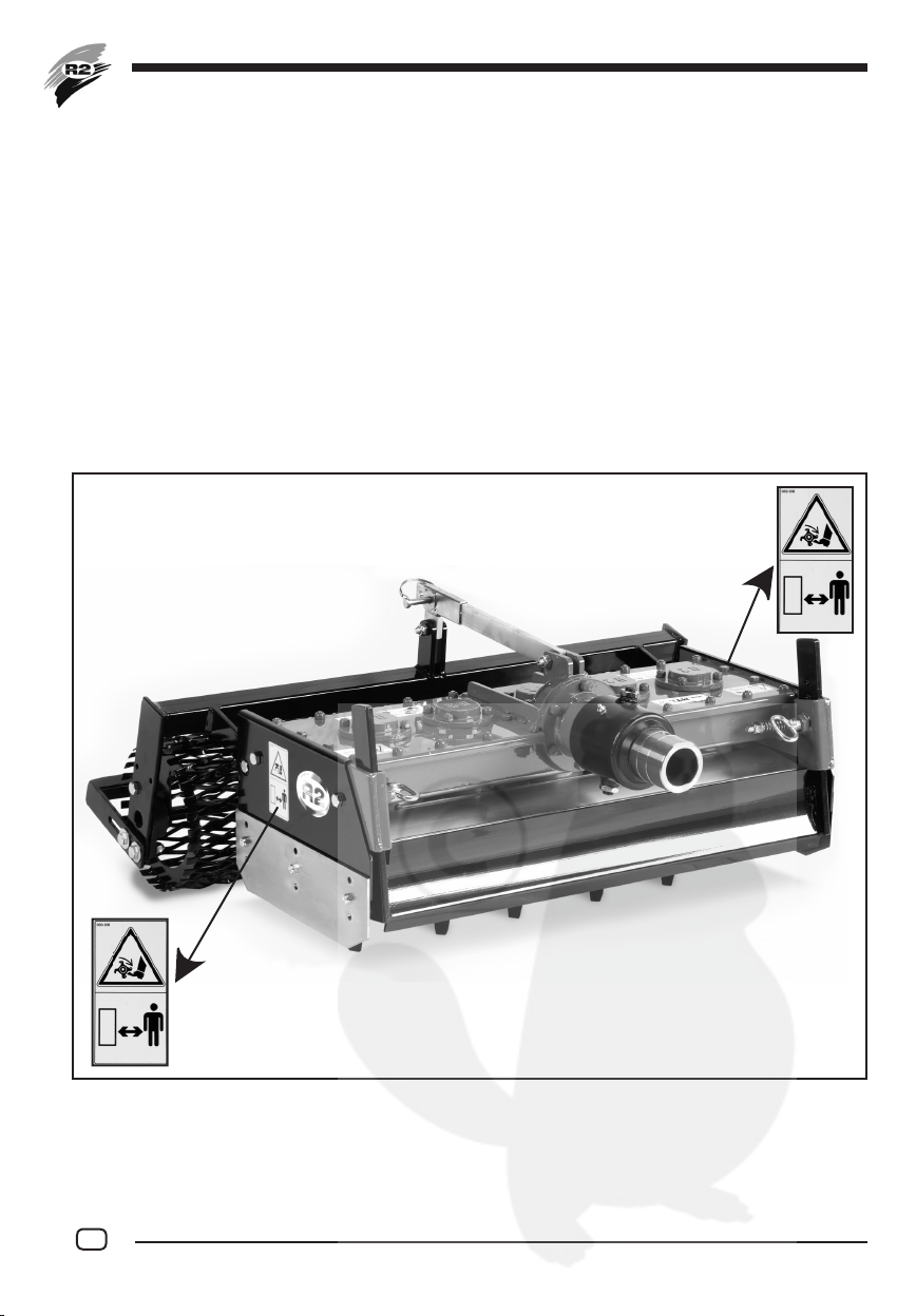
Prevenzione infortuni......................................... 4
Caratteristiche costruttive.................................. 4
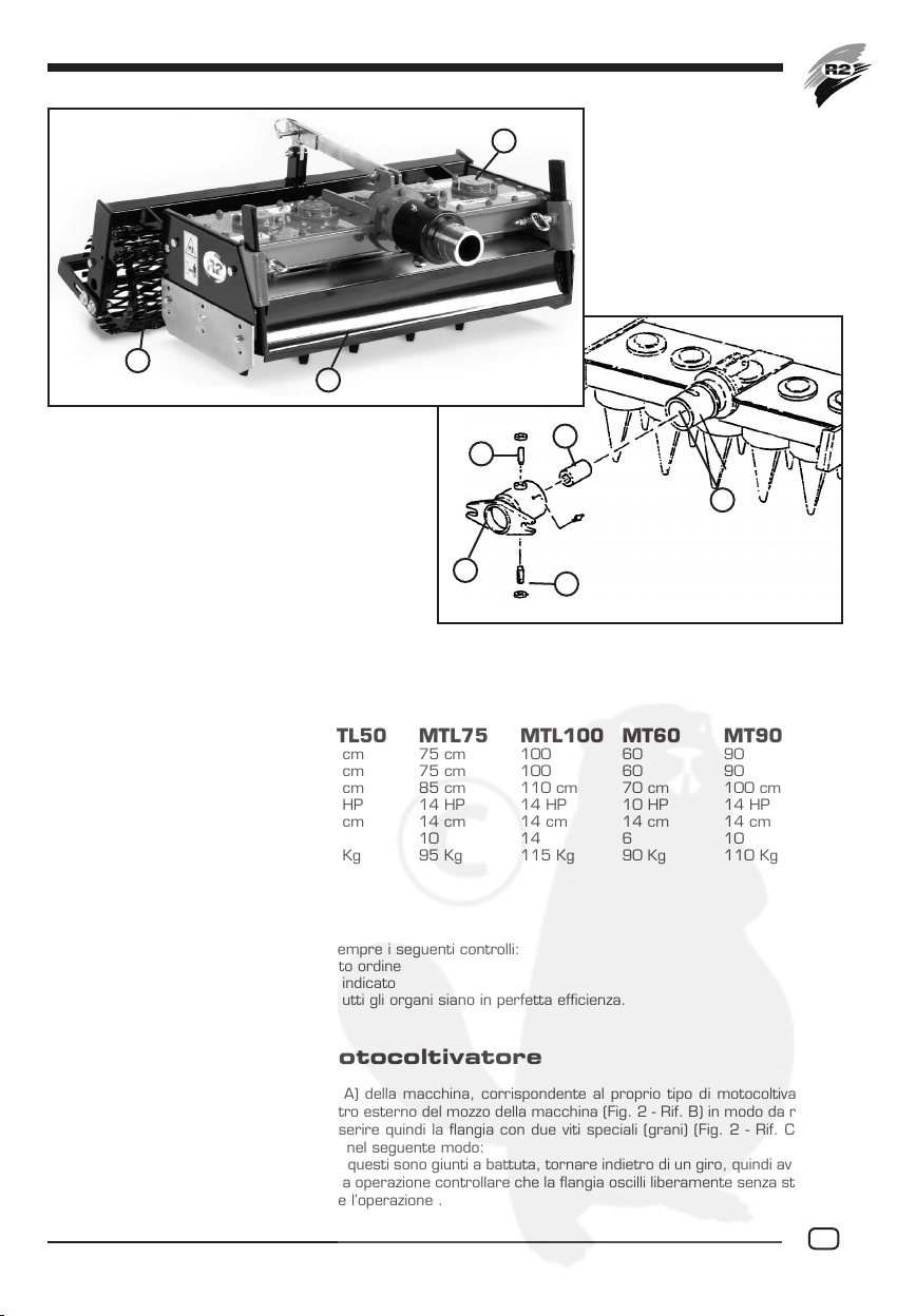
Caratteristiche tecniche..................................... 5
Preparazione all’uso .......................................... 5
Agganciamento al motocoltivatore....................... 5
Regolazione della profondità di lavoro................... 6
Livellazione....................................................... 6
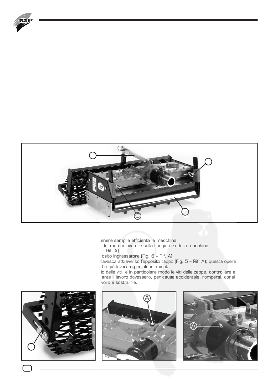
Manutenzione .................................................. 6
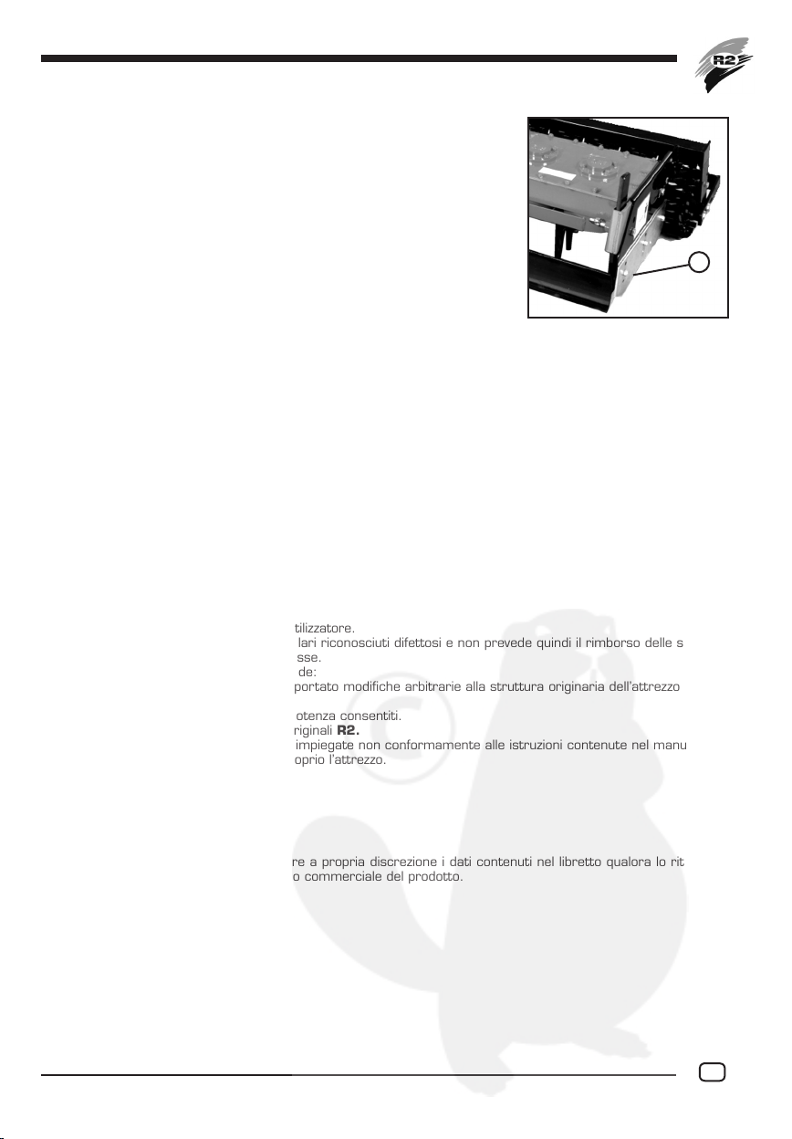
Sostituzione delle zappe ..................................... 7
Fine lavoro....................................................... 7
Garanzia.......................................................... 7
English
Introduction ..................................................... 8
Prevention of accidents .....................................8
Construction features........................................ 8
Technical specications...................................... 9
Preparation before use...................................... 9
Coupling to the engine-driven cultivator................. 9
Regulation of working depth ............................. 10
Levelling ........................................................ 10
Maintenance.................................................. 10
Replacement of hoes....................................... 11
After use....................................................... 11
Guarantee ..................................................... 11
Français
Introduction ................................................... 12
Prévention des accidents de travail.................... 12
Caractéristiques de la construction ...................12
Caractéristiques techniques ............................. 13
Préparation à l’emploi...................................... 13
Attelage au motoculteur ..................................13
Réglage de la profondeur de travail ................... 14
Nivellement.................................................... 14
Entretien ....................................................... 14
Replacement des houes................................... 15
Fin du travail .................................................. 15
Garantie ........................................................ 15
Deutsch
Vorwort ........................................................ 16
Unfallverhütung .............................................. 16
Konstruktionsmerkmale ................................... 16
Technische Eigenschaften ................................ 17
Gebrauchsvorbereitung.................................... 17
Anbau an den Motorkultivator........................... 17
Einstellung der Arbeitstiefe............................... 18
Planierung ..................................................... 18
Wartung ....................................................... 18
Auswechseln der Messer................................. 18
Arbeitsende ................................................... 19
Garantie ........................................................ 19
Español
Introducción................................................... 20
Prevención de accidentes................................. 20
Características de construcción........................ 20
Características técnicas .................................. 21
Preparación para el uso................................... 21
Conexión al motocultivador............................... 21
Regulación de la profundidad de trabajo ............. 22
Nivelación...................................................... 22
Mantenimiento ............................................... 22
Sustitución de las azadas................................. 23
Fin de trabajo................................................. 23
Garantía ........................................................ 23
3

Premessa
Desideriamo innanzi tutto ringraziarLa per la preferenza accordataci, lieti se si dovrà compiacere delle scelta fatta.
Nell’intento di consentire che la FRESA LIVELLATRICE Mod. MT-MTL acquistata possa offrire per lungo tempo
il massimo rendimento La invitiamo a prendere nota scrupolosamente delle norme di uso e manutenzione elencate
in questo manuale.
Il rispetto di esse Le consentirà di prevenire inconvenienti ed infortuni, dovuti a negligenza o a loro inosservanze,
per i quali la nostra società R2 declina n d’ora ogni responsabilità.
Il presente manuale uso e manutenzione è da considerare parte integrante della macchina stessa e pertanto il
presente deve sempre accompagnare la macchina nella vendita, anche nel caso di vendita a terzi.
Conservando questo manuale in luogo sicuro e in buono stato, permetterà a Voi o chi deve utilizzare la macchina,
una consultazione leggibile e completa in ogni momento.
Prevenzione infortuni
La maggior parte degli incidenti che accadono durante il lavoro, la manutenzione e lo spostamento della macchina,
sono dovuti all’inosservanza delle più elementari norme di prevenzione sugli infortuni. É quindi di fondamentale
importanza che tutte le persone abilitate ad usare la macchina (familiari, dipendenti, collaboratori, ecc.), prendano
visione e rispettino scrupolosamente le norme sottostanti e quelle indicate sulle etichette adesive poste sulla mac-
china:
1. Arrestare sempre il motore del motocoltivatore prima di procedere a operazioni di regolazione, manu-
tenzione o pulizia. Prima di ogni operazione è necessario posizionare la macchina sul pavimento o su
supporti ben stabili.
2. La FRESA LIVELLATRICE Mod. MT-MTL è stata costruita per un lavoro preciso. Essa deve sempre
essere in perfetto stato di funzionamento e deve essere riparata unicamente con dei ricambi originali R2.
3. Controllare in particolare modo prima di ogni utilizzazione il serraggio delle viti e dei dadi, specialmente
quelli delle zappe.
4. Allontanare tutte le persone o animali prima della messa in opera della Vostra macchina.
5. Utilizzare particolare prudenza quando si lavora lungo strade o sentieri.
6. Non lasciare funzionare la macchina senza la dovuta sorveglianza.
7. Durante le operazioni di verica o riparazione, assicurarsi che nessuno possa mettere in servizio la
macchina accidentalmente.
8. Indussare indumenti attillati e che non forniscano appigli agli organi in rotazione della macchina.
9. Non salire per nessuna ragione sulla macchina durante la lavorazione.
10. Non interferire con oggetti sulla macchina durante la lavorazione.
11. Non lavorare mai con la macchina senza il rullo posteriore o senza le protezioni predisposte sulla mac-
china al momento della consegna.
12. Per eseguire la regolazione della ruspetta, spegnere sempre il motocoltivatore ed eseguire questa
regolazione in condizioni di assoluta sicurezza.
Caratteristiche costruttive
La FRESA LIVELLATRICE Mod. MT e MTL è l’unica macchina che applicata a tutti i tipi di motocoltivatori di HP
12-14-18 livella, fresa e compatta il terreno in un’unica operazione.
Come si può notare dall’illustrazione (Fig. 1) la FRESA LIVELLATRICE Mod. MT e MTL è dotata nella sua parte
anteriore di una ruspetta registrabile in altezza per lo spostamento del terreno (Fig. 1 - Rif. A), al centro, di un
erpice rotante per la rafnazione del terreno (Fig. 1 - Rif. B) e, nella sua parte posteriore, di un particolare rullo
grigliato (Fig. 1 - Rif. C) che consente di regolare la profondità di lavoro dell’erpice rotante ed a compattare il
terreno.
La FRESA LIVELLATRICE Mod. MT e MTL è particolarmente indicata alla preparazione del suolo per prati, giar-
dini, impianti sportivi, ortaggi e per coloro che hanno la necessità di eseguire un perfetto livellamento del terreno,
anche in piccoli spazi.
4

Caratteristiche tecniche
La FRESA LIVELLATRICE Mod. MT e MTL viene costruita nelle versioni MTL 50 - 75 - 100 e MT 60 - 90
................................................................. MTL50 MTL75 MTL100 MT60 MT90
Lunghezza fresatura........................ 50 cm 75 cm 100 60 90
Lunghezza livellazione ...................... 50 cm 75 cm 100 60 90
Lunghezza compattatura.................. 60 cm 85 cm 110 cm 70 cm 100 cm
Potenza min. richiesta..................... 10 HP 14 HP 14 HP 10 HP 14 HP
Profondità massima di lavoro............ 14 cm 14 cm 14 cm 14 cm 14 cm
Numero zappe ............................... 6 10 14 6 10
Peso............................................. 70 Kg 95 Kg 115 Kg 90 Kg 110 Kg
Preparazione all’uso
Prima di utilizzare la macchina eseguire sempre i seguenti controlli:
- controllare che la macchina sia in perfetto ordine
- controllare che il lubricante sia al livello indicato
- controllare il serraggio dei bulloni e che tutti gli organi siano in perfetta efcienza.
Aggangiamento al motocoltivatore
Prima di applicare la angia (Fig. 2 - Rif. A) della macchina, corrispondente al proprio tipo di motocoltivatore, è
consigliato spalmare del grasso sul diametro esterno del mozzo della macchina (Fig. 2 - Rif. B) in modo da rendere
lubricata l’oscillazione della macchina. Inserire quindi la angia con due viti speciali (grani) (Fig. 2 - Rif. C) e due
dadi; per ssare la angia sul mozzo agire nel seguente modo:
- Avvitare i grani no in fondo e quando questi sono giunti a battuta, tornare indietro di un giro, quindi avvicinare
i dadi e stringere. Al termine di questa operazione controllare che la angia oscilli liberamente senza stringere
o grippare, in caso contrario ripetere l’operazione .
B
A
D
C
C
g.2
g.1
A
B
C
5

Manutenzione
Operazioni da compiere al ne di mantenere sempre efciente la macchina:
1 Controllare il serraggio dei tiranti del motocoltivatore sulla angiatura della macchina
2 Ingrassare i supporti rullo (Fig. 4 – Rif. A)
3 Ingrassare la angia tramite l’apposito ingrassatore (Fig. 6 – Rif. A)
4 Controllare il livello del grasso nellavasca attraverso l’apposito tappo (Fig. 5 – Rif. A); questa operazione deve
essere fatta quando la macchina ha già lavorato per alcuni minuti.
5 Controllare in generale il serraggio delle viti, e in particolare modo le viti delle zappe, controllare anche che
queste siano integre, qualora durante il lavoro dovessero, per causa accidentale, rompersi, consigliamo do
sospendere immediatamente il lavoro e sostituirle.
- Inserire quindi il manicotto di trasmissione (Fig. 2 - Rif. D) sull’albero della macchina avendolo precedente-
mente ingrassato. Quando queste due operazioni sono state eseguite, avvicinare il motocoltivatore alla mac-
china facendo attenzione che il manicotto innesti con l’albero di trasmissione del motocoltivatore e che la
angia sia battuta, quindi stringere la macchina con i tiranti dello stesso motocoltivatore.
Regolazione della profondità di lavoro
La profondità di lavoro viene regolata tramite la spina del supporto rullo (Fig.3 - Rif.A); con questa spina scegliendo
un foro sull’asta si può ottenere una profondità di lavoro che varia da 0 a 14 cm. É importante che durante il lavoro
l’operatore lasci la macchina appoggiata sul suo rullo.
Livellazione
La livellazione viene eseguita tramite la ruspetta anteriore (Fig.3 - Rif.B); la regolazione di questa si esegue in base
alla profondità di lavoro prescelta agendo manualmente sulle due apposite viti speciali (Fig.3 - Rif.C). Per un buon
livellamento accertarsi che in fase di lavorazione di fronte alla ruspetta vi sia sempre del terreno.
N.B. per ruspetta livellatrice si intende un accessorio che trascini del terreno gia smosso da un’altra macchina o
dalla macchina stessa, in caso contrario la ruspetta non farebbe il lavoro per cui era stata destinata ma anzi si
rischierebbe di rovinarla, quindi, quando si esegue una lavorazione su terreni duri, è neccessario alzare tutta la
ruspetta.
A
A
A
g.3
A
C
B
C
g.4 g.5 g.6
6

Sostituzione delle zappe
La sostituzione delle zappe deve essere fatta appoggiando la macchina sul
anco in modo da avere le zappe parallele al terreno.
Nel montaggio delle zappe nuove assicurarsi che il dado di ssaggio sia inserito
bene nella propria sede; consigliamo inoltre di cambiare la serie completa della
bulloneria ogni qual volta le viti stesse siano già rovinate.
N.B. montare sempre bulloneria originale in acciaio con passo ne.
Per il massimo sfruttamento delle zappe la macchina è dotata sulle ancatine
di due prolunghe (Fig. 7 - Rif. A), questo permette di lavorare ancora con le
zappe consumate, tale consumo però non dovrà essere superiore ai 2/3 della
zappa stessa.
N.B. Per motocoltivatori di piccola cilindrata (8-10 CV) controllare che l’altezza
da terra della presa di forza sia almeno 28-30 cm. Se l’altezza è di 25-26 cm
circa è consigliabile accorciare la zappa per rendere la macchina in linea con
il motocoltivatore.
Fine lavoro
Se la FRESA LIVELLATRICE Mod. MT - MTL deve rimanere inattiva per un lungo periodo è necessario eseguire
le seguenti operazioni:
1. Lavare accuratamente la FRESA LIVELLATRICE Mod. MT - MTL e quindi asciugarla.
2. Controllare accuratamente la funzionalità di tutte le parti in movimento e sostituire quelle danneggiate,
deteriorate, o usurate
3. Controllare il serraggio di tutti i bulloni.
4. Controllare il livello del lubricante nella scatola riduttori.
5. Proteggere e lubricare tutte le parti metalliche non verniciate, quindi coprire l’attrezzo e ricoverarlo in
ambiente asciutto. sarà così pronto per l’impiego al momento del riutilizzo.
Attenzione: al momento dell’utilizzo dell’attrezzo, attenersi a quanto contenuto nel capitolo “Manutenzione”.
Garanzia
Le attrezzature di nostra produzione sono coperte da una garanzia per difetti di fabricazione e/o montaggio valida
1 anno dalla data della loro consegna all’utilizzatore.
Essa è limitata alla sostituzione dei particolari riconosciuti difettosi e non prevede quindi il rimborso delle spese di
manodopera e di trasporto ad esse connesse.
Il diritto all’applicazione della garanzia decade:
- Nel caso risulti che l’acquirente abbia apportato modiche arbitrarie alla struttura originaria dell’attrezzo fornito-
gli.
- Nel caso vengano oltrepassati i limiti di potenza consentiti.
- Nel caso non vengano utilizzati ricambi originali R2.
- Nel caso le nostre attrezzature vengano impiegate non conformamente alle istruzioni contenute nel manuale.
- Nel caso l’operatore utilizzi in modo improprio l’attrezzo.
La ditta R2 si riserva il diritto di modicare a propria discrezione i dati contenuti nel libretto qualora lo ritenesse
necessario per un miglioramento tecnico o commerciale del prodotto.
g.7
A
7

Introduction
We would start by thanking you for having chosen our product and hope that you will be happy with your choise.
In order that your MILL GRADER Mod. MT e MTL will serve you well for many years, we ask you to pay attention
to the instructions for use and maintenance which you will nd in this manual. Observance of these regulations will
prevent breakdowns and accidents for which our R2 company will not accept responsability.
This use and maintenance manual is to be considered an integral part of the machine itself and therefore it must
always accompany the machine when it is sold, even in the event of its sale to third parties.
If you keep this manual in a safe place and in good condition, you - and whoever must use the machine - will be able
to have a complete, legible reference on hand at all time.
Prevention of accidents
Most accidents that occur during work, maintenance or the moving of a machine are due to negligence in the
observance of the most elementary rules of accident prevention.
It is, therefore, necessary that all qualied user, (relatives, employees, colleagues) scrupulously read and note the
rules written below and on the adhesive stickers on the machine itself.
1. Turn off the engine-driven cultivator before making any adjustments, carryng out maintenance or clea-
ring. Before any adjustment it is necessary to place the machine on the oor or on rm stands.
Before any adjustments it is necessary to place the machine on the oor or on rm stands.
2. The MILL GRADER Mod. MT e MTL has been manufactured for a specialized use. It must, therefore,
always be in perfect working condition and anly R2 spare parts should be used when making
repairs.
3. It is most omportant that the tightness of the nuts and screws are checked before use, especially those of
t he hoes.
4. Before starting up, make sure that no people or animals are in the vicinity.
5. Take special care when working alongside roads or pathways.
6. Do not leave the tractor running without supervision.
7. During checking or repairing, make sure that nobody can start up the machine accidentally.
8. Close tting garments should be worn in order to avoid getting caught in moving parts.
9. Do not, for any reason, climb into the machine during operation.
10. Do not interfere with any object on the machine during operation.
11. Never use the machine without the back roller or without the protections found on the machine at the
moment of the delivery.
12. When adjusting the grader, always turn off the engine-driven cultivator and carry out such adjustments
in conditions of absolute safety.
Contruction features
The MILL GRADER Mod. MT e MTL is the only machine that can be applied to all types of motor-driven farming
machines with 12-14-18 HP levels, mills and compresses the earth in a single operation.
As can be seen from the illustration (Fig. 1), the MILL GRADER Mod. MT e MTL is equipped with an adjustable
–height scrapper on the front to shift the earth (Fig. 1 – Rif. A), a central rotating harrow to crumble the earth (Fig.
1 – Rif. B), and a special grilled roller at the back (Fig. 1 – Rif. C), which makes it possible to adjust the working
depth of the rotating harrow and to compress the earth.
The MILL GRADER Mod. MT e MTL is especially suitable in preparing the soil for elds, gardens, sporting facili-
ties, vegetable gardens and anyone who needs the ground to be perfectly levelled, also in small spaces.
8

Technical specication
The MILL GRADER Mod. MT e MTL is built in the MTL 50 - 75 - 100 e MT 60 - 90
................................................................. MTL50 MTL75 MTL100 MT60 MT90
Milling length.................................. 50 cm 75 cm 100 60 90
Levelling length............................... 50 cm 75 cm 100 60 90
Compressing length ........................ 60 cm 85 cm 110 cm 70 cm 100 cm
Min. power required........................ 10 HP 14 HP 14 HP 10 HP 14 HP
Max. working depth......................... 14 cm 14 cm 14 cm 14 cm 14 cm
Nr. of hoes .................................... 6 10 14 6 10
Weight.......................................... 70 Kg 95 Kg 115 Kg 90 Kg 110 Kg
Preparation before use
Before starting operation it is necessary to perform following steps:
- Check that the machine is in perfect working order.
- Check that lubricant is at the correct indicated level.
- Check the tightness of the bolts and that all parts are in perfect order.
Coupling to engine-driven cultivator
Before applying the machine ange (Fig. 2 – Rif. A), corresponding to the type of engine-driven cultivator you have,
it is recommended to spread grease on the outer diameter of the machine hub (Fig. 2 – Rif. B) to lubricate machine
oscillation. Then insert the ange with its two special screws (dowels) (Fig. 2 – Rif. C) and two nuts. To attach the
ange to the hub, proceed as follows:
- Screw the two dowels in, as far as they will go; when they have stuck the bottom, unscrew them by one
turn. Move the nuts in and tighten. After this operation, make sure that the ange oscillates freely without
squeezing or blocking; if necessary, repeat the operation.
- Then insert the trasmission sleeve (Fig. 2 – Rif. D) on the machine shaft, after rst greasing it.
B
A
D
C
C
g.2
g.1
A
B
C
9

When these two operations are complete, move the engine-driven cultivator close to the machine, making sure
that the sleeve engages with the trasmission shaft of the cultivator and that the anges touches, then use the
tierods of the cultivator to tighten the machine.
Adjusting the working depth
The working depth is adjusted by means of the roller support pin (g.3 - ref. A). By selecting a hole on the rod in
which to insert this pin, it is possible to vary the working depth from 0 to 14 cm. It is important for the operator
to leave the machine resting on its roller while working.
Levelling
Levelling is performed by the front scraper (g.3 - ref. B); it may be adjusted based on the preset working depth by
manually turning the two special screws (g.3 - ref. C) provided for this purpose. For best levelling results, make
sure that there is always soil in front of the scraper while working.
NOTE: the levelling scraper is an accessory which drags earth already loosened by another machine or the same
machine. If this were not the case, the scraper would be unable to perform the job for which it is built and it could
be ruined. Therefore, when working on hard ground the scraper must be fully raised.
Maintenance
Operations to be carried out in order to maintain the machine in good working conditions:
1) Make sure the tie-rods of the engine-driven cultivator are rmly fastened to the machine ange.
2) Grease the roller support (Fig. 4 – Rif. A)
3) Grease the ange using the special lubricator (Fig. 6 – Rif. A)
4) Check the level of grease in the hub through the cap (Fig. 5 – Rif. A); this operation must be carried out
when the machine has already been running for a few minutes.
5) Generally make sure that all screws are tight, especially the hoe srews. Also make sure that they are
intact; should they accidentally breack while working, we recommend to stop working immediately and
replace them.
A
A
A
g.3
A
C
B
C
g.4 g.5 g.6
10

Replacement of hoes
The hoes must be replaced by resting the machine on its side so that the hoes
are parallel to the ground.
When assembling new hoes, make sure that the xing nut is properly inserted
in its slot. We also recommend to replace the entire set of nuts and bolts each
time the screws are worn (NOTE: always use the original, ne-pitch steel nuts
and bolts).
To take maximum advantage of the hoes, the machine has two extensions (Fig. 7 -
Ref. A) on the sides making it possible to work even with worn hoes; they must not
be worn for over 2/3 of the hoe length.
NOTE: For small-displacement cultivators (8-10 HP), make sure that the power take-
off is at least 28-30 cm off the ground. If the height is instead apporximately 25-26
cm, it is recommended to shorten the hoe in order to align the machine with the cul-
tivator.
After use
If the MILL GRADER Mod. MT e MTL is to remain unused for a long period, it is necessary to carry out the
following instructions:
1. Thoroughly wash and dry the MILL GRADER Mod. MT e MTL.
2. Thoroughly check the working of the moving parts, replacing any damaged, worn or deteriorated
parts.
3. Check the tightening of the bolts.
4. Check the lubricant level in the reduction casing.
5. Protect and lubricate all unpainted parts, cover the tool and keep it in a dry place so that it will be ready
for use at any time.
Attention: before using it again, refer to the “Maintenance” chapter.
Guarantee
our equipment is coveres by guarantee against manufacturing and/or assembly defects for 1 year from the date
of delivery to the customer.
This guarantee in limites to the replacement of defective parts and does not include costs or transport.
This guarantee does not cover the following cases:
- Where the user has made adaptations to the original structure.
- Where the machine has been used in excess of its power limits.
- Where R2 spare parts are not used.
- Where the equipment is not used in accordance with the instructions in the manual.
- Where the equipment has been used incorrectly.
The R2 Company reserves the right to modify the data in this manual whenever this is considered necessary for
technical or commercial improvements regardind the product itself.
g.7
A
11

Introduction
Avant tout voudrions remercier pour la préférence que vous avez nous accordé, heureux si vous serez satisfait de
votre choix.
An que la FRAISE NIVELEUSE Mod. MT - MTL que vous avez acheté puisse vous offrir les meilleures perfor-
mances pendant un long temps, nous vous invitons à lire scrupuleusement lesinstructions d’emploi et d’entretien
contenues dans le présent manuel.
Les respect de ces règles vous permettra d’éviter les inconvénients et les accidents dûs à la negligence ou au
manque de respect de ces règles, pour lesquels notre société R2 décline toute responsabilité. Ce manuel d’utili-
sation et d’entretien doit être considéré comme partie intégrante de la machine, c’est pourquoi il doit toujours
accompagner la machine lors de sa vente même en cas de vente à des tiers. Gardez ce manuel en lieu sûr et en
bon état, il consentira à ceux qui utilisent la machine, une consultation lisible et complète à tous moments.
Prévention contre les accidents de travail
La plupart des accidents qui se produisent pendant le travail, l’entretien et le déplacement de la machine sont dûs
à l’inobservance des règles les plus élémentaires de prévention des accidents. Il est donc de première importance
que toutesles personnes autorisées à utiliser la machine (parents, employés, collaborateurs) respectent scrupu-
leusement les normes suivantes et les indications qui gurent sur les étiquettes adhésives collées sur la machine.
1. Arrêter toulours le moteur du motoculteur avant de procéder à des opération de réglage, d’entretien ou
de nettoyage.
2. La FRAISE NIVELEUSE Mod. MT - MTL a été construite pour un travail précis. Elle doit être contam
ment en parfait état de fonctionnement et doit être réparée seulement avec pièces d’origine R2.
3. Avant chaque utilisation contrôler que le vis et l’écrous soient bien serrés, tout spécialement ceux des
houes.
4. Eloignez toute personne ou animal avant de commencer à travailler.
5. Faire perticulièrement attention quand on travaille le long des routes ou des sentiers.
6. Ne laisser pas marcher la machine sans la surveiller.
7. Pendant les opérations d’entretien ou de réparation, veillez à ce que personne ne puisse mettre la
machine en route accidentellement.
8. Portez toulours des vêtements collants qui ne puissent en tout cas être accrochés par les organes en
rotation de la machine.
9. Ne montez en aucune cas sur la machine pendant son fonctionnement.
10. N’interférez pas sur la machine avec des objets quels qu’ils soient pendant son fonctionnement.
11. Ne jamais utiliser la machine sans le rouleau arrière ou sans les protections prévues sur la machine au
moment de sa livraison.
12. Pour effectuer le réglage de la petite niveleuse, éteignez toujours le motoculteur et procédez à ce
réglage dans des conditions de sécurité absolue.
Caractéristiques de la construction
La FRAISE NIVELEUSE mod.MT e MTL est la seule machine qui, appliquée à tous les types de motoculteurs de
12-14-18 HP, est en mesure d’égaliser, de fraiser et de compacter le sol en une seule opération.
Comme le montre l’illustration (Fig.1), la FRAISE NIVELEUSE mod.MT e MTL est équipée à l’avant d’une
décapeuse réglable en hauteur pour ameublir la terre (Fig.1 – Réf.A), au milieu d’une herse rotative pour afner la
terre (Fig.1 – Réf.B) et à l’arrière d’un rouleau spécial à grille (Fig.1 – Réf.C) permettant de régler la profondeur
de travail de la herse rotative et de compacter la terre.
La FRAISE NIVELEUSE mod.MT e MTL est particulièrement indiquéepour la préparation du sol en cas
d’aménagements de pelouses, installations sportives, cultures maraîchères et lorsqu’il faut obtenir un nivellement
parfait du sol, y compris sur un espace restreint.
12

Caractéristiques techniques
La FRAISE NIVELEUSE Mod. MT - MTL existe dans les versiones MTL 50 - 75 - 100 e MT 60 - 90
................................................................. MTL50 MTL75 MTL100 MT60 MT90
Longueur de labour......................... 50 cm 75 cm 100 60 90
Longueur nivellement ...................... 50 cm 75 cm 100 60 90
Longueur compactage..................... 60 cm 85 cm 110 cm 70 cm 100 cm
Puissance min. demandée ............... 10 HP 14 HP 14 HP 10 HP 14 HP
Profondeur max. de travail ............... 14 cm 14 cm 14 cm 14 cm 14 cm
Nombre de houes........................... 6 10 14 6 10
Poids ............................................ 70 Kg 95 Kg 115 Kg 90 Kg 110 Kg
Préparation a l’emploi
Avant l’utilisatio de la machine effectuer toujours les contrôles suivants:
- Contrôler que la machine soit en perfait condition
- Contrôler que le lubriant soit au niveau indiqué
- Contrôler le serrage des boulons et que tous les organes soient en parfait état de marche.
Attelage au motoculteur
Avant d’appliquer le asque (Fig.2 – Réf.A) de la machine correspondant au motoculteur utilisé, il est conseillé
d’étaler une couche de graisse sur le diamètre extérieur du moyeu de la machine (Fig.2 – Réf.B) de manière à
lubrier l’oscillation de la machine. Monter alors le asque avec ses deux vis sans tête (Fig.2 – Réf.C) et ses deux
écrous. Pour xer le asque sur le moyeu, effectuer les opération ci-dessous:
- visser à fond le vis; lorsque cette opération, vérier si le asque oscille bien librement sans serrer ni gripper. En
cas de besoin refaire l’opération;
- monter ensuite le manchon de transmission (Fig.2 – Réf.D) sur l’arbre de la machine, non sans l’avoir graissé
auparavant. A la n de ces deux opération, rapprocher le motoculteur de la machine. Veiller à ce que le manchon
se monte bien sur l’arbre de transmission du motoculteur et que le asque arrive bien en battue. Serrer alors à
l’aide des tirants du motoculteur.
B
A
D
C
C
g.2
g.1
A
B
C
13

Réglage de la profondeur de travail
La profondeur de travail est réglée par l’intermédiaire du levier de réglage du rouleau (Fig.1 - Réf.B); il est ainsi
pobbible d’obtenir une profondeur de travail allant de 0 à 14 cm. Il est important que lorsque la machine est en
service, l’opérateur laisse la machine posée sur son roleau.
Nivellement
Pour la mise à niveau utiliser la décapeuse avant (Fig.3 - Réf.B). Régler cette dernière en fonction de la profondeur
de travail choisie, en faisant tourner à la main les deux vis spéciales (Fig.3 - Réf.C). Pour une mise à niveau
correcte il doit toujours y avoir de la terre devant la décapeuse lors du fonctionnement.
N.B. Le terme décapeuse-niveleuse désigne un accessoire entraînant de la terre déjà déplacée par une autre
machine ou par la machine elle-même. Dans le cas contraire, la machine n’accomplirait pas le travail pour lequel
elle à été conçue, elle risquerait même de s’abîmer. En présence d’un terrain dur il est donc nécessaire de remon-
ter toute la décapeuse.
Entretien
Voici la liste des opération à effectuer pour conserver à la machine toutes ses performances:
1 Contrôler le serrage des tirants du motoculteur sur la bridage de la machine
2 Graisser les supports du rouleau (Fig.4 – Réf.A).
3 Graisser la asque à l’aide du graisseur prévu à cet effet (Fig.6 – Réf.A).
4 Contrôler le niveau de la graisse dans la curve à travers le bouchon (Fig.5 – Réf.A); cette opearation
doit être faite lorsque la machine a déjà fonctionné quelques minutes.
5 Contrôler d’une manière générale le serrage des vis, notamment les vis des houes; ces dernières
doivent être en parfait état. Si pour une raison accidentalle elles se caissent au cours du travail,
interrompre les opération et les remplacer.
A
A
A
g.3
A
C
B
C
g.4 g.5 g.6
14

Replacement des houes
Pour remplacer les houes, il faut poser la machine sur le côté, de manière à
ce que les houes soient parallèles au sol.
Lors du montage de pièces neuves, vérier si l’écrou de xation est bien enlé
dans son siège. Il est également conseillé de remplacer le jeu complet des
boulons chaque fois que les vis ont été abîmées.
N.B. ne monter que des boulons originaux en acier à pas n).
Pour exploiter au mieux les houes, la machine est équipée sur le côté de deux
rallonges (Fig. 7 - Ref A). Ceci permet de travailler encore lorsque les houes
sont usées. Toutefois, cette usure ne doit pas dépasser les 2/3 de la houe.
N.B. Sur les motoculteurs de petite cylindrée (8-10 HP), contrôler si l’hauteur
de la prise de force à partir du sol dépasse bien 28-30 cm. Si cette hauteur
atteint 25-26 cm environ il est conseillé de raccoucir l’houe pour aligner la
machine par rapport au motoculteur.
Fin travail
Si la FRAISE NIVELEUSE mod.MT e MTL doit rester inactive pendant une longue période il est nécessaire
d’exécuter les opération suivantes:
1. Laver soigneusement la FRAISE NIVELEUSE mod.MT e MTL et ensuite l’essuyer.
2. Contrôler soigneusement le parfait état de toutes les parties en mouvement et remplacer celles qui
sont endommagées, détériorées ou usagées.
3. Contrôler le serrage de tous les boulons.
4. Contrôler le niveau de lubriants dans la boîte des réducteurs.
5. Protéger et lubrier les parties métalliques sans peinture, ensuite couvrir l’appareil et le tenir a l’abri
de l’humidité, de manière qu’il soit prêt à l’emploi un moment de sa réutilisation.
Attention: avant de réutiliser l’appareil se conformer aux instuctions contenues dans le chapitre “Entretien”.
Garantie
Les appareils de notre production sont couverts par une garantie pour dèfauts de fabrication et/ou de montage
valable 1 année à partie de leur livraison à l’utilisateur.
Elle est limitée au remplacement de pièces reconnues défectueuses et elle ne prévoit donc pas le remboursement
des frais de main d’oeuvre et de transport relatifs.
Le droit à la garantie n’est pas reconnu lors que:
- Il résulte que l’acheteur a apporté des modications arbitraire à la structure originale de l’appareil qui lui a été
fourni.
- Ont été dépassés les limites de puissance admises.
- N’ont pas été utilisées les pièces de rechange d’origine R2.
- Nos appareil n’ont pas été emplyés en conformité avec les instructions contenues dans nos manuels.
- L’opérateur utilise l’appareil d’une manière inconvenable.
Toujours soucieux d’améliorer ses productions, R2 se réserve le droit de modier sans préavis les caractéristiques
et les données des matériels présentés dans ce document.
g.7
A
15

Vorwort
Zunächst bedanken wir uns für Ihr Vertrauen in uns und hoffen, Sie sind mit Ihrer Wahl zufrienden.
Um sicherzustellen, daß die von Ihnen erworbene PLANIERFRÄSE Mod. MT - MTL auf lange Sicht optimale Lei-
stungen bietet, empfehlen wir, die hier dargestellten Anwendungs-und Wartungsanleitungen genau zu beachten.
Auf diese Weise lassen sich Schäden und Unfälle vermeiden, die bei Nichtbeachtung dieser Hinweise eintreten
können, und für die unsere Firma R2 keine Haftung übernimmt.
Das vorliegende Gabrauchs-und Wartungsbuch versteht sich als wesentlicher Maschinenbestandteil und muß
daher stets im Verkauf der Maschine inbegriffen sein, auch beim Verkauf an Dritte.
Bewahren Sie dieses Handbuch gut und sicher auf, es dient Ihnen bzw. dem Benutzer der Maschine jederzeit als
gut lesbares und umfassendes Nachschlagewerk.
Unfallverhütung
Die meisten Unfälle, die bei Gebrauch, Wartung und Verlegung der Maschine entstehen, beruhen auf der Nicht-
beachtung grundlegender Unfallverhütungsnormen. Es ist daher besonders wichtig, daß alle zur Anwendung der
Maschine zugelassenen Personen (Familienmitglieder, Angestellte, Mitarbeiter, usw.) die im Folgenden aufgef¨hrten
Vorschriften, sowie die auf den Klebeetiketten an der Maschine angezeigten Hinweise zur Kenntnis nehmen und
sorgfältig beachten:
1. Vor dem Einstellen, Warten bzw. Reinigen immer zuerst den Motor des Kultivators abstellen.
2. Die PLANIERFRÄSE Mod. MT - MTL ist für eine bestimmte Arbeit entwickelt worden. Sie muß stets in
einwandfreiem Zustand sein, und Reparaturen sind nur mit R2 - Originalersatzteilen auszuführen.
3. Vor jeder Anwendung vor allem darauf achten, daß alle Schrauben und Muttern, besonders an den
Zinken, einwandfrei angezogen sind.
4. Alle Personen und Tiere vor Inbetriebsetzen Ihrer Maschine in Sicherheitsabstand halten.
5. Bei Arbeiten an Straßen und Wegen mit besonderer Vorsicht vorgehen.
6. Die Maschine nie ahne Aufsicht in Betrieb lassen.
7. Bei Kontroll-bzw Reparationsarbeiten darauf acheten, daß niemand die Maschine zufällig in Betrieb setzen kann.
8. Angliegende Kleidung tragen, die nicht von der in Rotation stehenden Maschine erfaßt werden kann.
9. Niemals während der Arbeit auf die Maschine steigen.
10. Nicht mit Gegentänden auf die in Betrieb Maschine einwirken.
11. Mit der Maschine nie ohne hintere Walze, bzw. ohne die bei Maschinenlieferung vorhandenen Schutzvor-
richtungen arbeiten.
12. Zum Einstellen des Planierschilds den Motorkultivator abstellen und unter Beachtung aller Sicherheitsbe-
dingungen arbeiten.
Konstruktionsmerkmale
Die PLANIERFRÄSE Mod. MT – MTL läßt sich an alle Typen von Motorkultivatoren mit 12-14-18 PS anbauen
und ebnet, fräst und kompaktiert den Boden als einzige Maschine in nur einem Arbeitsgang.
Wie die Abbildung zeigt (Fig. 1), ist die PLANIERFRÄSE Mod. MT – MTL an der Vorderseite mit einem Pla-
nierschild ausgestattet, das je nach Höhe des zu bewegenden Erdreichs einstellbar ist (Fig. 1, Punkt A), in der
Mitte mit einer Kreiselegge zur Bodenverfeinerung (Fig. 1, Punkt B), und an der Rückseite mit einer besonderen
Gitterwalze (Fig. 1, Punkt C), mit der die Arbeitstiefe der Kreiselegge geregelt werden kann, und die den Boden
kompaktiert.
Die PLANIERFRÄSE Mod. MT – MTL ist besonders geeignet zur Bondervorbereitung für Rasen und Gärten,
Sportanlagen, Gemüseanbauächen und für jede Art von perfekter Bodenbnung, auch auf kleinem Raum.
16

Technische eigenschaften
Die PLANIERFRÄSE Mod. MT - MTL wird hergestellt in den versionen MTL 50 - 75 - 100 e MT 60 - 90
................................................................. MTL50 MTL75 MTL100 MT60 MT90
Fräslange ...................................... 50 cm 75 cm 100 60 90
Planierlänge................................... 50 cm 75 cm 100 60 90
Kompaktierlänge............................. 60 cm 85 cm 110 cm 70 cm 100 cm
Erforderliche Leistungsstärke, mind... 10 HP 14 HP 14 HP 10 HP 14 HP
Maximale Arbeitstiefe...................... 14 cm 14 cm 14 cm 14 cm 14 cm
Anzahl der Zinken ........................... 6 10 14 6 10
Gewicht......................................... 70 Kg 95 Kg 115 Kg 90 Kg 110 Kg
Gebrauchsvorbereitung
Vor Anwendung der Maschine stets folgendes beachten:
- Sicherstellen, daß die Maschine in perfektem Zustand ist.
- Darauf achten, daß das Schmiermitteln der vorgeschriebenen Höhe entspricht.
- Kontrollieren, daß die Schraubn richtig angezogen und alle Teile betriebsbereit sind.
Anbau an den motorkultivator
Vor Anbringen des dem jeweiligen Motorkultivator entsprechenden Maschinenanschs (Fig. 2, Punkt A) empehlt
es sich, den Kopfkreisdurchmesser der Maschinennabe einzufetten (Fig. 2, Punkt B), um dieMaschinenschwin-
gung geschimiert zu halten. Dann den Flansch mit den beiden Spezialschrauben (Stifte) (Fig. 2, Punkt C) und den
beiden Muttern einsetzen. Zum Befestigen des Flasches an der Nabe folgendermaßen vorgehen:
- Die Stifte biszum Anschlag festschrauben, dann um eine Drehung zurückdrehen und die Muttern festschrauben.
Darauf achten, daß sich der Flansch unbehindert bewegen läßt. Andernfalls den Arbeitsgang wiederholen.
- Als nächstes die Antriebsmuffe (Fig. 2, Punkt D) in die vorher eingefettete Maschinenewelle einführen. Dann den
Motorkultivator nahe an die Maschine heranführen und darauf achten, daß sich die Muffe mit der Getriebewelle
des Motorkultivators verkuppelt, und daß sich der Flansch im Aschlag bendet. Dann die Maschine mit den Zugbol-
zen des Motorkultivators festziehen.
B
A
D
C
C
g.2
g.1
A
B
C
17

Wartung
Für eine stets einsatzbereite Maschine folgende Arbeitsgänge ausführen:
1 Kontrollieren, ob die Zugbolzen des Motorkultivators auf dem Maschinenansch angezogen sind.
2 Die Wanzenhalterung schmieren (Fig. 4, Punkt A).
3 Den Flansch mit Hilfe des vorgesehenen Schmiernippels einfetten (Fig. 6, Punkt A).
4 Das Schmiermittelniveau in dem Behälter durch den vorgesehenen Schraubstöpsel nachsehen (Fig. ,
Punkt A). Dies sollte nach einigen Minuten Betriebstätigkeit erfolgen.
5 Generell den Schraubenanzug kontrollieren, besonders die Schrauben der Zinken. Auch darauf achten,
daß sie unversehrt sind. Sollten sie während der Arbeit beschädigt werden, empfehlen wir, sie bei
sofortiger Arbeitsunterbrechung auszuwechseln.
Einstellung der Arbeistiefe
Die Arbeistiefenregelung erfolgt mit dem Stift der Walzenhalterung reguliert (Fig.3 - Punkt A); Je nach Einführen
des Stifts in eines der Löcher auf dem Halterungsstab wird die Arbeitstiefe von 0 bis 14 cm. Wichtig ist, daß
während der Arbeit die Maschine auf der Walze auiegen.
Planierung
Die Planierung erfolgt mit dem vorderen Planierschild (Fig.3 - Punkt B). Es läßt sich je nach gewählter Arbeitstiefe
mit den beiden vorgesehenen Spezialschrauben einstellen (Fig.3 - Punkt C). Zur Gewährleistung einer guten planie-
rung darauf achten, daß sich bei der Arbeit Erdreich vor dem Planierschild bendet.
N.B.: Unter Planierschild versteht sich ein Zusatzteil, daß die bereits von der gleichen oder einer anderen
Maschine gelockerte Erde weiterbewegt. Andernfalls würde das Planierschild seinen Verwendungszweck nicht
erfüllen und könnte beschadigt werden. Daher bei Bearbeitung harter Böden das gesamte Planierschild vom
Boden abheben.
A
A
A
g.3
A
C
B
C
g.4 g.5 g.6
18
This manual suits for next models
4
Table of contents
Languages:
Other R2 RINALDI Tractor Accessories manuals
Popular Tractor Accessories manuals by other brands

MRF
MRF BS96 Operator's manual

Soucy
Soucy S-TECH 7016 Installation, operation and maintenance guide

Bercomac
Bercomac BERCO 700272-2 owner's manual

Avantco
Avantco A440199 Operator's manual for Attachment

Honeybee
Honeybee AirFlex 225 Operator's manual

Avantco
Avantco Collecting broom 1100 Operator's manual for Attachment