Racepak IQ3 Drag Dash User manual

IQ3 Street Dash Installation Manual
1
IQ3 Street Dash
Installation Manual
IQ3 Street Dash Manual Final Rev
B
Racepak, IQ3 Street Dash and V-Net are trade arks of Racepak LLC.
© Racepak LLC

IQ3 Street Dash Installation Manual
2
Disclaimer
Racepak LLC akes no representations or warranties of any type with respect to the contents in
this anual. Racepak LLC disclai s any i plied warranties or fitness for any particular purpose.
Racepak LLC is not liable for any errors contained within or for incidental or consequential
da ages in connection with the supply, perfor ance or use of the hardware and software or
this anual.
Racepak LLC reserves the right to revise this installation and user anual at any ti e, without
obligation to notify any person of revisions. As defined by the Magnuson-Moss warranty Act, do
not install any parts or services unless you have the technical ability to properly set-up the
entire vehicle to co pensate for the installation of those parts. The necessary work and
expertise needed to install different products varies. Instructions, where provided, are given to
assist in the installation only; they are not a substitute for echanical experience in setting up
vehicles. Racepak LLC is not responsible for any personal or property da ages caused by the
installation of this product.
Warranty
Racepak LLC akes every effort to ensure our products and services are of the highest quality
and standards. It is our intention to aintain a utually beneficial and cordial relationship with
each and every custo er.
Racepak LLC warrants all erchandise anufactured by Racepak LLC against defects in
work anship or aterial for a period of six (6) onths after the date of purchase. This
warranty applies to the first retail purchaser and covers only those products exposed to nor al
use or service. It does not apply to those products used for a purpose for which said products
were not designed, or which has been altered in any way that would be detri ental to the
perfor ance or life of the product, or isapplication, isuse, negligence, or accident. Any part
or product found to be defective after exa ination by Racepak LLC will be repaired or replaced.
Racepak LLC assu es no responsibility for diagnosis, re oval and/or installation labor, loss of
vehicle use, loss of ti e, inconvenience or any other consequential expenses.
This warranty is in lieu of any other expressed or i plied warranties, including any i plied
warranty or erchantability or fitness, and any other obligation on the part of Racepak LLC, or
selling dealer.
If you have any questions regarding warranty, please contact custo er service at Racepak LLC.
949-709-5555
Installation of this product may void factory warranty as dealer may wish to verify
mileage/codes/service hours etc. on factory gauge. Install at your own risk. Factory
gauge may be retained and connected for use as a diagnostic tool.

IQ3 Street Dash Installation Manual
3
Disclai er ............................................................................................................... 2
Warranty................................................................................................................. 2
Manual Su ary .................................................................................................... 5
Manual Quick View .................................................................................................................................................... 5
Ite s Included with the IQ3 Street Dash Display Kit ................................................................................................. 5
IQ3 Street Dash Features ........................................................................................ 6
General Feature Overview ......................................................................................................................................... 6
IQ3 Street Dash Displayed Features .......................................................................................................................... 7
Technical Specifications ............................................................................................................................................. 8
IQ3 Street Dash Functions ......................................................................................................................................... 9
PC Mini u Require ents ...................................................................................................................................... 9
DataLink Progra ing Software ............................................................................................................................... 9
IQ3 Street Dash Configuration File (software)........................................................................................................... 9
Hardware Features ............................................................................................... 10
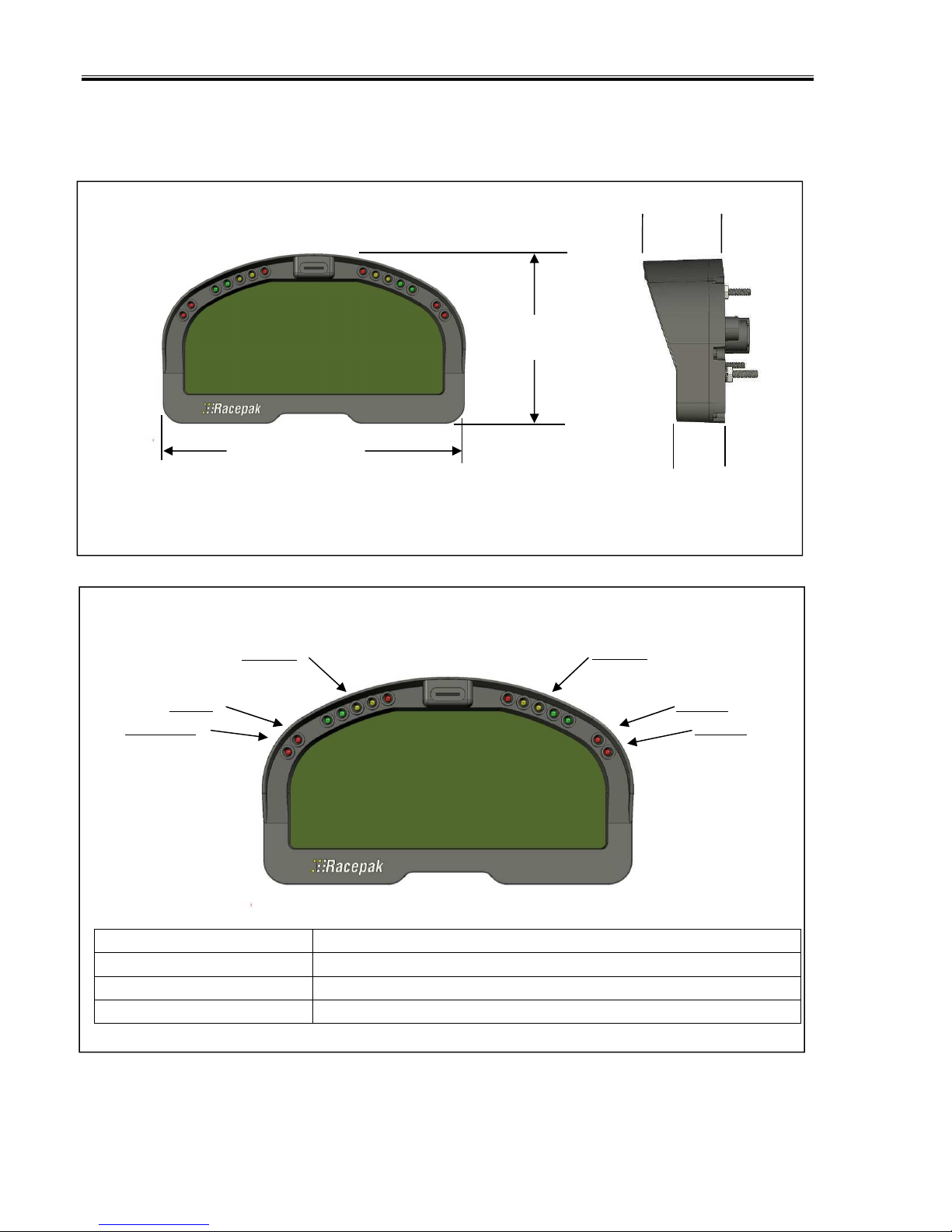
External Di ensions ................................................................................................................................................ 10
External Features – Front ........................................................................................................................................ 10
External Features – Rear.......................................................................................................................................... 11
Mounting Di ensions ............................................................................................................................................. 11
Installation ............................................................................................................................................................... 13
General Mounting Require ents ............................................................................................................................ 13
IQ3 Street Dash Wiring Pinout .............................................................................. 14
External V-Net Sensor Connection (optional add ons) ........................................................................................... 17
Factory Default Display Settings............................................................................ 19
External Progra ing Buttons ............................................................................. 21
Button Progra ing Modes ................................................................................................................................... 21
General Button Operation ....................................................................................................................................... 21
Button Functions in Nor al Display ........................................................................................................................ 22
Button Functions in Setup Mode ............................................................................................................................. 22
Progra ing in Setup Mode .................................................................................................................................. 22
Oil Pressure, Water and Trans ission Te perature Sensor Installation: ............................................................... 28
Fuel Level ................................................................................................................................................................. 29
Speedo eter Sensor Interface ................................................................................................................................ 31
Display Clock/Ti e: ................................................................................................................................................. 32
OBDII and EFI Interface: ........................................................................................ 33
DatalinkII Software Installation ............................................................................. 35
Configuration Files ................................................................................................ 36
Stand Alone or with V-Net Sensors, No External Data Recorder ............................................................................. 36

IQ3 Street Dash Installation Manual
4
IQ3 Street Dash with Data Recorder ....................................................................................................................... 37
Progra ing the Display Using the DataLink Software ........................................ 39
Co Port Settings ................................................................................................................................................... 39
Reading/Syncing of the Configuration File ............................................................................................................. 40
EFI Interface Progra ing ..................................................................................................................................... 41
Progra ing the Display Pages ............................................................................................................................. 43
Progra ing the Warnings .................................................................................................................................... 45
Troubleshooting and FAQ ..................................................................................... 49
DataLink will not co unicate with the IQ3 Street Dash when using the USB progra ing cable..................... 49
V-Net Sensor Channels “lock up” fro ti e to ti e .............................................................................................. 49
Conclusion ............................................................................................................ 50

IQ3 Street Dash Installation Manual
5
Manual Summary
This anual akes the assu ption that you have installed the ost current version of the
DataLink PC software and IQ3 fir ware. IQ3 Street Dash fir ware and DataLink updates can be
found at http://www.racepak.co /downloads. As of this writing, the ost current DataLink
version is 4.6.0 and the ost current IQ3 Street Dash fir ware version is 2.5.
Manual Quick View
The following provides a quick view of the anual layout:
1. IQ3 Street Dash Features
a. Dash
b. Available channels for display
c. External optional sensors
d. Technical specifications
2. Installation
a. Dash
b. Software
3. Progra ing The Display
4. Adding Sensors
5. Software Usage
Items Included with the IQ3 Street Dash Display Kit
Qty. Part Number Description
1 250-DS-IQ3S IQ3 Street Dash Display Kit (incls. all below ite s)
1 280-CA-IQ3S Harness/Street Dash Interface
1 280-CA-VM-TCAPM V-Net Male Ter inator Cap
1 890-CA-USBABM-6 USB Progra ing/Co unication Cable
1 810-PT-0100SD Sensor, analog pressure 0-100 psi
2 810-TR-250 Sensor, analog single wire te perature 0-250°F
1 890-DR-USB-1GB DataLink Software Me ory Stick
2 800-SW-PSHBTN Mo entary Style Push Buttons, spade ter inal
1 N/A Installation Manual

IQ3 Street Dash Installation Manual
6
IQ3 Street Dash Features
The IQ3 Street Dash is a fully progra able LCD digital display dash that displays infor ation
to the user. It does not have a built-in data logger or accelero eters. It can be used as a
standalone unit or with any Racepak V-Net capable data logger, such as the G2X, G2XPro and
V300SD. All seg ents will light up for 1 second at power up.
General Feature Overview
28 Progra able Ite s on 4 pages
Internal Progressive Shift Light LEDs
4 User Progra able Internal Warning Light LEDs with On-Screen Text Warning
5 Character Progra able Alpha/Nu eric Text per Display Channel
Rear Mounted Power/Ground/Street Dash Adapter/Progra ing Buttons Input
Rear Mounted V-Net Sensor Connector
Polarized and Shielded, Anti-Glare Coated Display For Sunlight Viewing
Metric and English (SAE) Capable
Di able Blue Backlight
Gear Position Indicator
Clock / Ti e Keeper
2 Re ote Switch Inputs (Toggle Pages, Acknowledge Warnings, Basic Setup Para eters)
External Shift Light Output (750 A Max Ground Triggered)
External Warning Light Output (750 A Max Ground Triggered)
Cooling Fan Output to Trigger Fan Relay (Relay required, 750 A Max Ground Triggered)
CAN bus for OBDII or 3
rd
Party ECU’s Interface
16 Additional Sensor Inputs via V-Net (CAN bus)
USB Port for DataLink Co unication
Co patible with Racepak Data Loggers

IQ3 Street Dash Installation Manual
7
IQ3 Street Dash Displayed Features
Using the supplied co ponents in the kit, data fro the factory engine control unit (via the
ain harness connection) can be acquired for display purposes on the IQ3 Street Dash. Below is
a list of that infor ation that is available to the end user.
Engine RPM
Speedo eter
Engine Coolant Te perature
Oil Pressure
Oil Te perature
Trans ission Te perature
Fuel Level
Left/Right Turn Signal Indicator
Parking Brake Indicator
High Bea Indicator
Internal Progressive Shift Light LEDs
4 Internal Warning Light LEDs
Clock / Ti e Keeper
Gear Position (indicates gear position, center display position only)
Battery Voltage (Internal)

IQ3 Street Dash Installation Manual
8
Technical Speci ications
otal Sensor Channels - Defined Below 28
Available V-Net Data Channels (optional additions) 16
Internal Channels as Defined Below 1
IQ3 Internal Channel Voltage
Processor Speed 20MHz
Power & Current
Input Voltage 9-18V
Current Draw 350 A - Without warning and shift
LED’s active
Reverse Voltage Protection Yes
Operating emperature 32 - 140°F / 0-60°C
Mounting Orientation Rear of dash facing direction of
travel

IQ3 Street Dash Installation Manual
9
IQ3 Street Dash Functions
The IQ3 Street Dash is the ain co ponent of the syste , as it contains the ain
co unication odule.
PC Minimum Requirements
Windows® XP / Vista / 7 / 8 / 10 operating syste
USB 2.0 Port/ 1024 x 768 or higher onitor resolution
DataLink Programming So tware
The DataLink software is used to both set up and configure the IQ3 Street Dash. It will be used
to odify any settings, page layouts, warning light settings, etc. The DataLink software requires
a Windows based PC with a USB 2.0 port for co unication. Progra ing cable is supplied in
the kit.
IQ3 Street Dash Con iguration File (so tware)
The Configuration File contains the progra ing settings for both the dash and any internal
and external sensors utilized by the IQ3 Street Dash. Any additional sensors that were not
shipped with the IQ3 Street Dash will require updating and syncing of the configuration file.
Terminology
In order to assist in the installation and usage of the IQ3 Street Dash, the following provides an
outline of the ost co only used words that will be encountered in this anual:
Analog: Data created by the reading of a voltage change sent fro a sensor.
Calibrate: The process of assigning values to sensor voltage output, in order to graph and
analyze the sensor data.
CAN bus: The specific na e of the technology utilized to create the V-Net sensor syste .
Channel: The input fro one sensor.
Digital: A sensor or signal that has only two values, off or on such as the easuring of
ignition pulses to calculate Engine RPM.
HZ: Nu ber of ti es per second. Used to define sa ple rate. Exa ple: 4Hz represents
data that is saved 4 ti es (every .250) per second.
Sensor: A device that converts a physical property, such as pressure into a voltage signal.
ransducer: See Sensor.
V-Net Channel: Any sensor that is connected to the V-Net port of the IQ3 Street Dash.
V-Net: Racepak exclusive that allows ultiple sensors (analog or digital) to trans it their
data over a single cable, back to the IQ3 Street Dash.

IQ3 Street Dash Installation Manual
10
Hardware Features
External Dimensions
External Features – Front
Shift Lights Fully progra able sequential shift lights
Coolant Te p Warning Pre-set warning lights for high engine te perature >225°F
Oil Pressure Warning Pre-set warning light for low oil pressure <20psi
Warning Lights 3 & 4 User progra able warning lights for Inputs 3 & 4
Shift Lights
Oil Press
Coolant Te p
Warning 3
Warning 4
Shift Lights
4.1” (10.5c )
7.3” (18.6c )
2.1” (5.3c )
1” (2.54c )

IQ3 Street Dash Installation Manual
11
External Features – Rear
V-Net Connector Provides input for external sensor(s) V-Net cable
A p 34 Pin Connector Provides input for power / ground / progra ing buttons
USB Cable Connector Provides input for USB progra ing cable supplied with package
Mounting Studs & Nuts Three #10 studs and 10-32 nuts facilitate ounting
Mounting Studs / Nuts (3 total)
V-Net Connector
USB
Cable Connector
34 Pin Connector

IQ3 Street Dash Installation Manual
12
Mounting Dimensions
Mounting te plate for printing and drilling. Verify printed di ensions on Racepak unit before drilling

IQ3 Street Dash Installation Manual
13
Installation
The design of the IQ3 Street Dash kit greatly si plifies the installation process, as there is no
external data logger or related co ponents necessary. However, there are basic guidelines that
ust be followed in order to ensure correct operation of the product.
General Mounting Requirements
The IQ3 Street Dash is designed to be utilized in a typical street car environ ent and is
designed as such. However, there are external conditions that can influence the operation and
longevity of the product and associated wiring.
Heat
Avoid excessive heat, such as generated fro exhaust syste s, trans issions, etc.
Electrical Interference
Avoid electrical interference. Vehicles generate electrical interference fro a variety of
locations such as ignitions, alternators, ECU, spark plugs, coils and radio/GPS/tele etry
antennas. This interference can affect the signals generated by any or all of the sensors that
relay infor ation back to the dash.
Moisture
Avoid excessive oisture. The IQ3 Street Dash is designed to be water resistant but not
waterproof. This eans when installed in open cockpit type of vehicles (such as, convertibles) it
is safe for use in light rain but not designed to be subject to i ersion of water. Excessive
water buildup can enter dash and da age the unit.
Cleaning
Clean glass lens initially with a lint-free, non-abrasive ( icrofiber type) cloth. Do not apply too
uch pressure to the screen. If using a cleaning solution, DO NOT use an all-purpose cleaner
with acetone, a onia-based or alcohol, since they can take off the dash’s protective coating.
100% distilled water and/or 50%/50% distilled water and white vinegar is best. Heavy dust and
dirt can be blown away by using s all cans of co pressed air ade for cleaning ca era and
co puter equip ent.
Mounting rientation of IQ3 Street Dash
It is i portant to insure the IQ3 cannot beco e dislodged during use. Three #10 studs are
provided in order to provide secure ounting. If desired, the studs can be unscrewed fro the
threaded inserts located in the dash housing.
Perpendicular to travel
Direction of travel

IQ3 Street Dash Installation Manual
14
IQ3 Street Dash Wiring Pinout
Connector Pinout
Pin
Position Description Color Function / Wiring
1 Battery Positive Red
Connect this input to a fused power source
that is hot only when the ignition switch is on.
We reco end using a 3 to 5 a p fuse when
aking this power connection. The safe
operating voltage range is 9 – 18 volts DC.
2 Left Turn Blue/White
Connect to the left turn signal circuit on the
vehicle. Applying power to this input will
cause the turn signal indicator on the dash to
turn on.
3 Right Turn Green/White
Connect to the right turn signal circuit on the
vehicle. Applying power to this input will
cause the right signal indicator on the dash to
turn on.

IQ3 Street Dash Installation Manual
15
4 Parking Brake White
Connect to the parking brake switch on the
vehicle. Grounding this input will cause the
parking brake indicator on the dash to turn on
5 High Bea Brown
Connect to the high bea circuit on the
vehicle. Applying power to this input will
cause the high bea indicator to turn on.
6 Tail Lights
(Di lighting) Light Green
Connect to the head or tail light signal circuit
on the vehicle. Applying power to this input
will cause the IQ3 to go into night ode
(di ed settings for all lights will be used).
7 Not Used N/A
8 External Shift Light
Orange/White
Optional, if an external re ote shift light is
desired. Connect to the negative side of the
shift light. Apply a fused 12 volt power source
that is hot only when the ignition switch is on
to other ter inal on shift light. This output
applies ground to the circuit when shift point
values are et. 750 A ground sink axi u
9 Tacho eter Yellow
Connect this input to the tach output signal
fro your ignition box. The tacho eter input
requires a standard 5 – 20 volt, 50% duty
cycled square wave signal to work properly.
DO NO CONNEC HIS WIRE DIREC LY O
HE IGNI ION COIL. DOING SO CAN
DAMAGE HE CIRCUI .
10 Not Used N/A
11 Sensor 5v output
(not used) N/A
Not used for factory supplied sensors.
Optional, available to supply regulated 5 volts
out for after arket sensors.
Short circuit protected, 50mA max
(shared between all Sensor 5v outputs)
12 Sensor ground
(not used) N/A
Not used for factory supplied sensors.
Optional, available to supply ground for
after arket sensors.
13 Oil Pressure Tan Connect to the supplied oil pressure sensor
using the supplied #10 ring ter inal.
14 Sensor 5v output
(not used) N/A
Not used for factory supplied sensors.
Optional, available to supply regulated 5 volts
out for after arket sensors.
Short circuit protected, 50mA max
(shared between all Sensor 5v outputs)

IQ3 Street Dash Installation Manual
16
15 Sensor ground
(not used) N/A
Not used for factory supplied sensors.
Optional, available to supply ground for
after arket sensors.
16 Oil Te perature Green Connect to the supplied oil te perature
sensor using the supplied #10 ring ter inal.
17 CAN High Yellow CAN High for ECU connections if applicable
18 Cooling Fan Violet/White
RELAY REQUIRED
(Do Not Connect to Fan Directly)
Optional, if a cooling fan control is desired.
Connect to the negative side of cooling fan
relay; typically pin 86 on a standard
auto otive relay.
This output controls ground to the circuit
when cooling fan on/off value is et.
750 A ground sink axi u
See the Cooling Fan Wiring Diagram below
19 Sensor 5v output
(not used) N/A
Not used for factory supplied sensors.
Optional, available to supply regulated 5 volts
out for after arket sensors.
Short circuit protected, 50mA max
(shared between all Sensor 5v outputs)
20 Sensor ground
(not used) N/A
Not used for factory supplied sensors.
Optional, available to supply ground for
after arket sensors.
21 Fuel Level Blue Connect to the fuel sender output signal.
22 Sensor 5v output
(not used) N/A
Not used for factory supplied sensors.
Optional, available to supply regulated 5 volts
out for after arket sensors.
Short circuit protected, 50mA max
(shared between all Sensor 5v outputs)
23 Sensor ground
(not used) N/A
Not used for factory supplied sensors.
Optional, available to supply ground for
after arket sensors.
24 Coolant Te p Gray Connect to the supplied water te perature
sensor using the supplied #10 ring ter inal.
25 CAN Low Green CAN Low for ECU connections if applicable
26 Battery Ground Black Connect this input to a battery ground
27 Ground
(not used) N/A
Not used for factory supplied sensors.
Optional, available to supply ground for
after arket sensors.
28 Ground
(not used) N/A
Not used for factory supplied sensors.
Optional, available to supply ground for
after arket sensors.

IQ3 Street Dash Installation Manual
17
EXTERNAL FAN OUTPUT WIRING DIAGRAM
Optional – Not required for normal dash operation
29 Re ote Switch 2 Gray/White
Connect to a nor ally open o entary
pushbutton. Mo entarily grounding this
input will activate button 2 circuit.
See button functions later in this manual for
complete description of all button functions
30 Re ote Switch 1 Brown/White
Connect to a nor ally open o entary
pushbutton. Mo entarily grounding this
input will activate button 1 circuit.
See button functions later in this manual for
complete description of all button functions
31 Sensor 12v output
(not used) N/A
Optional, if utilizing after arket Hall Effect
sensors for speed input. Available to supply
regulated 12 volts out for after arket sensor
Short circuit protected, 50mA max
32 Speedo eter Violet
Connect to the output of your speedo eter
sender. See the Speedo eter Sender
Interface section for instructions on
interfacing with your speedo eter sender
33 Sensor ground
(not used) N/A
Optional, if utilizing after arket Hall Effect
sensors for speed input. Available to supply
ground for after arket sensor
34 External Warning
Light Orange/Yellow
Optional, if an external re ote warning light
is desired. Connect to the negative side of the
re ote warning light. Apply a fused 12 volt
power source that is hot only when the
ignition switch is on to other ter inal on
warning light. This output applies ground to
the circuit when warning para eter values
are et. 750 A ground sink axi u
External Programming Button and Fan output Wiring Diagram
BUTTON WIRING DIAGRAM
chassis
ground or
IQ3 in 4
to IQ3 connector
PUSH BUTTON SWITCH
To chassis
ground
Violet/White wire fro IQ3
Sinks to ground when
activated
750mA maximum
Fan Out ut (12 volt relay required
To fused ignition
switched + 12 volts
To +12 Battery
Cooling Fan

IQ3 Street Dash Installation Manual
18
External V-Net Sensor Connection (optional add ons)
When installing any optional additional sensors to the IQ3 Street Dash, it will utilize the
Racepak V-Net (CAN bus) for input. These added sensors are connected using “stackable”
odules that connect to the round 5 pin V-Net port on the rear of the dash. This design
provides the ability to trans it all sensor data through a single cable by use of these “stacking”
odules. A cap is then placed at the end of the “stack” to ter inate the syste . The odules
are typically available with sensors in kit for . Extension cables are available in a variety of
lengths to connect ultiple “stacks” of odules that ay be installed in different locations
throughout the vehicle.
To add sensors, the custo er si ply easures fro the IQ3 Street Dash to the ounting
location of the “stackable” odule or odules, and orders the appropriate length pre-
ter inated V-Net extension cable. V-Net cables are available in 12” incre ents and are
equipped with a ale connector on one end and a fe ale
connector on the opposite end. In the event sensors are
ounted in ultiple locations throughout the vehicle, si ply
easure between each sensor location and order the necessary
V-Net extension cables to connect all ite s to the ain V-Net
cable routed to the rear of the dash.
Any V-Net sensor currently offered by Racepak ay be utilized by the IQ3 Street Dash. For a
co plete listing of available sensors, visit our website located at www.racepak.co or contact
the Racepak custo er service depart ent at 949-709-5555 for a catalog. Custo er supplied
sensors ay also be utilized. Racepak USM odule (PN: 230-VM-USM) is a four sensor input
odule, providing the ability to define each sensor input dependent on the sensor type.
DataLink software is used to both set up and configure the IQ3 Street Dash using a Windows
based PC. It will be used to odify any settings, page layouts, warning light settings, add
additional sensors, etc. See Progra ing the Display Using the DataLink Software section
shown later in this anual for further details.
Sensors
erminator
cap
V
-
N
et Extension Cables
V
-
Net Modules
USM

IQ3 Street Dash Installation Manual
19
Factory Default Display Settings
The Racepak IQ3 Street Dash is shipped with factory pre-progra ed display pages. To odify
these display pages, you ust use a PC, progra ing cables and the Datalink progra . This is
outlined in the Programming the Display Using the DataLink Software area of this anual.
Using the external progra ing buttons, a factory reset can be perfor ed to revert all settings
and pages back to as factory shipped (excludes hour/service and odo eter values). Further
details about the display page settings can be located later in this anual in the Programming
the display section found on page 43.
Fro the factory, Page 1 of the IQ3 Street Dash is progra ed to display the following ite s.
.
Fro the factory, Page 2 of the IQ3 Street Dash is progra ed to display the following ite s.

IQ3 Street Dash Installation Manual
20
Fro the factory, Page 3 of the IQ3 Street Dash is progra ed to display the following ite s
Fro the factory, Page 4 of the IQ3 Street Dash is progra ed to display the following ite s
Other manuals for IQ3 Drag Dash
1
Table of contents
Other Racepak Automobile Accessories manuals