Racepak Ultra Dash Xtreme User manual

Racepak
UltraDash
Installation and Operation Instructions
300-DS-UDX6S


Table of Contents
Table of Contents
Introduction.....................................................................................................................1
Six Button Dash Features............................................................................................1
Package Contents.........................................................................................................1
Optional Items:..............................................................................................................1
Ultra Dash Installation ..................................................................................................3
Selecting a Mounting Location....................................................................................3
Dash Mounting ..............................................................................................................3
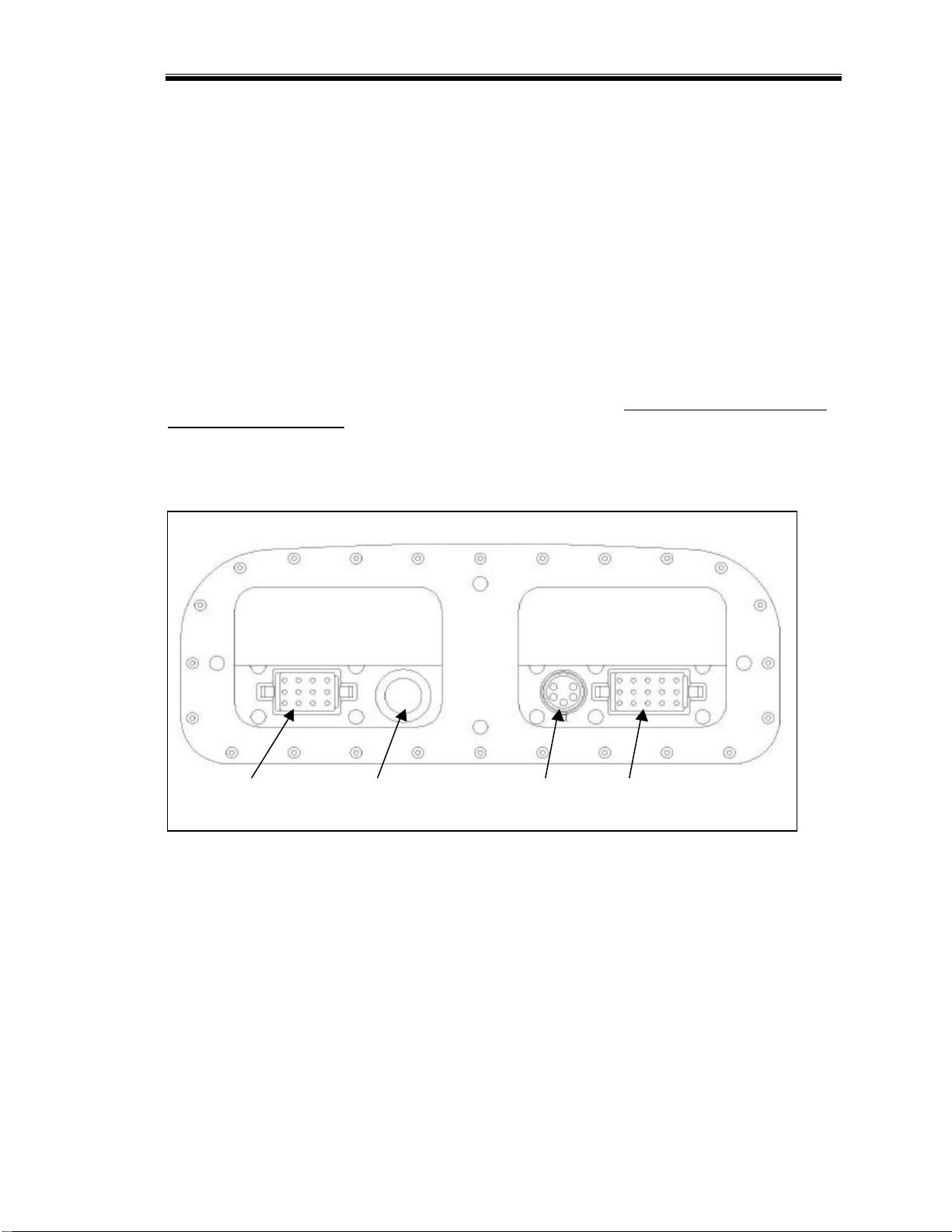
Port Descriptions...........................................................................................................3
Port A Wiring...................................................................................................................4
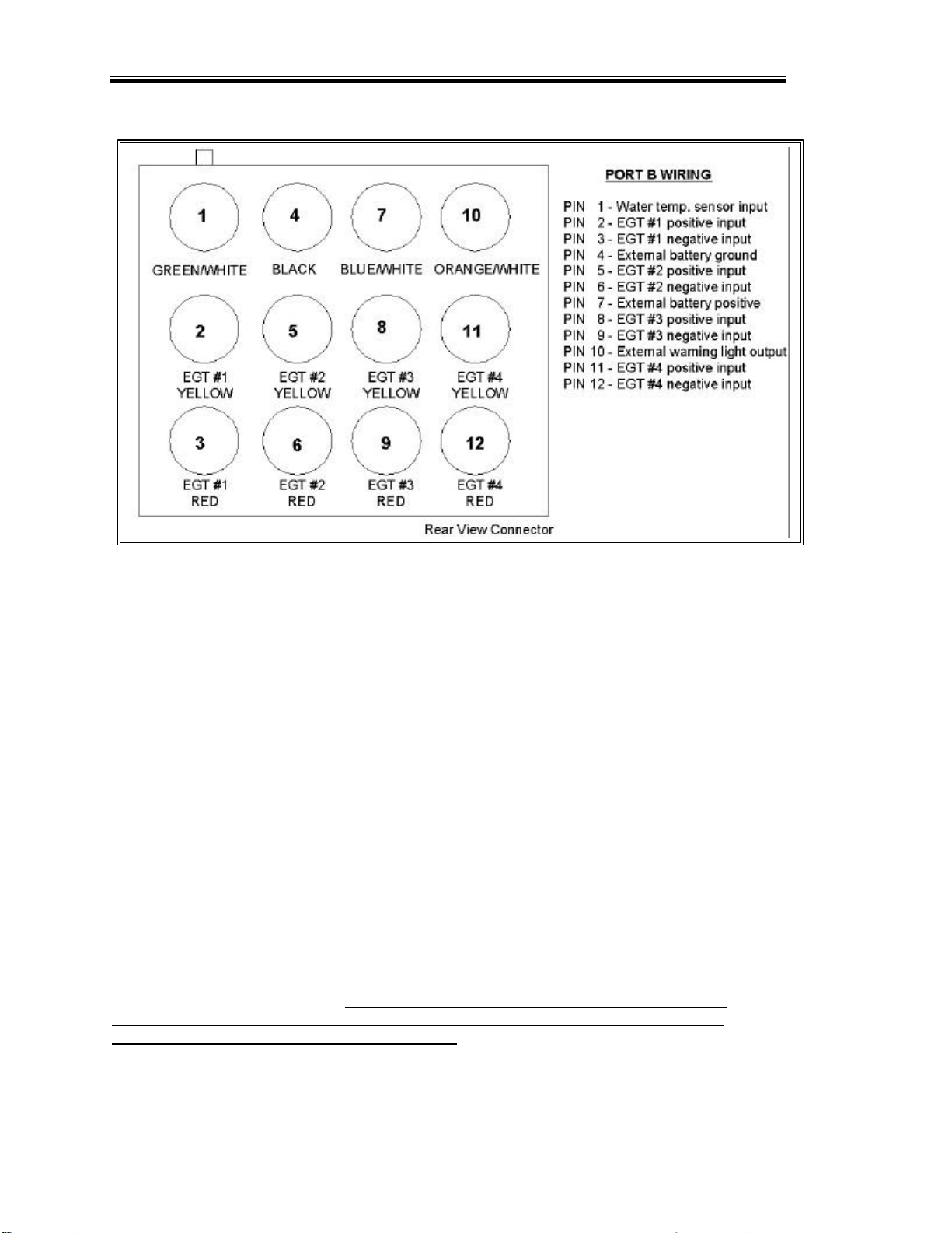
Port B Wiring...................................................................................................................6
Sensor Installation.........................................................................................................7
EGT Probe Installation.................................................................................................7
Water Temperature Sensor Installation.....................................................................7
Removing Wires from the Connector and/or changing EGT Probes....................7
Jack Shaft Sensor and Collar Installation.................................................................7
Remote Switch..............................................................................................................8
External Battery.............................................................................................................8
Installing V-Net Channels ............................................................................................9
Programming and Operation Using the Dash Buttons......................................11
How the Buttons Work:..............................................................................................11
Display Modes.............................................................................................................12
Setup Mode..............................................................................................................12
Speedometer Calibration....................................................................................15
Fuel Level Calibration..........................................................................................15
Real-time Mode........................................................................................................16
Scroll Mode...............................................................................................................17
Min –Max Recall Mode..........................................................................................19
Record Mode...........................................................................................................19
Playback Mode.........................................................................................................19
Warning Indicators......................................................................................................20
Clearing Alpha Display Warnings .........................................................................21
Programming Using the DataLink PC software...................................................23
Installing the DataLink Software...............................................................................23

Table of Contents
DataLink Software CD Installation........................................................................23
Installing the License Disk......................................................................................23
Connecting the Data Logger Serial Communications Cable ...............................23
Modifying the Dash Configuration............................................................................24
Changing Display Page Properities......................Error! Bookmark not defined.
Adding or Removing V-Net Devices to your System.............................................28
Configuring Record Parameters..............................................................................29
Setting the Record Length.....................................................................................30
Setting the Record Enable Channel.....................................................................30
Setting the Record Start Threshold ......................................................................30
Sending the Record Parameters...........................................................................31
Transferring Data to a PC..........................................................................................33
Using the Serial Communications Port to Transfer Data to your PC..................33
Naming and Storing the Run Data File ................................................................33
Viewing Real Time Data on a PC..............................................................................35
Setting up the Real Time Telemetry Parameters...................................................35
Entering the DataLink Telemetry Parameters.....................................................35
Starting a Telemetry Session................................................................................36

Introduction
1
Introduction
This manual contains the information required to install and program your Ultra Dash. If you have
purchased the PC download kit, you should have received a DataLink manual as well. Refer to the
DataLink manual for information on using the DataLink software to view the data from your dash.
Six Button Dash Features
•Engine and jack shaft RPM.
•Speedometer
•Four exhaustgas temperature inputs. (sensors sold separately)
•One water temperature.
•Ace M10 setting input.
•Warning indicator inputs for the following items:
oLow oil
oWater temperature
oHigh beam
oDetonation
oPremium fuel
•External warning indicator output.
•Internal warning indicator light.
•Internal high beam indicator light.
•V-Net port for expansion of up to 5 additional channels.
•Ten minutes of record and playback memory.
•Minimum and Maximum recall.
•Electro luminescent(EL) back light.
Package Contents
The Ultra Dash kit should contain the following components:
1 –6 Button Ultra Dash Display
1 –12 position connector and wires
1 –15 position connector and wires
1 –Water temperature sensor
1 –Jack shaft RPM sensor (jack shaft collar and magnet sold separately)
1 –Remote switch
1 –Wire terminal kit
1 –Instruction manual
1 –Cut out template
If you are missing any of the above components please contact your dealer immediately.
Optional Items:
oJack shaft collar. Required for speedometer. Available sizes: 0.75”, 1.00”, 1.125”, 1.25”
oData transfer to DataLink PC analysis software.

Introduction
2

Ultra Dash Installation
3
Ultra Dash Installation
Selecting a Mounting Location
Select a mounting location that does not expose the Ultra Dash to high temperatures. Avoid exposing the
front LCD to direct sunlight. Extreme overheating from the sun can temporarily cause the LCD to turn
entirely black. Although the dash is water resistant (i.e. rain, snow), you should never submerge any part of
the dash under water.
Dash Mounting
Once you have decided on a mounting location use the supplied template to cut out the rear dash inserts and
drill holes for the mounting studs.
Use the supplied machine nuts and locking washers to bolts in the dash. Do not use thread lock or nylock
nuts on the mountingstuds.
Port Descriptions
Connector Locations
Port B Serial Port V-Net Port Port A
Port A --- Port A is used to connect the main power source, warning indicator inputs, Ace setting input,
engine RPM and jack shaftrpm inputs. See the sectionPort A Wiring for complete instructions.
Port B --- Port B is used to connect the 4 EGT probes, water temperature sensor, external warning output
and external battery. The EGT probes are sold separately and are not factory installed in the connector.
You must install the probes in to the appropriate connector position yourself. See the sectionPort B
Wiring for complete instructions.
Serial Port --- The serial port is used to program the dash and download data using the DataLink PC
software.
V-Net Port --- The V-Net can be used to install up to 5 additional analog or digital inputs.

Ultra Dash Installation
4
Port A Wiring
Port A uses the 15 position connector. The only factory installed wires in the port A connector are the ones
required for power and ground. All other wires are provided with the pins crimped and ready to install if
needed. A description of each wire and its function is described below. If you decide not to use an input
you may leave the wire uninstalled.
Pin 1 –Fuel Level Sensor Input –0-5 volt input. Not used in most applications. Can be connected to any
standard fuel level sensor.
Pin 2 –Ace M10 Suspension Control Input –When the orange wire is connected the Ace setting will be
displayed in the upper left hand corner of the dash. Insert the orange wire in pin position 2. Connect the
other end of the orange wire to the Ace M10 controller gauge output wire.
Pin 3 –Not Used.
Pin 4 –Premium Fuel Indicator Input –Grounding the brown wire will cause the premium fuel indicator
to activate. Insert the brown wire in pin position 4. Connect the other end of the brown wire to the factory
installed premium fuel indicator wire.
Pin 5 –Detonation Indicator Input –Grounding the pink wire will cause the Detonation indicator to
activate. Insert the pink wire in pin position 5. Connect the other end of the pink wire to the factory
installed detonation indicator wire.
Pin 6 –High Beam Indicator Input –Applying power to the green wire will cause the high beam
indicator light in the upper right corner of the dash to activate. Insert the green wire in pin position 6.
Connect the other end of the green wire to the high beam wire.
Pin 7 –High Water Temperature Indicator Input –Grounding the gray wire will cause the high water
temperature indicator to activate. Insert the gray wire in pin position 7. Connect the other end of the gray

Ultra Dash Installation
5
wire to the factory installed water temperature switch wire. Do not confuse a water temperature switch
with a water temperature sensor. If you are using a water temperature sensor do not use this input. See
Port B Wiring pin 1 for instructions.
Pin 8 –Low Oil Indicator Input –Applying power to the tan wire will cause the low oil indicator to
activate. Insert the tanwire in pin position 8. Connect the other end of the tan wire to the factory installed
low oil switch. If your oil level switch goes to ground when activated you will need to install the ground
logic level converter contained in the port A wire harness kit. Follow the installation instructions provided
in the package.
Pin 9 –Remote Switch Input –When the blue wire is grounded the remote switch input will activate.
Insert the blue wire in pin position 9. Trim the other end of the blue wire to the desired length and connect
it to the blue wire on the remote switch using the connectors provided in the remote switch package.
Pin 10 –Not Used.
Pin 11 –Remote Switch Ground –Insert the black wire from the remote switch in pin position 11.
Alternately,you can connect the black wire from the remote switch to a good chassis ground instead of
running the wire back to pin 11 on the dash.
Pin 12 –Jack shaft RPM and Speedometer –Insert the purple wire in pin position 12. Connect the other
end of purple wire to the red connector on the jack shaft sensor. See the sectionJack Shaft Sensor and
Collar Installation for complete instructions on installing the jack shaft sensor.
Pin 13 –AC/DC power and Engine RPM input –When AC or DC power is applied to this wire the dash
will automatically turn on. Connect the red wire to the engine lighting coil. Using this method will get
power and the engine RPM signal from this single wire. If only DC power is available then connect the red
wire to a DC power source. Using a DC power source will require connecting the yellow wire on pin 15 to
get an engine RPM signal. See below for details.
Pin 14 –Ground –Connect the black wire to a solid chassis ground.
Pin 15 –Alternate Engine RPM input –If the red wire is connected to a DC power source you must
connect the yellow wire to a valid square wave tachometer output signal in order to get a proper engine
RPM reading. Do not connect this wire if the red wire is connected to the AC voltage output from the
engine lighting coil.

Ultra Dash Installation
6
Port B Wiring
Port B uses the 12 position connector. Since all port B inputs are optional the wires are provided with the
connector pins crimped but the wires are not installed in the connector. A description of each wire and its
function is described below. If you decide not to use an input you may leave the wire uninstalled.
Pin 1 –Water Temperature Sensors–Insert the green/white wire in pin position 1. Connect the
green/white wire to the optional water temperature sensor. This sensor is used to read the actual
temperature in degrees F or C. Do not confuse this input with a high water temperature alarm switch input.
If you would like to use the factory installed temperature alarm switch do not use this wire. See Port A
Wiring pin 7 for instructions.
Pin 2 –EGT #1 Probe Positive –Insert the yellow wire from EGT #1 probe in pin position 2.
Pin 3 –EGT #1 Probe Negative –Insert the red wire from EGT #1 probe in pin position 3.
Pin 4 –External Battery Ground–Connect this wire only if you plan to use an external DC battery to
power the dash when the engine is not running. Insert the black wire in pin position 3. Connect the black
wire to the ground wire on the external battery.
Pin 5 –EGT #2 Probe Positive –Insert the yellow wire from EGT #2 probe in pin position 5.
Pin 6 –EGT #2 Probe Negative –Insert the red wire from EGT #2 probe in pin position 6.
Pin 7 –External Battery Positive –Connect this wire only if you plan to use an external DC voltage Ni-
Cad battery to power the dash when the engine is not running. Insert the blue/white wire in pin position 7.
Connect blue/white wire to the positive wire on the external battery. Note: A minimum of 9 volts is
required to properly power the dash. DO NOT CONNECT THIS WIRE TO THE ENGINE LIGHTING
COIL OR ANY OTHER AC VOLTAGE SOURCE. DOING SO WILL CAUSE SEVERE DAMAGE TO
YOUR DASH AND WILL VOID YOUR WARRANTY!!!
Pin 8 –EGT #3 Probe Positive –Insert the yellow wire from EGT #3 probe inpin position 8.
Pin 9 –EGT #3 Probe Negative –Insert the red wire from EGT #3 probe in pin position 9.

Ultra Dash Installation
7
Pin 10 –External Warning Light Output –Connect this wire only if you plan to use an external warning
light. Insert the orange/white wire in pin position 10. Connect the other end of the orange/white wire to
the ground side of your warning light. Connect the other side of the warning light to power.
Pin 11 –EGT #4 Probe Positive –Insert the yellow wire from EGT #4 probe in pin position 11.
Pin 12 –EGT #4 Probe Negative –Insert the red wire from EGT #4 probe in pin position 12.
Sensor Installation
EGT Probe Installation
Instructions for the installing the EGT probes in the pipe are provided in the EGT probe package. Follow
the instructions provided in the package.
Water Temperature Sensor Installation
The water temperature sensor is typically installed in place of the OEM temperature switch. The water
temperature sensor provided uses 1/8” NPT thread. An adaptor will be required if your current temperature
switch uses a larger thread. Make sure to use thread sealer when installing the sensor to prevent water
leaks.
Removing Wires from the Connector and/or changing EGT Probes
Removing a wire from the connector or changing an EGT probe requires a special tool which can be
purchased from your dealer. Carefully follow the instructions provided with the tool if you need to remove
a pin from the connector.
Jack Shaft Sensor and Collar Installation
Due to the various jack shaft diameters the collar which holds the magnet must be purchased separately. If
you did not purchase a jack shaft collar contact your dealer for more information.
Install the collar on the jack shaft. Make sure the collar fits snug and cannot slip. If the collar does not fit
properly contact your dealer to obtain a correctly sized collar. Mount the sensor so that it is directly over
the collar and has 0.050” to 0.075” air gap. Connect the purple wire from the dash port A pin 12 to the red
connector on the sensor. Connect the sensors black wire to chassis ground.
Jack Shaft Collar

Ultra Dash Installation
8
Remote Switch
The remote switch is used to change dash displays and start recording data without the rider having to
remove their hand from the bars. The remote switch also used to record data for playback. If you do not
wish to use these functions you may leave the remote switch uninstalled if desired.
ACTION FUNCTION
Press and release button Scroll between the three display pages
Press and hold button until the word REC
appears below the swept tach. Dash will begin recording. (See Recoding Mode)
External Battery
An external Ni-Cad battery can be used to power the dash when the engine is not running and power is not
available to the main power input at port A pin 13. When the engine is shut off or the main power is
disconnected the dash will remain powered on the external battery until the max. on time has expired
without any button presses. (see Setup mode MXON). To turn the dash on without main power, press and
hold the button until the dash completely turns on. See Port B Wiring for information on wiring an
external battery.
WARNING!!
While the engine is running the dash will slowly charge the external battery. Make sure to only
use a 9–18 volt Ni-Cad battery. Attempting to use and charge other types of batteries could
cause them to leak and/or explode.

Ultra Dash Installation
9
Installing V-Net Channels
You can add up to five additional channels to your Ultra Dash by installing modules on the V-Net port. For
instance, if you wanted to monitor turbo boost pressure you would need to purchase a boost pressure V-Net
module. Follow the steps below to add V-Net modules to your Ultra Dash.
Step #1 —Unplug the factory installed terminator cap from the V-Net port on the back of the dash
Step #2 —Plug the V-Net extension cable in the V-Net port.
Step #3 —Plug the other end of the V-Net cable in to the first V-Net module. You can install up to five V-
Net modules. You can plug the V-Net modules in any order that is convenient. The modules can be
plugged directly in to each other or a V-Net extension cable can be used between modules if necessary.
Step #4 —Plug the terminator cap removed in step #1 in to the last V-Net module.
Module
& Sensor
Terminator
Cap
Ultra Dash
V-Net Port
Module
& Sensor
IMPORTANT!!
Do not use two modules with the same V-Net ID.
The V-Net ID can be found on the front page of
the documentation included with each V-Net
module.


Programming and Operation Using the Dash Buttons
11
DISP
MODE ODO
!
Programming and Operation Using the Dash Buttons
After installation the first thing you should do is configure the setup parameters. Although the factory
defaults will work fine for most users, you should run through the configuration setup and adjust the engine
rpm pulses per revolution, EGT warning levels and speedometer calibration. There are two methods that
can be used to configure the dash. The first method uses the buttons on the front of the dash. Using this
method you can program the basic features requiredfor most users. However, if you would like to add a
fourth display set or reconfigure any of the factory default display sets you must use the second method,
which is the DataLink PC software. Instructions for using both methods is describe below in this chapter.
How the Buttons Work:
Each button can perform three different functions depending on how long the button is held down. In this
manual we will refer to the three different button press types as SHORT, MED and LONG. To help
determine when to release the button, and as a result the type of button press, you need to look at the
warning indicators in the upper corners of the dash. If you release the button after one flash a SHORT
button press will be entered. Releasing the button after two flashes will result in a MED button press and
three flashes will result in a LONG button press. Table 1 list the three different button press types.
Type Warning Flashes Time in Seconds
SHORT 1Less than 2
MED 22
LONG 33 or more
Table 1
WarningSwept Tach Middle Center High Beam
Upper Left
Lower Left Lower Center Lower Right
Figure 1
Figure 1 illustrates the channel positions and labels the terminology used in this manual to describe each
position on the LCD display. There are six channel positions on the LCD and two indicator lights in each
upper corner. The lower left channel position can display both numbers and letters. The other five
positions can only display numerical values.

Programming and Operation Using the Dash Buttons
12
Display Modes
The behavior of each button press depends on the mode the dash is currently in. See the appropriate mode
section below for a list of button behaviors in each mode.
There are 6 different modes.
•Setup Mode
•Real-time Mode
•Scroll Mode
•Min –Max Recall Mode
•Recording Mode
•Playback Mode
Setup Mode
Turn the dash on by either starting the engine or, if you have an external battery connected, pressing and
holding the button until the display turns on. Enter a MED press on the button by pressing and
holding for two warning light flashes. While in setup mode a SHORT press on the button will
change to the next setup parameter. A MED press on the button will step back to the previous setup
parameter. A SHORT press on the and buttons will increase or decrease the parameter value in
small increments. A LONG press on the and buttons will increase or decrease the parameter
value in large increments. To exit setup mode enter a LONG press on the button until the word
WAIT is displayed in the lower left LCD position. Make sure you do not turn the dash off until the word
WAIT has disappeared and the dash has reset.
Table 2 shows the behavior of each button while in Setup mode.
Button SHORT Button Press
(one light flash) MED Button Press
(two light flashes) LONG Button Press
(three light flashes)
Does nothing Does nothing Exit Setup mode
Does nothing Does nothing Does nothing
Change to next setup
parameter Change to previous
setup parameter Does nothing
Does nothing Does nothing Does nothing
Increase parameter value
in small step
Increase parameter
value in large step
(where appropriate)
Increase parameter
quickly
Decrease parameter value
in small step
Decrease parameter
value in large step
(where appropriate)
Decrease parameter
quickly
Table 2

Programming and Operation Using the Dash Buttons
13
Table 3 shows each setup parameter and the available options.
#Parameter Description Lower
Left LCD
Code Available Options (Lower Right LCD) Factory
Default
1Default back light intensity
level bLIT Level 0-9
9 = highest level 6 = factory default 6
2Default Display Page
(see Real-time section for
info) dISP 1, 2, 3 1
3Units of Measure UNIT 0=English
1=Metric 0
4Engine RPM odd fire OddF 0 –8
Set to 0 if your engine is not an odd fire 0
5Engine RPM pulses per
revolution R1 P 0 –20
6 is correct for most snowmobiles.
6
6Swept tach engine rpm
scale SCAL 0 = 11,500 rpm max
1 = 13,500 rpm max 0
7Engine RPM rev warning REVL 0 –20,000 RPM 8,500
8Jack shaft sensor type R2TY 0 = Magnet switch
1 = Zero crossing 0
9Number of magnets in jack
shaft collar (pulses per rev)
R2 P 0 –20
1 is standard setting 1
10
Jack shaft pulses in 1/8th
mile/km (seeSpeedometer
Calibration section) P8MI 0 –10,000 660
11
Jack shaft pulses in 1
mile/km (see Speedometer
Calibration section) P1MI 0 –10,000 5280
12
Odometer Starting Value OdOS 0 –320,000 0
13
Water temp. sensor type WTYP 0 –6
4 = standard sensor provided with kit
4
14
Fuel tank empty value.
(see Fuel Level
Calibration section) FTLO 0 –5,000 0
15
Fuel tank full value.
(see Fuel Level
Calibration section) FTHI 0 –5,000 5000

Programming and Operation Using the Dash Buttons
14
16
Remote switch input value
when ON. SWON 0 = input is grounded when ON
1 = input has voltage when ON 0
17
High beam indicator input
value when ON. HbON 0 = input is grounded when ON
1 = input has voltage when ON 1
18
Detonation indicator input
value when ON. SWON 0 = input is grounded when ON
1 = input has voltage when ON 0
19
Premium fuel indicator
input value when ON. PFON 0 = input is grounded when ON
1 = input has voltage when ON 0
20
Low oil level indicator input
value when ON. OLON 0 = input is grounded when ON
1 = input has voltage when ON 1
21
High water temp. switch
indicator input value when
ON. HWON 0 = input is grounded when ON
1 = input has voltage when ON 0
22
EGT #1 alarm level EGT1 0 –1700 Deg. 1350
23
EGT #2 alarm level EGT2 0 –1700 Deg. 1350
24
EGT #3 alarm level EGT3 0 –1700 Deg. 1350
25
EGT #4 alarm level EGT4 0 –1700 Deg. 1350
26
High water temp alarm
level H2OT 0 –300 Deg. 170
27
Auto off time. MXON 0 –100 minutes 5
Table 3

Programming and Operation Using the Dash Buttons
15
Speedometer Calibration
The speedometer, odometer and trip odometer will not read correctly you perform the following calibration
procedure.
1) Turn on the dash and enter setup mode by entering a MED press on the button.
2) Step through each setup parameter by entering a SHORT press on the button until you reach
the P8MI parameter in the lower left LCD position.
3) Drive exactly 1/8 of mile (660 ft) and stop.
4) Enter a SHORT press on the button to set the calibration factor.
5) Exit setup mode by entering a LONG press on the button until the word WAIT is displayed
in the lower left LCD position. Make sure you do not turn the dash off until the wordWAIT has
disappeared and the dash has reset.
Fuel Level Calibration
From the factory, the fuel level will read from 0 to 5000. If you would like the fuel level to read from 0 to
100 percent you must properly perform the following calibration procedure.
1) Empty the fuel tank to the level you wish to call %0.
2) Turn on the dash and enter setup mode by entering a MED press on the button.
3) Step through each setup parameter by entering a SHORT press on the button until you reach
the FTLO parameter in the lower left LCD position.
4) Enter a SHORT press on the button to set the tanks empty value.
5) Enter a SHORT press on the button to reach the next parameter FTHI.
6) Fill the fuel tank to the level you wish to call %100.
7) Enter a SHORT press on the button to set the tanks full value.
8) Exit setup mode by entering a LONG press on the button until the wordWAIT is displayed
in the lower left LCD position. Make sure you do not turn the dash off until the wordWAIT has
disappeared and the dash has reset.

Programming and Operation Using the Dash Buttons
16
Real-time Mode
The dash will power up in Real-time mode each time it is turned on. While in Real-time mode you can
scroll between the three main display pages by entering a SHORT key press on the button. To change
the lower right display enter a SHORT press on the button.
Table 4 shows the channel positions for each of the three display pages. These are the factory defaults.
They can be changed using the DataLink PC software.
LCD Section Channel Displayed
Swept Tach Engine RPM
Middle Center Speedometer
Upper Left Fuel Level
Lower Left Water Temperature
Lower CenterMaximum Exhaust Gas Temperature Value and Cylinder Number
DISPLAY #1
Lower Right Odometer/ Trip / EGT 3 / EGT 4 (see note below)
Swept Tach Speedometer
Middle Center Engine RPM
Upper Left Ace Setting
Lower Left Water Temperature
Lower Center Maximum EGT Value and Cylinder Number
DISPLAY #2
Lower Right Odometer/ Trip / EGT 3 / EGT 4 (see note below)
Swept Tach Engine RPM
Middle Center Speedometer
Upper Left Water Temperature
Lower Left EGT 1
Lower Center EGT 2
DISPLAY #3
Lower Right Odometer/ Trip / EGT 3 / EGT 4 (see note below)
Table 4
Note: The number 4 will not show in the channel tag when EGT four is displayed in the lower right corner.
Only the tag EGT will display for channel four.
Table of contents
Other Racepak Automobile Accessories manuals