RACOM RipEX2-HS User manual

User manual
.
RipEX2-HS
.
version 1.2
2019-11-26
fw 1.3.2.0
www.racom.eu
RACOM s.r.o. | Mirova 1283 | 592 31 Nove Mesto na Morave | Czech Republic
Tel.: +420 722 937 522 | E -mail: [email protected]


Table of Contents
Important Notice .................................................................................................................................. 5
Getting started ..................................................................................................................................... 6
1. RipEX2 Hot Standby ....................................................................................................................... 7
1.1. Introduction ........................................................................................................................... 7
2. RipEX2-HS in detail ......................................................................................................................... 8
2.1. Functionality ......................................................................................................................... 8
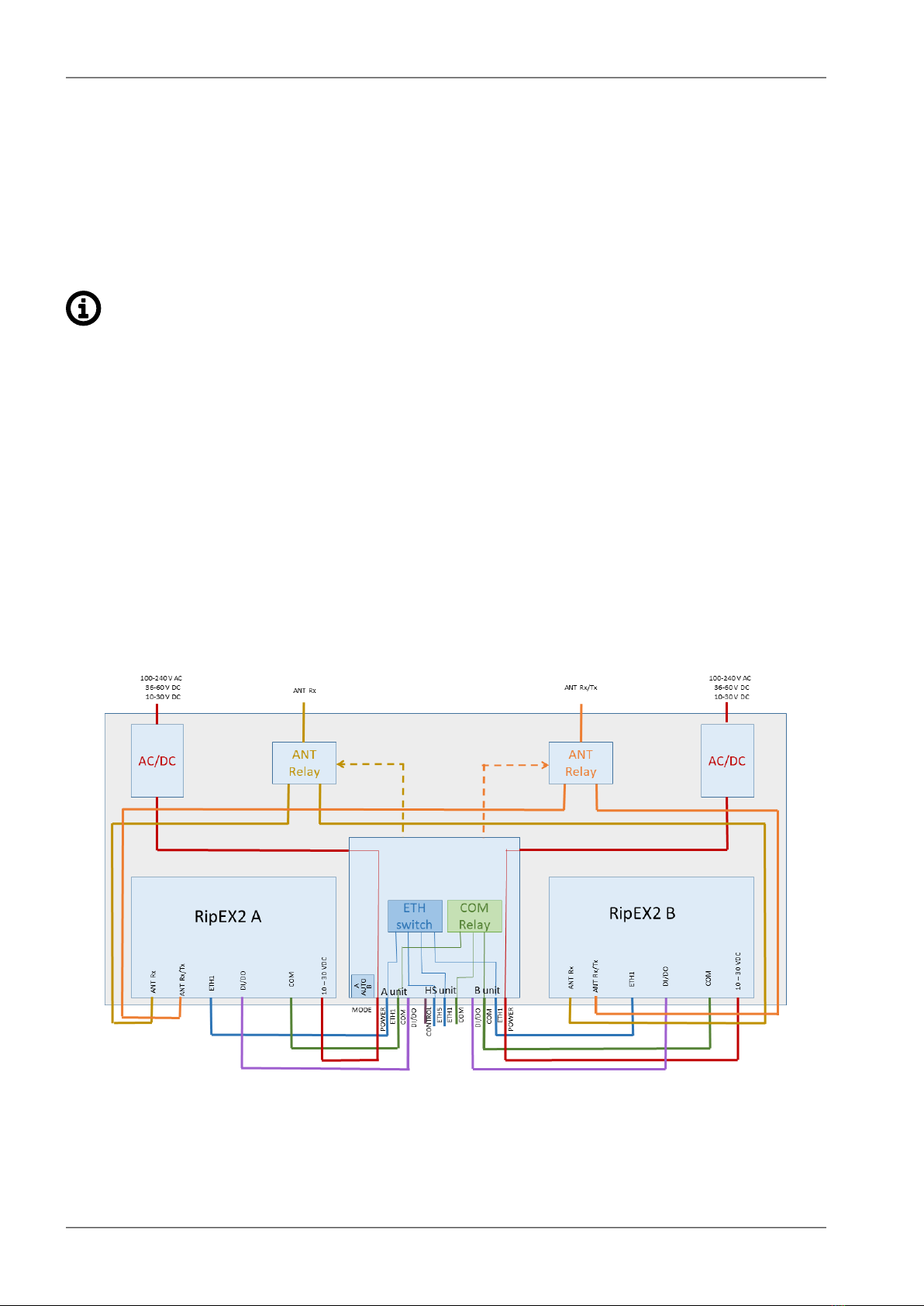
2.2. Block diagram ....................................................................................................................... 8
2.3. Operating modes .................................................................................................................. 9
2.4. Switching over ...................................................................................................................... 9
2.5. HW alarms ............................................................................................................................ 9
3. Product .......................................................................................................................................... 10
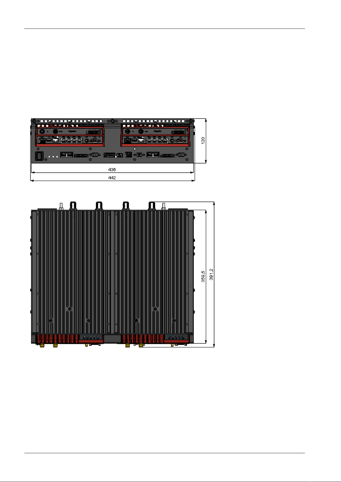
3.1. Dimensions ......................................................................................................................... 10
3.2. Front panel RipEX2-HS ..................................................................................................... 13
3.3. Rear panel .......................................................................................................................... 16
4. Installation ..................................................................................................................................... 19
4.1. Mounting ............................................................................................................................. 19
4.2. Power ................................................................................................................................. 21
4.3. Grounding ........................................................................................................................... 22
4.4. Antenna .............................................................................................................................. 22
5. Settings ......................................................................................................................................... 23
6. Troubleshooting ............................................................................................................................. 25
7. Technical parameters .................................................................................................................... 26
8. Safety, environment, licensing ....................................................................................................... 28
8.1. Frequency .......................................................................................................................... 28
8.2. Safety distance ................................................................................................................... 28
8.3. Electric power shock hazard .............................................................................................. 28
8.4. High temperature ................................................................................................................ 28
8.5. RoHS and WEEE compliance ............................................................................................ 29
8.6. Conditions of Liability for Defects and Instructions for Safe Operation of Equipment ........ 31
8.7. Important Notifications ........................................................................................................ 32
8.8. Product Conformity ............................................................................................................. 33
8.9. Warranty ............................................................................................................................. 34
A. Abbreviations ................................................................................................................................ 35
Revision History ................................................................................................................................ 36
List of Figures
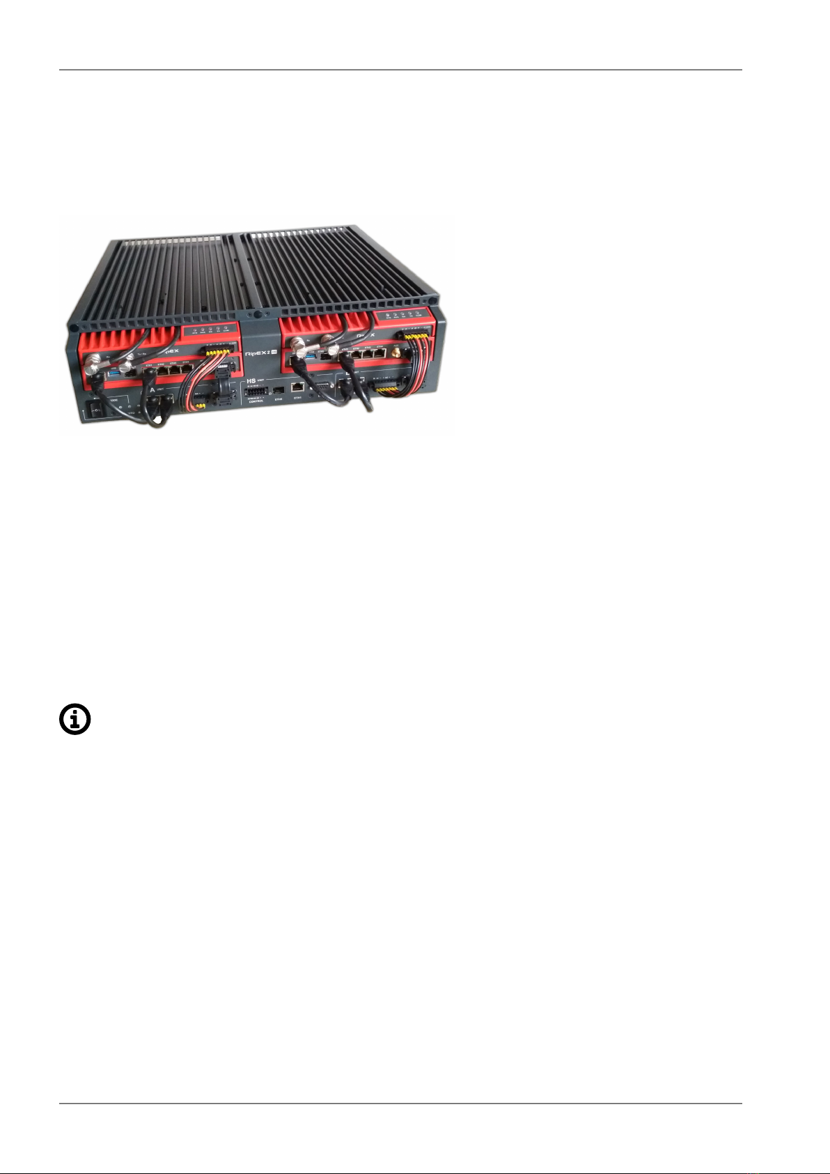
1. RipEX2-HS ...................................................................................................................................... 6
2.1. Block diagram ............................................................................................................................... 8
3.1. RipEX2-HS dimensions .............................................................................................................. 10
3.2. RipEX2-RD dimensions .............................................................................................................. 11
3.3. RipEX2-RS dimensions .............................................................................................................. 12
3.4. RipEX2-HS front panel ............................................................................................................... 13
3.5. HS unit ........................................................................................................................................ 13
3.6. A unit, B unit ............................................................................................................................... 14
3.7. LED panel ................................................................................................................................... 15
3.8. RipEX2-HS/RD/RS rear panel ................................................................................................... 16
3.9. N connector ................................................................................................................................ 17
3.10. Power supply connector AC model .......................................................................................... 18
3.11. Power supply connector DC model .......................................................................................... 18
3© RACOM s.r.o. – RipEX2-HS

4.1. RipEX2-HS Rack mounted ......................................................................................................... 19
4.2. RipEX2-HS/RD/RS rack tray shelf ............................................................................................. 19
4.3. RipEX2-HS/RD/RS L profile mount ............................................................................................ 20
4.4. RipEX2-HS/RD/RS rack mount kit ............................................................................................. 21
4.5. RipEX2-HS grounding in a cabinet ............................................................................................ 22
8.1. EU Declaration of Conformity RoHS, WEEE ............................................................................. 30
8.2. EU Declaration of Conformity RED ............................................................................................ 33
RipEX2-HS – © RACOM s.r.o.4
RipEX2-HS

Important Notice
Copyright
© 2019 RACOM. All rights reserved.
Products offered may contain software proprietary to RACOM s. r. o. (further referred to under the ab-
breviated name RACOM). The offer of supply of these products and services does not include or infer
any transfer of ownership. No part of the documentation or information supplied may be divulged to
any third party without the express written consent of RACOM.
Disclaimer
Although every precaution has been taken in preparing this information, RACOM assumes no liability
for errors and omissions, or any damages resulting from the use of this information. This document or
the equipment may be modified without notice, in the interests of improving the product.
Trademark
All trademarks and product names are the property of their respective owners.
Important Notice
• Due to the nature of wireless communications, transmission and reception of data can never be
guaranteed. Data may be delayed, corrupted (i.e., have errors), or be totally lost. Significant delays
or losses of data are rare when wireless devices such as the RipEX2-HS are used in an appropriate
manner within a well‐constructed network. RipEX2-HS should not be used in situations where failure
to transmit or receive data could result in damage of any kind to the user or any other party, including
but not limited to personal injury, death, or loss of property. RACOM accepts no liability for damages
of any kind resulting from delays or errors in data transmitted or received using RipEX2-HS, or for
the failure of RipEX2-HS to transmit or receive such data.
• Under no circumstances is RACOM or any other company or person responsible for incidental, acci-
dental or related damage arising as a result of the use of this product. RACOM does not provide the
user with any form of guarantee containing assurance of the suitability and applicability for its applic-
ation.
• RACOM products are not developed, designed or tested for use in applications which may directly
affect health and/or life functions of humans or animals, nor to be a component of similarly important
systems, and RACOM does not provide any guarantee when company products are used in such
applications.
5© RACOM s.r.o. – RipEX2-HS
Important Notice

Getting started
RipEX2-HS serves as a redundant station equipped with two standard RipEX2 radio modems using a
hot standby functionality. All you have to do to put it into operation is to connect properly all connectors
and configure internal RipEX2 units using a PC and a web browser.
Fig. 1: RipEX2-HS
RipEX2 access defaults: IP 192.168.169.169/24, username: admin, password: admin or IP 10.9.8.7
when accessing over the optional USB/ETH adapter or Wifi adapter.
Power on the RipEX2-HS and wait approx. for 25 seconds for the RipEX2 OS to boot. When accessing
over the optional USB/ETH adapter or Wifi adapter, your PC will get its IP settings from the built-in
DHCP server and you have to type https://10.9.8.7 in your browser.
When accessing over Ethernet, set a static IP 192.168.169.x/24 on your PC first, connect your PC to
RipEX2 ETH interface, start your browser and type https://192.168.169.169 in the address line. When
accessing RipEX2 for the first time and using https, you have to accept the https security certificate
issued by RACOM.
Note
Both RipEX2 units are in factory default settings.
RipEX2-HS – © RACOM s.r.o.6
Getting started

1. RipEX2 Hot Standby
1.1. Introduction
RipEX2-HS is designed to be used on critical sites, where high stress on HW reliability is required –
typically master or repeater stations. It is hot standby, 1+1 redundant, fully monitored, hot swappable
equipment.
RipEX2-HS is assembled with 2 standard RipEX2 units, each powered by its independent power supply.
Controller takes care of the automatic changeover in case of failure. Changeover conditions are widely
configurable. Since both units are hot standby and use identical MAC addresses addresses on ETH
interface, an, an exceptional switch-over time of less than 2 s is reached.
LED panel, Mode switch, HW alarm outputs, SNMP traps and standard RipEX2 units inside make
RipEX2-HS configuration and control quite easy and maintenance can be done by anyone familiar with
RipEX2.
7© RACOM s.r.o. – RipEX2-HS
RipEX2 Hot Standby

2. RipEX2-HS in detail
2.1. Functionality
There are two standard RipEX2 units with identical configurations inside RipEX2-HS. Both units are
booted, however only one is active. Some interfaces (COM, ETH1 and Radio) of the non-active unit
are disconnected.
Note
Even if Rx on inactive RipEX2 unit LED panel is blinking when the active unit is transmitting,
these packets are not received. I.e. they don’t take part in Statistic, Neighbours or Graphs.
When the active unit HW alarm output changes to “On” (e.g. when a controlled value exceeds the re-
spective threshold), the controller automatically switches interfaces (COM, ETH1, ANT–if applicable)
to the second unit and it takes over all functions. Since both units are using the same MAC addresses
(MAC cloning), there is a minimal drop-out while switching, less than 2 s.
When RipEX2 units inside RipEX2-HS are in Bridge mode, the first switch-over takes approx. 30 s. It
is because hot standby RipEX2 ARP table is clear and has to be filled with first packets (forward delay).
The next switch-over takes less than 2 s. When Operating mode is Router, even the first switch-over
takes less than 2 s. When ARP proxy in Router mode is used, switch-over time(s) is equal to that of
the Bridge mode.
2.2. Block diagram
Fig. 2.1: Block diagram
RipEX2-HS – © RACOM s.r.o.8
RipEX2-HS in detail

2.3. Operating modes
•Auto – primary active is RipEX2 “A”, when it fails, controller automatically switches-over to RipEX2
“B”. When both units are with alarms, “A” unit remains active.
•A– only RipEX2 “A” is active and controller will never switch to RipEX2 “B”
•B– only RipEX2 “B” is active and controller will never switch to RipEX2 “A”
Aand Bmodes are supposed to be used only for the maintenance/testing and not for normal service.
2.4. Switching over
In order to achieve maximum reliability, the controller is software free. Switching-over is based only on
HW alarm outputs of RipEX2 units and the HW signals from their power supplies.
The HW alarm of active RipEX2 or its power supply will cause the immediate and unconditional switch-
over to hot standby RipEX2. If there are any packets waiting in queues of RipEX2 which becomes in-
active, these packets are discarded after switch-over.
2.4.1. Power alarm
Power supply of respective unit is “Off” when the input voltage from the respective power supply to the
controller is out of voltage working range.
Some borderline examples for Auto mode (Primary unit is always “A”. The second unit is standby):
1. Power alarm of Primary unit is “On”
- Standby unit becomes active
2. Primary unit alarm is “On” and Power alarm of Standby is “On” or Standby unit alarm is “On”
- Nothing will be done. Primary unit remains active
3. Primary unit alarm is “On”, it was switched to Standby unit, Primary unit alarm disappeared
- it will be switched back to Primary unit immediately (the protective timeout of 30 s will be held for
shorter HW alarm output changes)
2.5. HW alarms
In order to achieve maximum reliability, the controller is software free. Switch-over is based only on
HW alarm outputs of RipEX2 units and their power supplies.
9© RACOM s.r.o. – RipEX2-HS
RipEX2-HS in detail

3. Product
3.1. Dimensions
3.1.1. RipEX2-HS
19" rack 3U, 442 W × 392 D × 120 H mm, 17.40 W × 15.43 D × 4.72 H inch.
Fig. 3.1: RipEX2-HS dimensions
RipEX2-HS – © RACOM s.r.o.10
Product

3.1.2. RipEX2-RD
19" rack 3U, 442 W × 392 D × 87 H mm, 17.40 W × 15.43 D × 3.42 H inch.
Fig. 3.2: RipEX2-RD dimensions
11© RACOM s.r.o. – RipEX2-HS
Product

3.1.3. RipEX2-RS
19" rack 3U, 442 W × 392 D × 87 H mm, 17.40 W × 15.43 D × 3.42 H inch.
Fig. 3.3: RipEX2-RS dimensions
RipEX2-HS – © RACOM s.r.o.12
Product

3.2. Front panel RipEX2-HS
Fig. 3.4: RipEX2-HS front panel
3.2.1. Connectors available on front panel
All connectors for RipEX2 units are described in RipEX2 User manual (Chap. 1.2)
Connectors of the RipEX2-HS are splitted to three sections HS unit, "A" unit and "B" unit.
Fig. 3.5: HS unit
Connectors of this sections serves as connection with external equipment.
Description of each connector is the same as with RipEX2 unit and you can find it in RipEX2 manual.
ETH1 and ETH5 (SFP) are connected to an internal switch, for connection of both ETH to the individual
RipEX2, units the ETH1 connector in A unit and B unit section shall be used.
12 pin connector (Type of plug Phoenix Contact 1790331)
Pin description
This input is connected to the SI pin on power connector of the active RipEX2
unit
SI Sleep input
This input is connected to the SI pin on power connector of the active RipEX2
unit
AI Alarm input
13© RACOM s.r.o. – RipEX2-HS
Product

Pin description
Allows HW driven switching between active units in AUTO modeH1
Allows HW driven switching between active units in AUTO modeH2
Alarm output of the "A" unit RipEX2AO
Alarm output of the "B" unit RipEX2BO
Alarm status output – indication of an alarm of HS controllerS1
Alarm status output – indication of an alarm of "A" unit or/and "B" unitS2
Fig. 3.6: A unit, B unit
Connectors of this section has to be interconnected with respective connectors of appropriate RipEX2
unit.
RipEX2-HS – © RACOM s.r.o.14
Product

3.2.2. LED panels description
Fig. 3.7: LED panel
Tab. 3.1: LED panel description
DescriptionSymbol
Dark mode AUTO is not active
AUTO1
Green solid – ready, both RipEX2 units
powered and no alarm known
red solid – alarm status, when only this
LED is red indicates alarm of the control-
ler, otherwise together with unit in alarm
status dark – RipEX2 "A" is not active
Green solid – Unit "A" active - selected as
active by switch
A
2
green blinking – AUTO mode ready to
serve
Red solid – unit in alarm status
Red blinking – power supply alarm (togeth-
er with red solid AUTO LED)
Green solid – active - selected as active
by switch
B3
Green blinking – AUTO mode ready to
serve
Red solid – unit in alarm status
Red blinking – power supply alarm (togeth-
er with red solid AUTO LED)
15© RACOM s.r.o. – RipEX2-HS
Product

Tab. 3.2: MODE selector
DescriptionMODE
RipEX2 unit "A" hard selected – it remains
active even in case of alarm on unit "A"
A
AUTO mode – A unit active till an alarm status
on "A" unit occurs, which causes switching to
unit "B".
AUTO
RipEX2 unit "B" hard selected – it remains
active even in case of alarm on unit "B"
B
For more details see Chapter 2, RipEX2-HS in detail.
Note
When testing the changeover, please wait at least 30 seconds between individual tests.
3.3. Rear panel
Fig. 3.8: RipEX2-HS/RD/RS rear panel
RipEX2-HS – © RACOM s.r.o.16
Product

3.3.2. A and B connectors
Fig. 3.10: Power supply connector AC model
Fig. 3.11: Power supply connector DC model
Power supply connector AC model
100–240 V AC equipped with T2.5A fuse
Optionally 36-60 V DC, 18-30 V DC or 10-30 V DC
RipEX2-HS – © RACOM s.r.o.18
Product

4. Installation
4.1. Mounting
There are 3 variants of Mounting RipEX2 units.
Fig. 4.1: RipEX2-HS Rack mounted
4.1.1. Mounting variant 1
Fig. 4.2: RipEX2-HS/RD/RS rack tray shelf
19© RACOM s.r.o. – RipEX2-HS
Installation

4.1.2. Mounting variant 2
Fig. 4.3: RipEX2-HS/RD/RS L profile mount
Note
Screw holes placement depends on depth of the Rack.
RipEX2-HS – © RACOM s.r.o.20
Installation
Other manuals for RipEX2-HS
1
Table of contents
Other RACOM Modem manuals
Popular Modem manuals by other brands

Planet Networking & Communication
Planet Networking & Communication ADE-2400 Quick installation guide

Trust
Trust 56K PC-CARD MODEM user manual

QuieTek
QuieTek I600 WiMAX manual

AOR
AOR ARD9000 instruction manual

Comtech EF Data
Comtech EF Data CIM-550 Installation and operation manual

Raveon Technologies Corporation
Raveon Technologies Corporation RV-PMTII Technical manual