rada Acu-T3 1.1664.001 User manual

11108900-W2-L
IMPORTANT
Installer: This Manual is the property of the
customer and must be retained with the product
for maintenance and operational purposes.
PRODUCT MANUAL
Rada Acu-T3 Digital Mixing Valve

2
1108900-W2-L
CONTENTS
Description...............................................................................................4
Patents and Design Registration..........................................................5
Safety : Warnings ....................................................................................5
Specications ..........................................................................................6
Installation ...............................................................................................7
General................................................................................................. 7
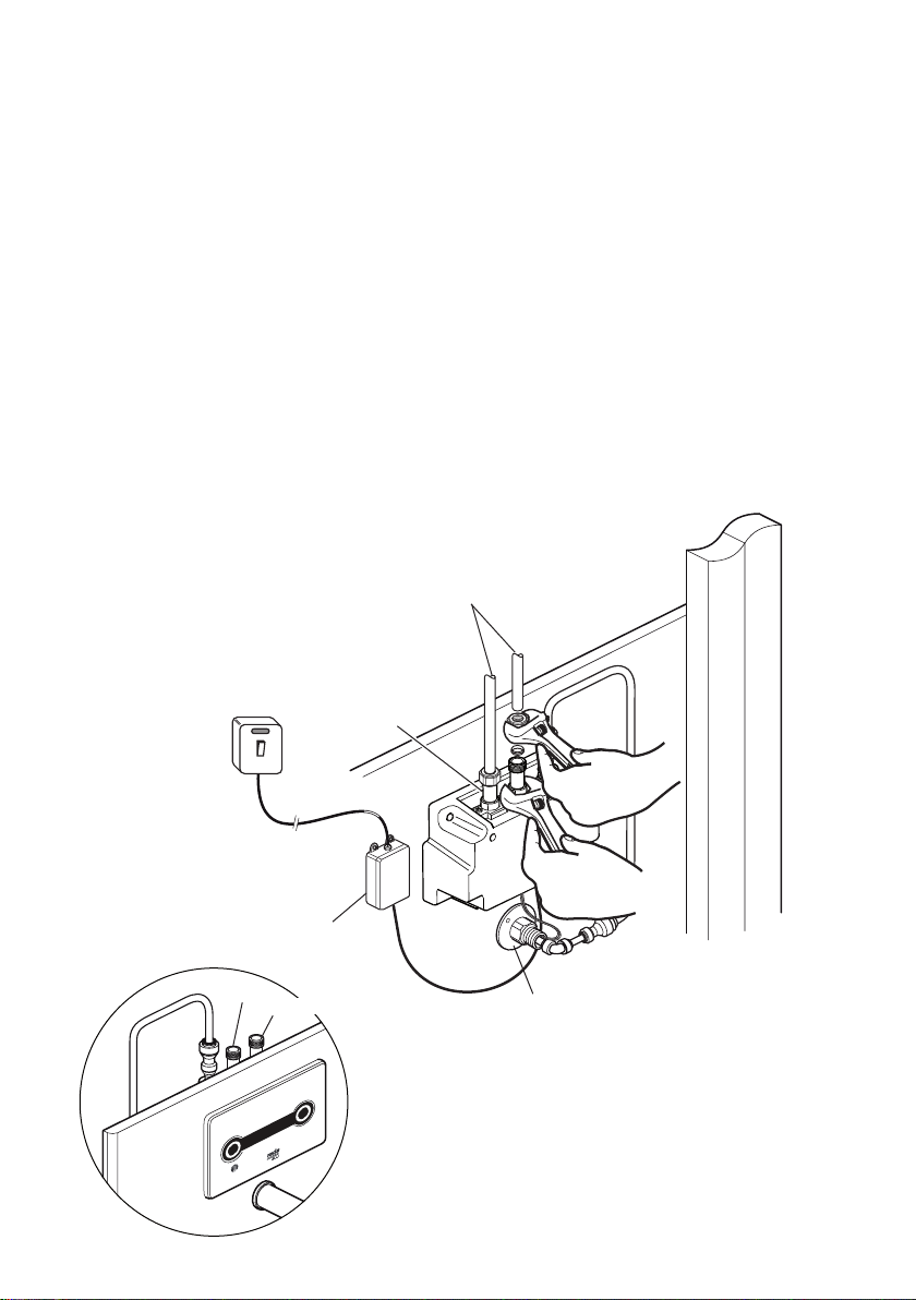
Make the connections to the Rada Acu................................................ 8
Commissioning .......................................................................................9
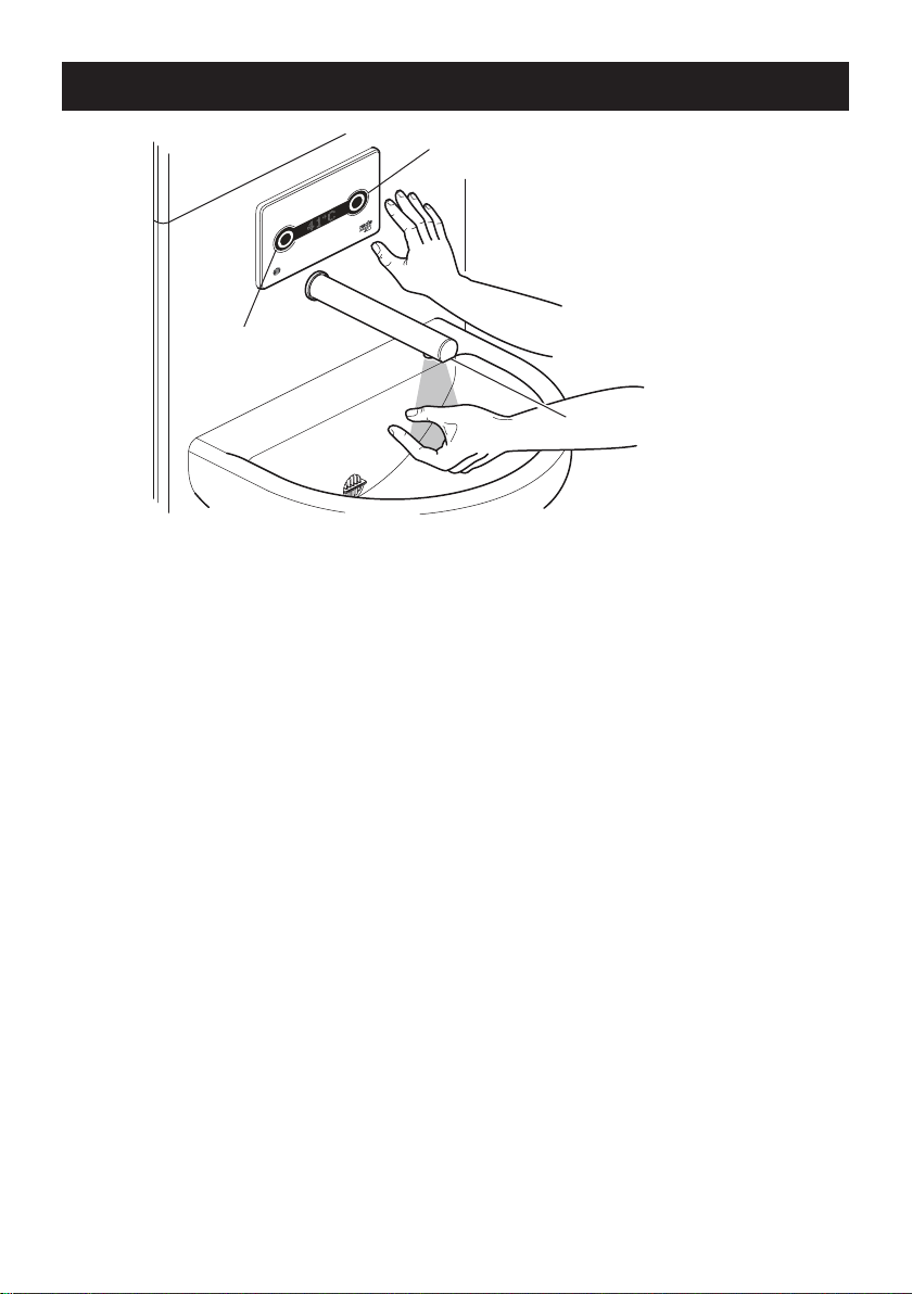
Operation ...............................................................................................10
User Modes........................................................................................10
Programming .........................................................................................13
General...............................................................................................13
Main Menu..........................................................................................15
Settings .............................................................................................. 16
Valve Setup ........................................................................................17
Set Mode............................................................................................18
Flush Setup ........................................................................................19
Set Password .....................................................................................20
Service ............................................................................................... 21
Manual Flush......................................................................................22
Disinfection.........................................................................................23
Commissioning...................................................................................24
Maintenance...........................................................................................25
General...............................................................................................25
Planned Maintenance.........................................................................25
Cleaning ............................................................................................. 26
Duty Flush ..........................................................................................26
Disinfection.........................................................................................26
Pall Filters...........................................................................................26
Filters and Non Return Valves............................................................ 27
Fault Diagnosis......................................................................................30
General...............................................................................................30
Self Diagnostic Errors.........................................................................32
Spare Parts ............................................................................................34

31108900-W2-L
Customer Care.......................................................................................36
Default Password: 1 1 1 1
User Dened Password: _ _ _ _
DMV Location:
_ _ _ _ _ _ _ _ _ _ _ _ _ _ _ _ _ _ _ _ _ _ _ _ _ _ _ _ _ _ _ _ _ _ _ _ _
ATTENTION. The Rada Acu must be commissioned in order to
activate and set-up the automatic duty ushing function. Please
refer to the following instructions to achieve this.

4
1108900-W2-L
DESCRIPTION
A panel mounted 1/2” Digital Mixing Valve (DMV) with a non touch on/off sensor
mounted in the spout and a non touch control panel for temperature control. Functions
include timed ow control, duty ush and thermal disinfection.
Suitable for HTM64 TB H6 basin assemblies for use in conjunction with clinical
procedures. Use as an alternative to TP6 in conjunction with personal washing or
hand washing.
Type 3 Valves
The sufx ‘3’ indicates that this DMV has been certied for use in UK Healthcare
premises as a Type 3 valve under the BUILDCERT TMV3 scheme.
Application
The approved designations for Type 3 Valves are as follows:
Model Designation Code
Rada Acu HP-WE
For Type 3 Valves refer to the TMV3 Requirements Manual
Key Features
• Non touch ON/OFF spout activation or timed ow control
• 3 optional pre-programmed modes and 1 user dened mode:
• Patient: Activation of the water supply via the spout sensor, ow
preset at 38°C with temperature adjustment up to 41°C and full
cold.
• Clinical: Activation of the water supply via the spout sensor, ow
preset at 41°C with no temperature adjustment.
• Surgical: Activation of the water supply via the spout sensor,
3 minute timed ow with temperature adjustment in 2 degree
increments between 35°C and 43°C.
• Free Mode (user dened mode): Activation of the water supply
via the spout sensor, ow duration adjustment up to 5 minutes,
temperature adjustment: Full Cold or 30°C to 48°C
• Programmable ‘duty ushing’
• Thermal disinfection
• D08 commissioning regime/temperature logging, an automatic cycle that
measures hot, cold and blend temperatures and displays them on the
interface.
• Valve information and usage data
Patents and Design Registration
Patents:
GB: 2 421 297
USA: 7 669 776

51108900-W2-L
SAFETY : WARNINGS
The function of this Digital Mixing Valve (DMV) is to deliver water consistently at a
desired temperature. This requires that:
1. It is installed, commissioned, operated and maintained in accordance with the
recommendations given in this Manual.
2. For Type 3 installations, DMV’s are only to be used for applications covered
by their approved designations.
3. Periodic attention is given, as necessary, to maintain the DMV in good functional
order. Recommended guidelines are given in the Planned Maintenance section
in the TMV3 Requirements Manual.
4. Using this DMV outside the specication limits given in this Manual can present
potential risk to users.
5. The electrical installation must comply to “BS 7671 - Requirements for Electrical
Installations”, commonly referred to as the IEE Wiring Regulations, or any
particular regulations and practices, specied by the local electricity supply
company.
6. The supply cable to the PSU cannot be replaced, if the supply cable is damaged
then the PSU should be discarded.
The use of the word ‘failsafe’ to describe the function of any DMV is both incorrect and
misleading. This DMV incorporates additional shut-off devices to improve the level
of safety however, in keeping with every other mechanism it cannot be considered
as being functionally infallible.
Where chlorine disinfection is practised, DO NOT exceed a chlorine concentration of
50 mg/l (ppm) in water, per one hour dwell time. Such procedures must be conducted
strictly in accordance with the information supplied with the disinfectant and with all
relevant Guidelines/Approved Codes of Practice.
Patent Applications:
Europe: 2 227 647
USA: US-2010-0282326-A1
China: CN101918743A
India: 1306/MUMNP/2010
Design Registration:
001065023-0004

6
1108900-W2-L
SPECIFICATIONS
For Type 3 installations, the supply conditions specied in section: ‘Type 3 Valves,
Application’ in the TMV3 Requirements Manual take precedence over the operating
parameters which follow.
Standards and Approvals
This Digital Mixing Valve complies with all relevant directives for CE marking.
This Digital Mixing Valve is a type 1 electronic, panel mounted control.
General
Rated Impulse Voltage Mains Supply
12 V DC & 5 V DC supply to valve
Suitability for Drinking Suitable
Connections 15 mm compression / Flat Faced Union
Pressures and Flow Rate
Maximum Static Pressure 1000 kPa (10 bar)
Minimum Static Pressure 100 kPa (1 bar)
Supply Pressure Differential Equal pressure recommended - for optimum performance
pressure must be stable
Maximum Flow Rate 6 L/min Flow Regulator Fitted
Temperatures Clinical Patient Surgical User Dened
Maximum (Blend) 41°C 41°C 43°C 43 - 48°C
Minimum (Blend) 41°C Full Cold 35°C Full Cold,
30 - 38°C
Blend (Default at start-up) 41°C 38°C 41°C 33 - 41°C
User adjustment None 38°C to 41°C
and Full Cold 35°C to 43°C Optional
Duty Flush (Factory Setting) Disabled Disabled Disabled Disabled
Minimum Blend Temperature
Differential from Hot Supply 2°C
Optimum Thermostatic
Control Range 30°C - 48°C
Cold Water Range for healthcare applications supplies should be in the range:
5°C to 20°C
Hot Water Range for healthcare applications supplies should be in the range:
50°C - 65°C
Temperature Stability ± 1°C at recommended supply conditions
Ambient Temperature Greater than 1°C, max. 40°C
Maximum Relative Humidity 95% non-condensing at 25°C
Electrical
Supply Voltage 100 - 230 V RMS 50 - 60 Hz
Maximum Load 20 W
Mains Cable Length (to PSU) 3 m
Times Factory Settings Programmable Range
Flow Time to Auto Shut-off 2 seconds 0 seconds to 5 minutes
Duty Flush Cycle 3 minutes 1 - 59 minutes
Duty Flush Waiting Time 1 Day 4h, 12h, 18h, 1d - 7d, 14d, 28d
Duty Flush Temperature 41°C 38°C - 43°C
Disinfection
Minimum Temperature 60°C
Minimum Time 5 minutes

71108900-W2-L
INSTALLATION
General
Installation and commissioning must be carried out in accordance with these
instructions, and must be conducted by designated, qualied and competent
personnel.
Before commencing, make sure that the installation conditions comply with the
information given in section: ‘Specications’.
The plumbing installation must comply with the requirements of UK Water
Regulations / By-laws (Scotland), Building Regulations or any particular
regulations and practices, specied by the local water company or water
undertakers.
Observe all local plumbing and building regulations.
Warning! Failure to achieve parallel inlet supply pipework will result in the inability
to service the mixing valve.
Do not install the Rada Acu opposite a mirror, a highly reective surface or into
direct sunlight.
Caution! The Digital Mixing Valve (DMV) must be installed in a dry area and where
it will not freeze.
Note! The DMV must be installed in an environment that provides access to the
power supply and rear box, ideally an IPS panel.
The installation of the panel assembly is not covered by these instructions.
1. The use of supply-line or zone strainers will reduce the need to remove debris
at each DMV point. The recommended maximum mesh aperture dimension
for such strainers is 0.5 mm.
2. Inlet pressure tappings which allow measurement of the inlet pressures to the
DMV under operating conditions are particularly recommended for healthcare
applications.
3. Pipework must be rigidly supported and avoid any strain on the connections.
It is important that the inlet supply pipework is parallel, therefore should the
mixing valve need to be removed the inlet pipework will remain in place allowing
easy mixing valve re-installation. Failure to achieve parallel connections will
result in an inability to service the mixing valve.
4. Pipework dead-legs should be kept to a minimum.
5. Supply pipework layout should be arranged to minimise the effect of other outlet
usage upon the dynamic pressures at the DMV inlets.
6. Inlet threaded joint connections should be made with PTFE tape or liquid
sealant. Do not use oil-based, non-setting joint compounds.
7. To eliminate pipe debris it is essential that supply pipes are thoroughly ushed
through before connection to the DMV.

8
1108900-W2-L
Front View
HOTCOLD Spout
Retaining
Nut
Make the connections to the Rada Acu
1. Connect the hot and cold water supplies to the inlet isolators, connections are:
Hot: Left, Cold: Right, when viewed from the front.
Caution! It is essential that the supply pipework is thoroughly ushed
through before connection to the digital mixing valve. Failure to do so may
result in product malfunction and will not be covered under the guarantee.
2. Tighten the compression nuts or at faced connectors.
Note! When tightening the connections, hold the inlet isolator by using a spanner
on the spanner at.
3. Connect the PSU to a 3 amp switched fused spur box (not supplied).
Warning! Isolate mains power before making any electrical connections.
Important! The PSU must be installed vertically, as illustrated.
4. The spout retaining nut is provided with screw holes for the connection of an
earth wire to comply with the Meigan Guidance Notes.
5. Go to section: ‘Commissioning’.
Rear View
Important! The PSU must
be installed vertically
PSU
Inlet Isolator
HOT
COLD
It is important that the inlet pipework
is parallel and under no strain. Failure
to achieve parallel inlet connections
will result in an inability to service the
mixing valve
Note! The use of pipe clips is recommended
in order to achieve parallel inlet pipework
connections

91108900-W2-L
COMMISSIONING
Commissioning must be carried out in accordance with these instructions,
and must be conducted by designated, qualied and competent personnel.
Notes! For Healthcare Installations, all results must be recorded.
The wearing of high visibility or uorescent jackets can cause false operation
during commissioning and programming.
1. Turn on the hot and cold water supplies and check that there are no leaks.
2. Turn on the power supply.
3. Position your hand under the ow sensor on the spout to activate the Digital
Mixing Valve, to ush out any air.
4. Check inlet pipework temperatures for correct function of non return valves i.e.
the hot water does not cross ow into the cold water supply.
5. Check that the temperature(s) and ow rates obtainable are acceptable.
6. The factory default mode is ‘Patient’, refer to section: ‘Programming’ if you
wish to change this mode.
7. Check the supply temperatures and pressures are within the range stated in
section: ‘Specications’ and carry out a performance check:
Note! For Type 3 Valves installations refer to the ‘TMV3 Requirements
Manual’, see supply conditions in section: ‘Type 3 Valves’ and follow the
procedure detailed in section: ‘Method for Commissioning Thermostatic
Mixing Valves’.
The principal means for determining the continuing satisfactory performance
of the mixing valve is the in-service test. Refer to the ‘TMV3 Requirements
Manual’.
Note! Use the commissioning mode to record maximum, minimum and blend
temperatures, refer to section: ‘Programming’.
8. Duty Flush is disabled automatically. Refer to section: ‘Programming - Flush
Setup’ for instructions on how to alter the settings.
ATTENTION. The Rada Acu must be commissioned. Please refer
to the following instructions to achieve this.

10
1108900-W2-L
OPERATION
Red Sensor (Hot)
Blue Sensor (Cold)
Spout Sensor (On/Off)
Note! The sensors are designed to operate at a distance of up to 60 mm. There is
no need for the user to touch the spout or control panel.
User Modes
The Digital Mixing Valve (DMV) has 4 different modes: Patient, Clinical, Surgical or
Free Mode (user dened), to change modes refer to section: ‘Programming’.
Patient Mode (Factory Default):
• Standby - no illumination, interface will read: ‘Non touch’
• Activation of the water supply via the spout sensor
• Water ow stops 2 seconds after the user removes their hands
• Activation will illuminate the red and blue sensors and permit temperature
adjustment
• Default temperature: 38°C
• Red Sensor temperature adjustment: 38°C up to 41°C
• Blue Sensor temperature adjustment: Full Cold
• The temperature displayed on the interface is the set temperature, this will
ash until the temperature is within 1°C of the set point. If the temperature
exceeds the set point then the interface will ash more quickly
• The product will remain in pause mode and reactivate at the pre-selected
temperature for a period of 30 seconds
• Duty Flush - disabled in this mode, but can be activated
• The maximum continuous ow time is 90 seconds, if this time is exceeded
the DMV will shutoff and return to standby

11 1108900-W2-L
Clinical Mode:
• Standby - no illumination, interface will read: ‘Non touch’
• Activation of the water supply via the spout sensor
• Water ow stops 2 seconds after the user removes their hands
• No temperature adjustment offered to the user
• Default temperature: 41°C
• The temperature displayed on the interface is the set temperature, this will
ash until the temperature is within 1°C of the set point. If the temperature
exceeds the set point then the interface will ash more quickly
• Duty Flush - disabled in this mode, but can be activated
• The maximum continuous ow time is 90 seconds, if this time is exceeded
the DMV will shutoff and return to standby
Surgical Mode:
• Standby - no illumination, interface will read: ‘Non touch’
• Activation of the water supply via the spout sensor
• The interface displays ‘Warmup’ until the set point is reached, after which
the count down timer will start, water ow stops after 3 minutes (if the set
point is not reached within 10 seconds, the count down timer will start but
the temperature will ash)
• Activation will illuminate the red and blue sensors and permit temperature
adjustment
• Default temperature: 41°C
• Temperature adjustment is offered in 2°C increments from 35°C to 43°C
• The interface displays a count down during the 3 minute ow duration
along with the temperature
• The temperature displayed on the interface is the set temperature, this will
ash until the temperature is within 1°C of the set point. If the temperature
exceeds the set point then the interface will ash more quickly
• If the spout sensor detects no presence after 30 seconds it switches off
the ow duration and returns the product to standby
• The product will remain in pause mode and reactivate at the pre-selected
temperature for a period of 30 seconds
• Duty Flush - disabled in this mode, but can be activated

12
1108900-W2-L
Free Mode
• Standby - no illumination, interface will read: ‘Non touch’
• Activation of the water supply via the spout sensor
• Water ow stops 2 seconds after the user removes their hands, unless
the product has been placed in time ow mode by the selection of ow
duration
• Flow Duration - 0 seconds to 5 minutes (if zero is selected no time ow
applies and spout activation determines ow duration)
• If the ow duration is pre-set and the spout sensor detects no presence
after 30 seconds it switches off the ow duration and returns the product
to standby
• Temperature Adjustment - Min: Full Cold, 30°C to 38°C or none, Blend:
33°C to 41°C, Max: 43°C to 48°C or none
• The temperature displayed on the interface is the set temperature, this will
ash until the temperature is within 1°C of the set point. If the temperature
exceeds the set point then the interface will ash more quickly
• If ow duration is selected the interface displays a count down along with
the temperature
• The product will remain in pause mode and reactivate at the pre-selected
temperature for a period of 30 seconds
• Duty Flush - disabled in this mode, but can be activated
• The maximum continuous ow time is 90 seconds, if this time is exceeded
the DMV will shutoff and return to standby

13 1108900-W2-L
PROGRAMMING
General
Programming via the interface is accessed by swiping/tapping the magnetic
key between the red sensor and ‘T-Logic’ symbol, this will take you to the ‘Main
Menu’.
The menus are navigated by scrolling with the blue sensor and selecting with the
red sensor.
Important! Hold your hand in front of the sensors to scroll and select (i.e. do not
‘wave’ at them).
Red Sensor
Blue Sensor
Magnetic Key
Accessing the main menu allows you to disable the Digital Mixing Valve (DMV), view
DMV information and access sub menus to perform setup and operations such as
Duty Flush, Thermal Disinfection, etc... To exit the progamming mode re-apply the
magnetic key.
If the DMV is left in the programming mode it will return to standby after 2
minutes.
The main menu is structured as follows (refer also to section: ‘Main Menu’):
‘Disable Acu’ Disables the valve sensors in order to clean the DMV or carry out
maintenance procedures.
Note! To exit the disabled state and return to the operating mode, re-apply the
magnetic key.
‘Serial No’ Displays the valves serial number.

14
1108900-W2-L
‘Usage Count’ Displays the number of times the DMV has been operated since
installation (stored within the PCB, replacing or re-programming the PCB will reset
this to zero).
‘Last Used’ Displays (in hours) the time elapsed since the last operation.
‘Settings’ Allows you to scroll through and view the current DMV settings.
‘Valve Setup’ Allows you to change the valve mode, activate the duty ush or reset
the password.
Note! This menu is password protected.
‘Service’ Allows you to perform a manual duty ush, valve disinfection, or commission
the DMV.
Note! This menu is password protected.
‘Software No’ Displays the software revision number.

15 1108900-W2-L
Serial No
Disable Acu
Non touch
De-Activated
x x x x x x
x x x x x x
x x x x x x
Version x.x
Last Used
Useage Count
Valve Setup
Service
Settings
Software No
Main Menu
Settings
Valve Setup
Service
Refer to:
Refer to:
Refer to:

16
1108900-W2-L
Settings
Settings
The settings menu allows you to scroll through and view the current valve settings.
Activate the blue sensor to scroll to the next setting, activate the red sensor at any
time to go back to the main menu.
Patient
Blend 38°C
Max 41°
Min 38°C
Full Cold Y
Duty F Off
Settings
Current Mode
Blend Temp
Min Temp *
Max Temp *
Full Cold Y/N **
Duty Flush On/Off
*Not available in ‘Clinical’ mode.
** Not available in ‘Clinical’ or ‘Surgical’ modes.
Return to ‘Main Menu’.

17 1108900-W2-L
Valve Setup
The valve setup menu allows you to change the valve mode, activate the duty
ush or reset the password, refer to menus: ‘Set Mode’, ‘Flush Setup’, or ‘Set
Password’. To exit the valve setup menu, scroll through and select exit to return to
the main menu.
Valve Setup
Set Mode
Incorrect
0 0 0 0
Flush Setup
Set Password
Exit
Valve Setup
Enter Password
Scroll through 0-9 with the
blue sensor, conrm each
time with the red sensor.
Factory Default: 1 1 1 1
Return to ‘Main Menu’.
Set Mode
Flush Setup
Set Password
Refer to:
Refer to:
Refer to:

18
1108900-W2-L
Set Mode
Patient
Clinical
Surgical
Free Mode
Set Mode
Set
Set Mode
‘Set Mode’ is accessed via the valve setup menu and allows you to change the valve
mode to any of the 3 pre-programmed modes or set the user dened ‘free mode’.
Blend 41°C
Temp Adj N
Min 30°C
Full Cold N
Return to ‘Valve Setup’.
30°C to 38°C
33°C to 41°C
0s to 5m
43°C to 48°C
Yes or No?
Yes or No?
YesNo
?
?
?
?
?
?
? =
User dened settings; scroll
through available options
with the blue sensor, conrm
with the red sensor
Max 48°C
Flow 0m 00s

19 1108900-W2-L
Enter Flow Time
(Duty Flush Cycle)
Scroll through 1 to 59 minutes
with the blue sensor, conrm
with the red sensor.
Enter Blend
(Duty Flush Temperature)
Scroll through 38 to 43°C with
the blue sensor, conrm with
the red sensor.
Enter Delay
(Duty Flush Waiting Time)
Scroll to set one of the following
values with the blue sensor:
4h, 12h, 18h, 1d - 7d, 14d, 28d
Conrm with the red sensor.
Flush Setup
‘Flush Setup’ is accessed via the valve setup menu and allows you to activate or
deactivate the duty ush feature, set the ow duration and temperature for the ush.
Flush Setup
Flow 3m
Delay 1d
Set
Flush Setup
?
YesNo
Return to ‘Valve Setup’.
Activate No
Blend 41°C ?
?

20
1108900-W2-L
Set First Digit?
Scroll through 0-9 with
the blue sensor, conrm
with the red sensor.
Set Second Digit?
Scroll through 0-9 with
the blue sensor, conrm
with the red sensor.
Set Third Digit?
Scroll through 0-9 with
the blue sensor, conrm
with the red sensor.
Set Fourth Digit?
Scroll through 0-9 with
the blue sensor, conrm
with the red sensor.
Set Password
Set
Set Password
‘Set Password’ is accessed via the valve setup menu and allows you to change
the factory default password to your own 4 digit combination.
- 0 0 0
0 - 0 0
0 0 - 0
0 0 0 -
Set Password
?
?
?
?
Return to ‘Valve Setup’.
Factory Default Password: 1 1 1 1
Note! If you change the password to your own 4 digit combination we recommend
that you record it along with the DMV location on page 3 of this guide.
Table of contents
Other rada Control Unit manuals
Popular Control Unit manuals by other brands

Homematic IP
Homematic IP HmIP-SK9 Mounting instruction and operating manual

Honeywell
Honeywell MI-DCZME installation instructions

HEROSE
HEROSE 0681 Series operating instructions

Waveshare
Waveshare SIM7600CE-T quick start guide

National Instruments
National Instruments NI 9881 Getting started guide

Digi
Digi ConnectCore 8X Hardware reference manual