Radiant Optics HotZONE HeatProjector HZE Series User manual

HotZONETM HeatProjector
HZE Series
ELECTRIC RADIANT HEATER
RADIANT OPTICS MFG., LLC
1217 1st Street
Marysville WA 98270 USA
425-806-3990
www.radiantoptics.com

Table of Contents
1.0 About your HotZONETM HeatProjector 1
2.0 Important Instructions 2
3.0 Mounting and Electrical Installation 3
3.1 Mounting
3.2 Electrical
4.0 Maintenance 7
5.0 Troubleshooting 7
6.0 Parts List and Dimensions 8
ii

1.0 About your HotZONETM HeatProjector
Congratulations on your purchase of a revolutionary HotZONETM HeatProjector from Radiant Op-
tics. The HeatProjector line of electric infrared heaters are the most efficient spot heaters on the
market today – and not by just a little bit. Our high efficiency heat “projector” is made possible by
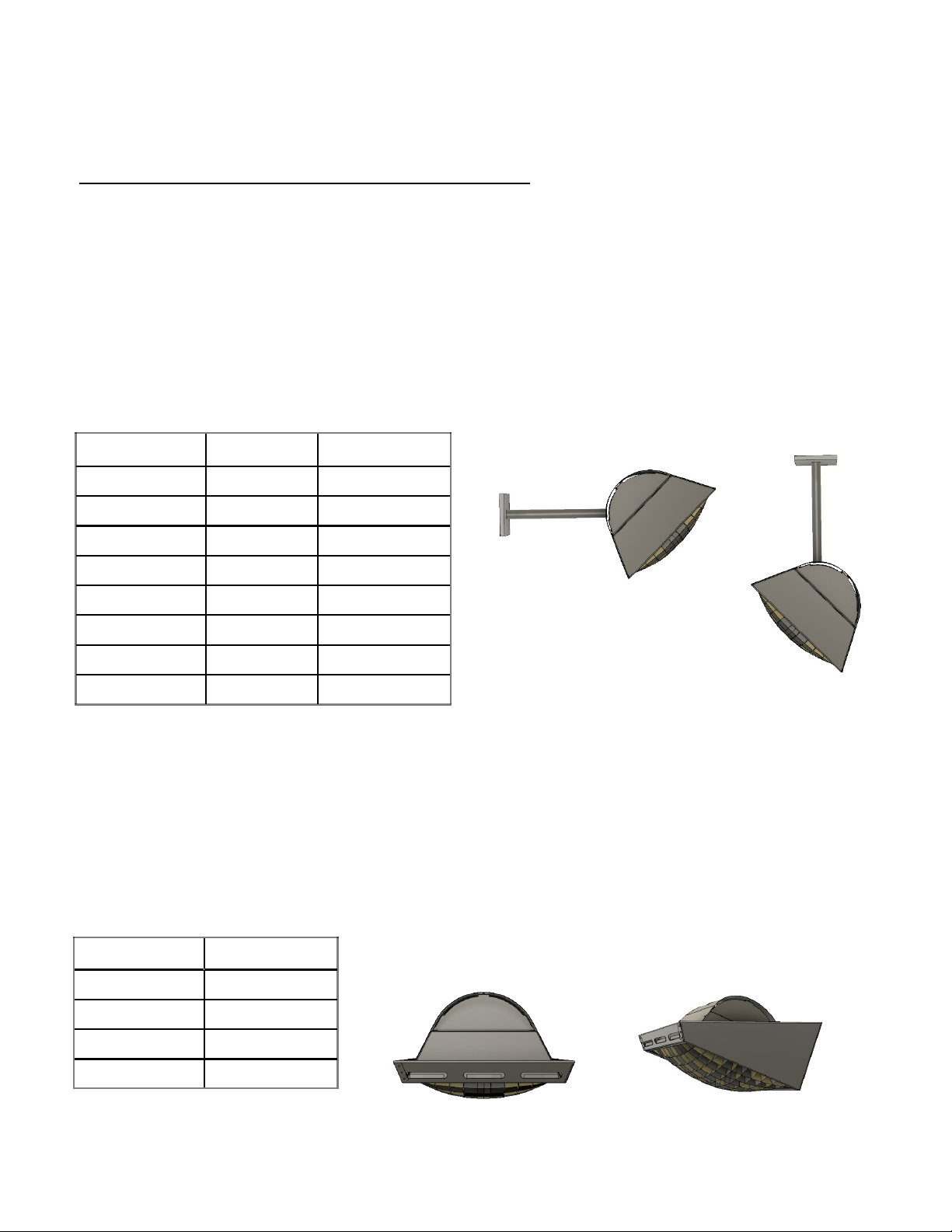
the combination of two proprietary and innovative features. Infrared heat is generated with our
unique Inverted Cone IR element and focused using our precision Compound Reflective Lens.
These act to generate, collect, and concentrate heat rays into a beam that can be pointed at a tar-
get area.
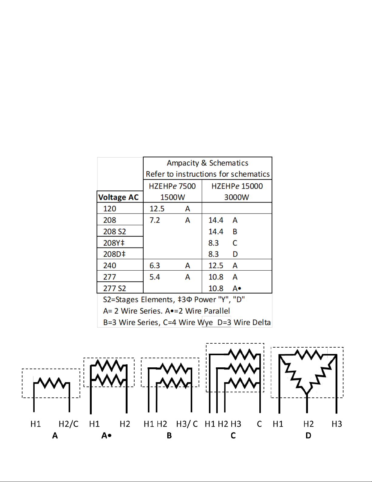
HotZONEM HeatProjectors come in 2 models: HZEHPe7500w and HZEHPe15000w
The e7500 delivers the equivalent energy of a 7500w non-lensed heater with only 1500w input;
The e15000 delivers the equivalent energy of a 15000w non-lensed heater with only 3000w input.
HeatProjectors are very low cost to run, have a smaller carbon footprint and can deliver a beam of
heat to a target over a longer distance and with a defined edge between the heated and unheated
areas.
Plan your installation by identifying the area you want to heat and how much of a temperature
increase is desired. The temperature increase depends on the power of the heater, the mounting
angle, and the distance from the target. See the HZE HeatProjector Product Guide available at
www.radiantoptics.com and refer to the Temperature Increase Map.
HotZone™ electric heaters are listed with ETL and ETLc (for Canada) by Intertek and are approved
for use in dry and wet locations.
Warranty
Radiant Optics Mfg., LLC warrants, to the original purchaser, our products to be free of defects in material or work-
manship for six months from date of purchase. Parts found to be defective will be repaired or replaced at the option
of Radiant Optics Mfg., LLC. This warranty of material and workmanship specifically excludes labor and ordinary and
routine servicing and maintenance associated with the goods sold, including replacement of the element which has
an expected service life of 2000 hours.
What is Not Covered By The Warranty
The warranty does not cover:
(1) Installations not made in accordance with installation instructions;
(2) Where the operation of the product varies substantially from our operating instructions;
(3) Malfunctions resulting from misuse, negligence, alteration, accident or lack of maintenance;
(4) Labor, loss of time, inconvenience, loss of use of the product, or other consequential damages;
(5) Products with the manufacturer nameplate removed.
The above constitutes our sole warranty. THERE IS NO WARRANTY OF MERCHANTABILITY AND
THERE ARE NO WARRANTIES WHICH EXTEND BEYOND THE DESCRIPTION OF THE FACE HEREOF.
1

2.0 Important Instructions
When using or working on electric heaters, basic precautions should always be followed to reduce
the risk of fire, electric shock, and injury to persons, including the following:
1. Read all instructions before installing or using this heater.
2. This heater is hot when in use. To avoid burns, do not let bare skin touch hot surfaces. Keep
combustible materials, such as furniture, pillows, bedding, papers, clothes, etc. and curtains
at least 4 feet ( HZEHPe7500) or 5-1/2 feet (HZEHPe15000) from the front of the heater and
keep them away from the sides and rear.
3. Extreme caution is necessary when any heater is used by or near children or invalids and
whenever the heater is left operating and unattended.
4. Do not operate any heater after it malfunctions. Disconnect power at service panel and have
heater inspected by a reputable electrician before reusing.
5. To disconnect heater, turn controls to off, and turn off power to heater circuit at main dis-
connect panel.
6. Do not insert or allow foreign objects to enter any ventilation or exhaust opening as this may
cause an electric shock or fire, or damage the heater.
7. To prevent a possible fire, do not block air intakes or exhaust in any manner.
8. A heater has hot and arcing or sparking parts inside. Do not use it in areas where gasoline,
paint, or flammable vapors or liquids are used or stored.
9. Use this heater only as described in this manual. Any other use not recommended by the
manufacturer may cause fire, electric shock, or injury to persons.
10. Burned-out elements cannot be safely repaired and must be replaced.
11. Heater must be installed according to NEC and other local electric codes.
12. Use supply wires suitable for 90oC.
13. Use high-temperature hardware (stainless steel) to connect element leads to power leads.
14. Do not install closer than Minimum Clearance to any surface.
15. Do not install less than Minimum Mounting Height from the floor.
16. Servicing should be done only while the heater is disconnected from the supply circuit.
17. ″SAVE THESE INSTRUCTIONS″
2

3.0 Mounting and Electrical Installation
3.1 Mounting
Mount the heater according to the following installation instructions:
1. Mount the heater at or above the MINIMUM MOUNTING HEIGHT (See Table on page 5)
2. Ensure the MINIMUM DISTANCE TO COMBUSTIBLES is maintained above, below and around the
heater. (See Table on page 5)
3. There are several methods for mounting your HZE HeatProjector. Each HZE HeatProjector comes
with a 3/4” EMT compression fitting and enough high temperature lead wire for mounting at the
minimum distance to combustibles.
Options:
a. Use 3/4” EMT conduit
(1) Radiant Optics recommends using the 3/4” EMT compression fitting provided to mount
your heater using 3/4” EMT conduit.
(2) Enough high temperature lead wire is provided to mount the heater at the minimum dis-
tance to combustibles: 6” for the HZEHPe7500 model and 9” for the HZEHPe15000 model.
Additional lengths of lead wire and ground wire can be attached to the wires provided using
a butt splice or connection inside a conduit body. Splices must be done per the NEC and local
codes.
(3) Comfort is best obtained with the heater off to one side and angled at 30º. Straight EMT
from heater to wall or ceiling will give a 45º mounting angle. Bend EMT as necessary to attain
desired mounting angle.
b. Use chains and flexible conduit
(1) the heater can also be hung by 4 corners using chain. Connect chain to the heater lip by
drilling 4 holes for hooks or attach chains mechanically. Position the heater to obtain a
mounting angle between 20º and 45º.
(2) Use metal flexible conduit to electrically connect leads per NEC and local codes.
c. Optional Mounting kits from Radiant Optics—Radiant Optics offers several different mount-
ing kits for both wall and ceiling mounting as well as in-ceiling mounting options (continued
on next page).
Wall Mount
Ceiling Mount
3

Optional Mounting kits from Radiant Optics
Wall and Ceiling Mounting kits
Radiant Optics offers kits to facilitate Wall or Ceiling Mounting. These kits contain:
• universal mounting subassembly includes plate for attaching to a single or dual gang junction
box of virtually any type, a cover plate, and a 3/4” EMT compression fitting;
• 3/4” EMT in length specified. Straight EMT provides a mounting angle of 45º. 30º Kits contain
pre-bent EMT to obtain the mounting angle.
• Leadwire extension for kit length specified.
In-Ceiling Mounting kits
In-Ceiling mounting can be obtained with either a flush or drop mounting kit. Ceiling spaces
must be well ventilated. Flush mount bezels are only recommended for pitched ceilings. Contact
Radiant Optics for additional information on ceiling cut-out dimensions and ventilation require-
ments.
Kit Part Number Length Mounng Angle
HZEHPWCM6-45 6” 45o
HZEHPWCM9-45 9” 45o
HZEHPWCM24-45 24” 45o
HZEHPWCM48-45 48” 45o
HZEHPWCM6-30 6” 30o
HZEHPWCM9-30 9” 30o
HZEHPWCM24-30 24” 30o
HZEHPWCM48-30 48” 30o
Kit Part Number Mounng Angle
HZEHPe7500FM 0o
HZEHPe15000FM 0o
HZEHPe7500DM 26o
HZEHPe15000DM 26o
Flush Mount Bezel Drop Bezel
3.1 Mounting (Continued)
Wall Mount
Ceiling Mount
4

The Radiant Optics HeatProjector projects a beam of energy at a target area. Items placed too
close to the heater can overheat and can catch fire. Installers must mount the heater at or
above the MINIMUM MOUNTING HEIGHT and ensure the MINIMUM DISTANCE TO COM-
BUSTIBLES is maintained above, below and around and the heater. (See Table on next page)
1. At minimum distance to combustibles, heaters will not raise the temperature of a highly
absorptive surface >90° F
2. Many heater manufacturers exaggerate the minimum distance to combustibles to exag-
gerate the performance of their heaters. Our distances are true minimums.
3. The bulk of the heat radiates from the lens of the heater in a heat beam and care must be
taken to keep combustibles out of the Combustible Avoidance Zone
3.1 Mounting (continued)
Distance to Combustibles
Top
Front Side
Top
Below
Back
5

3.2 Electrical
All wiring must be in accordance with the National and Local Electrical Codes. The heater housing must be properly
grounded. Refer to the label on the heater for model identification.
1. Install circuit protection for each heater or bank of heaters as required by the NEC and local codes.
2. Connect the service to the heater with properly sized conductors. Use waterproof conduit or flex if installed out-
doors or in wet areas.
3. Use high temperature grounding lead (identified with green tape) to connect to ground per NEC and local codes.
4. Connect service to the high temperature wires according to the wiring schematics below. Heaters have two, three
or four wires with the neutral and/or ground marked accordingly.
5. Supply heater control equipment as required to turn heaters on and off. Consider additional controls to allow the
heater to a) come on in stages for heaters with staged elements b) be dimmed or c) be controlled by timers.
6

4.0 Maintenance
HotZone™ heaters have no moving parts and require very little maintenance. We recommend the
following be done at least once a year:
• With an air hose regulated to 30 psi or less, blow off any dust and dirt that has accumulated on
the reflective surfaces of the heater and reflective lens. Accumulated dirt can degrade perfor-
mance .
• Blow off any accumulated dirt on the vent gaps of the heater and make sure the cover is not
bent such that the vent area is reduced.
• When not installed or in use, store the heater in a dry, dust-free place and be sure the lens as-
sembly is protected from any possible damage.
5.0 Troubleshooting
At full power and after two to three minutes of warm-up time, the heater element should glow a
warm orange color, similar to the color of coals in a hot fire.
If the element does not warm up at all:
• Check that the power is on at the circuit breaker and/or any installed switch or dimmer.
• Check that the element has not failed. Burned out elements normally have visible burn marks
on the face of the element. If there is no evidence of damage, and you still suspect the element,
turn off the power at the circuit breaker, disconnect the service power and check element re-
sistance. It should be between 10 and 50 ohms, depending on the element.
If the heater barely glows:
• Check any installed dimmer is turned full on and operating correctly,
• Check for the correct line voltage (under load condition).
• Confirm the heater is wired correctly. See Wiring Diagrams.
If the heater glows a bright orange-white, and heats up very quickly, the heater is receiving
too much power and will burn out very quickly if it is not turned off.
• The line voltage is too high.
Lens Repair
Heater lenses are manufactured from thin aluminum and are easily bent and damaged. Heater
performance deteriorates when the lenses are bent or damaged. In most cases the lenses can be
bent back into shape by hand or with pliers. If the lens cannot be repaired, it can be replaced.
7

1
5
4
2
3
7
6
#Description e7500 e15000 e25000
1Cover 111
2Side 222
3Lens 111
4Element Bracket 111
5Element 111
6Element Hold-down*** 122
73/4” EMT Compression
Fitting
111
Model LWHWeight Power Input
e7500 15” 15” 9” 4LBS 1500 Was
e15000 21” 21” 12” 7LBS 3000 Was
6.0 Parts List and Dimensions
Replacement Elements
The estimated life of the element is approximately 2000 hours. Information on re-
placement elements can be found at www.radiantoptics.com.
8
This manual suits for next models
7
Table of contents
Other Radiant Optics Electric Heater manuals