manuals.online logo
Brands
  1. Home
  2. •
  3. Brands
  4. •
  5. Radio Shack
  6. •
  7. Desktop
  8. •
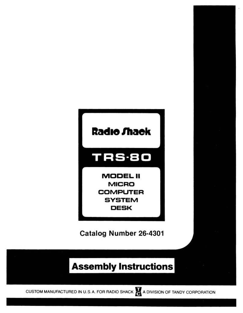
  9. Radio Shack TRS-80 User manual

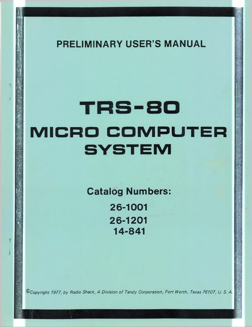
Radio Shack TRS-80 User manual

Other manuals for TRS-80

46

This manual suits for next models

4

Other Radio Shack Desktop manuals

Radio Shack TRS-80 PC-4 User manual

Radio Shack

Radio Shack TRS-80 PC-4 User manual

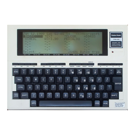
Radio Shack TRS-80 Model 100 User guide

Radio Shack

Radio Shack TRS-80 Model 100 User guide

Radio Shack TRS-80 User manual

Radio Shack

Radio Shack TRS-80 User manual

Radio Shack TRS-80 Model 4 Product manual

Radio Shack

Radio Shack TRS-80 Model 4 Product manual

Radio Shack CHESS COMPUTER 1450 User manual

Radio Shack

Radio Shack CHESS COMPUTER 1450 User manual

Radio Shack TRS-80 Service manual

Radio Shack

Radio Shack TRS-80 Service manual

Radio Shack TRS-80 User manual

Radio Shack

Radio Shack TRS-80 User manual

Radio Shack TRS-8O User manual

Radio Shack

Radio Shack TRS-8O User manual

Radio Shack TRS-80 User manual

Radio Shack

Radio Shack TRS-80 User manual

Radio Shack TRS-80 III User manual

Radio Shack

Radio Shack TRS-80 III User manual

Radio Shack TRS-80 Model 16B User manual

Radio Shack

Radio Shack TRS-80 Model 16B User manual

Radio Shack TRS-80 Product manual

Radio Shack

Radio Shack TRS-80 Product manual

Radio Shack TRS-80 Model 12 User manual

Radio Shack

Radio Shack TRS-80 Model 12 User manual

Radio Shack TRS-80 User manual

Radio Shack

Radio Shack TRS-80 User manual

Radio Shack TRS-80 User manual

Radio Shack

Radio Shack TRS-80 User manual

Radio Shack 32K InvestoGraph User manual

Radio Shack

Radio Shack 32K InvestoGraph User manual

Radio Shack TRS-80 User manual

Radio Shack

Radio Shack TRS-80 User manual

Radio Shack TRS-80 Model 3 User manual

Radio Shack

Radio Shack TRS-80 Model 3 User manual

Radio Shack TRS-80 User manual

Radio Shack

Radio Shack TRS-80 User manual

Radio Shack TRS-80 Model 100 User manual

Radio Shack

Radio Shack TRS-80 Model 100 User manual

Radio Shack TRS-80 User manual

Radio Shack

Radio Shack TRS-80 User manual

Radio Shack TRS-80 III User manual

Radio Shack

Radio Shack TRS-80 III User manual

Radio Shack TRS-80 User manual

Radio Shack

Radio Shack TRS-80 User manual

Radio Shack 1750L User manual

Radio Shack

Radio Shack 1750L User manual

Popular Desktop manuals by other brands

StarTech.com ARMSTSL manual

StarTech.com

StarTech.com ARMSTSL manual

Dell Inspiron 5720 quick start guide

Dell

Dell Inspiron 5720 quick start guide

GÜDE WERKBANK GW 6/2 XL Translation of the original instructions

GÜDE

GÜDE WERKBANK GW 6/2 XL Translation of the original instructions

Lenovo ThinkCentre M62z Vodič za uporabnika

Lenovo

Lenovo ThinkCentre M62z Vodič za uporabnika

Lenovo ThinkCentre M71z user guide

Lenovo

Lenovo ThinkCentre M71z user guide

Fujitsu ESPRIMO C7xx operating manual

Fujitsu

Fujitsu ESPRIMO C7xx operating manual

Bosch DCU 130 operating instructions

Bosch

Bosch DCU 130 operating instructions

Zotac VR GO quick start guide

Zotac

Zotac VR GO quick start guide

HP 260 G2 DM Product End-of-Life Disassembly Instructions

HP

HP 260 G2 DM Product End-of-Life Disassembly Instructions

Sony VAIO VGC-LS21 Specifications

Sony

Sony VAIO VGC-LS21 Specifications

HP ProOne 400 G1 specification

HP

HP ProOne 400 G1 specification

IBM PS/2 60 Hardware maintenance service

IBM

IBM PS/2 60 Hardware maintenance service

Acer Aspire SA60 Service guide

Acer

Acer Aspire SA60 Service guide

Lenovo ThinkCentre M71z Uživatelská příručka

Lenovo

Lenovo ThinkCentre M71z Uživatelská příručka

IBM Aptiva 2198 reference guide

IBM

IBM Aptiva 2198 reference guide

Sony PCV-LX810 - Vaio Slimtop Computer System reference manual

Sony

Sony PCV-LX810 - Vaio Slimtop Computer System reference manual

Dell Precision U3525 Quick reference guide

Dell

Dell Precision U3525 Quick reference guide

MicroTouch IC-215P-AW2 user guide

MicroTouch

MicroTouch IC-215P-AW2 user guide

manuals.online logo
manuals.online logoBrands
  • About & Mission
  • Contact us
  • Privacy Policy
  • Terms and Conditions

Copyright 2025 Manuals.Online. All Rights Reserved.

TRS-BO®
MODELm
MICROCOMPUTER
•
ervlce
Catalog
Numbers
26-1061/1062/1063
/
CUSTOM
MANUFACTURED
IN U.S.A.
BY
RADIO
SHACKl!A
DIVISION
OF
TANDY
CORPORATION
SECTION
NUMBER
II
'"
IV
V
VI
TABLE
OF CONTENTS
INTRODUCTION
..
System Overview
DISASSEMBLY/REASSEMBLY
..............••...
Disa5Sembly
.................•••••...••.•..
Reassembly
...........................••..
CPU CIRCUIT BOARD
..•...••
~
•..••••••....•..
Technical Description
.......•.....•.••••..•..
Video Sync Circuits
....•.•..............••.
Processor
...........••••••••••••....•..
RAM
...............•...........•.••..
Addrcs.s Decoding
........••...............
Memory Map
..........•••••••••.........
10
PORT Description
......•••..•.•••••••..
Video .
Keyboard
....................•.........
Cassette Interface
..................•......
line
Printer
and
Real Time Clock
.......••••••.
10
Bus
•.............................•.
Adjustments
and
Jumper
Positions .
Model
III
10 Bus Detailed Description
....•......
Model
III
PORT Bits
................•••.•..
CPU
Module Parts List
.................••••••.
FLOPPY DISK INTERFACE .
Technical Description .
Control and Data Buffering .
Non ·Maskable Interrupt Logic .
Drive Select Latch and Motor
On
Logic .
Wait State Generation and WAITIMOUT Logic
Clock Generation Logic .
Disk Bus Selector Logic .
ReadlWrite Data Pulse Shaping Logic .
Disk Bus
Output
Drives .
Write Preoompensation and Clock Recovery Logic
Floppy Disk Controller Chip .
Adjustments
and
Jumper
Options .
Floppy Disk Interface
PC
Board Parts List , .
RS-232C CIRCUIT
BOARD.
. .
RS-232C Technical Description
.........•••••.
Pin
·Out
Description .
.••••....•..•.
Port and Bit Assignments .
RS·232C
PC
Board Parts List
.....•••••.......
POWER SUPPLY . . . . . . . . . . . .
..••.•.
Functional Specifications
.......•••••..••.••••.
Troubleshooting.
. .
......•..••....••.•.
Set-Up
Procedures
.....................••••.
Visuiliinspec.:tion
.........................•.
Surt-Up
. . .
...................••..
No
Output
..............•••••.•••..
Perfonnilnce Test
................••..•..
Power Supply
Component
ViIIlues
............•••.
PAGE
NUMBER
1
3
5
7
9
11
13
13
13
13
14
"
15
16
17
17
,.
,.
,.
19
21
25
.,
.3
.3
43
43
44
44
44
44
44
44
45
45
49
53
55
56
57
62
65
67
67
67
67
58
58
69
70
SECTION
NUMBER
VII
VIII
IX
TABLE OF CONTENTS (Cont'd)
VIDEO MONITOR .
..........•...
_ _ .
Functional Specifications .
.................•...
Se...,ice Adjustments .
ILLUSTRATED PARTS CATALOG
Illustrated
Parts
Catalog
Parts
list
MINI·DISK DRIVE .
General Description
.............•...........
Introduction
...............••...........
Important Notice
........•••..............
Physical Description
.......•..•............
Functional
Desaiption
........•..•.........
Interface Connections
........•.•••.........
Physical Checkout
...........••.•.........
Mounting
the
Disk Drive
.......••.•.....
Resistor Termination .
.........••.•.........
Flat Ribbon Cable Assembly .
Theory
of
Openrtion .
Introduction .
Organization
of
the
Disk Drive .
Functional Block Diagram Description .
Indell Pulse .
Write
Protect .
Track 00 Switch : .
Spindle Drive .
................•.•......
Positioner Control .
Data Electronics .
..........••.•...........
Data Recording .
Data Reproduction .
Operation .
Interface Electronics Specifications
......•......
Input
Control Lines .
SELECT Lines
IDS'-
-
DS4-)
.
Drive Motor Enable (MOTORQN) .
Direction and Step
(DIA-)
(STEP-' .
Compensated Write Data (CWO)
..•.....
Write
Enable (WG-) .
Side Select (SDSE
L)
.
Output Status .
Index Pulse
liP')
.
TRACK OOITAKO-j .
.....•......•.........
Write
Protect (WPRT', .
Read Data
(RD-)
.................•.......
Maintenance .
Physical
Oesaiption
of
the
PC
Boards .
Circuit Board Test Points .
Option Select .
Input Line Terminations
....••.............
Pr
...
entive Maintenance
..
_
.......•••..........
Cleaning
the
Head
............••...........
Alignment
anet
Adjustment .
Drive Motor Maintenance .
Carriage
Movement Check .
Head Radiel Alignment/CE Alignment .
Track
013
Alignment .
Index Sector Adjustment .
Head
Amplitude/Compliance
Oleck
.
PAGE
NUMBER
73
7S
77
79
8.
91
93
93
93
.3
93
93
94
9.
9.
9.
97
97
97
97
97
97
97
97
97
98
..
..
101
101
101
101
101
101
101
101
103
103
103
103
103
103
lOS
lOS
lOS
lOS
lOS
108
108
108
108
108
109
110
110
111
SECTION
NUMBER
TABLE
OF CONTENTS (Cont'dl
PAGE
NUMBER
FIGURE
NUMBER
FiNI
Check .
Disk Controller Board Parts List .
SalVo Board Parts List (Non-Linear)
.......••.
Servo Board Parts
list
(linear)
..
.
....•....••..
Illustrated Parts Catalog Parts
Lin
.
LIST
OF
ILLUSTRATIONS
TiTlE
SECTION
1-
INTROOUCTION
TAS.aO Model
III
Block Diagram .
SECTION
III
-CPU CIRCUIT BOARD
111
112
118
117
119
PAGE
NUMBER
4
1
2
3
4
4
5A
58
5C
5D
5E
5F
5G
5H
5J
5K
1
2
2
3
CPU
Timing Diagram. . . . . . . . . . . . . . . . . . . . . . . . . . . . . • . • . . . . . . 13
Video Timing Diagram. . . . . . . . . . . . . . . . . . . . . . . . . . . .
••
• . . . . . . 16
10 Bus Timing Diagram
..
. . . . . . . . . . . . . . . . . . . . . • • . . . • • • • • . . .
20
CPU Printed Circuit Board -Component
Side.
. . . . • • • . • • . • • • • • • .
..
23
CPU Printed Circuit Board _Circuit Side . . . . . • . . . . .
24
Model
III
CPU Schlml"tic Diagram -
Video and Horizontal Sync
Circuit!>
. . . . . . . . . . . . . . . . . . . . . . • • .
..
31
Model
III
CPU SChematic Diagram -Processor Section . . . . . • • . . • • • .
..
32
Model
III
CPU Schematic Diagram -
RAM
Section.
. . . . . . . . . . . • • • .
..
33
Model
111
CPU Schematic
Di"gram-
Address
De"coding
Section
............................•....
34
Model
III
CPU
Schematic Diagram -Video
section...
........••..
..
35
Model
III
CPU
Schematic Diagram -Keyboard
Section.
. . . . . .
•••.
•.
. . 36
Model
III
CPU Schematic
Diagram-
Cassette Interface
Section.
. . . . . . . . . . . . . . . . . . . . . . . . . . • . . . .
..
37
Model
III
CPU
Schematic Diagram -
Line Printer and
Real
Time Clock Section
..
. . . . . . . . . . . • • • • • . • . . .
38
Model
11/
CPU Schematic Diagram -I/O Bus Section
.......•.•......
39
Model
III
CPU Schematic Diagram -
RS·232C Interface and FDC Interface
Connections.
. . . . • • • • • • • • • .
..
40
SECTION
IV
-
flOPPY
DISK INTERFACE
FOC Board to
CPU
Board Signal
Description.
. . . . . . . . . • • • • • . . . . . . .
46
Floppy
Did<
Interface
PC
Board -Component Side
..........••...
47
Floppy
Dilik
Interface
PC
Board -Circuit Side
...........•••.....
48
Model
III
Floppy
Disk
Interface
SChematic...
...
....•..•.••....
51
FIGURE
NUMBER
1
,
,
3
LIST OF
ILLUSTRATIONS
(Cant'd)
TITLE
SECTION V-R5-232C CIRCUIT BOARD
R5-232C Board
to
CPU Board Signal Description
AS·232C
PC
Board -
Component
Side
RS·232C
PC
Board -Circuit Side .
Model
til
RS·232C Schematic Diagram .
SECTION VI -POWER SUPPLY
PAGE
NUMBER
5.
60
61
63
1
,
3
•
Ten
Set-Up . . . . . . . . . . . . . . . . . . . . . . . . . • • • . . . . . . . . . . . . . .
..
67
02
Coll&ctor Waveform . . . . . . . . . . . . . . • . . . • • • . • . • • • • • . 68
02
Bue
Waveform . . . . . . . . . . . . . . . . • • . • • • • . . • . • • . . .
68
Power Supply 5ct1ematic Diagram
..•••
, . . . . . . .
71
SECTION
VtI-
VIDEO MONITOR
1
,
3
Video
Monitor
Printed Circuit Board
.......................•...
Deflection Yoke Assembly .
Video Monitor Assembly Sd1ematic Diagram
...........••..••.•..
SECTION VIII -ILLUSTRATED PARTS CATALOG
76
77
78
1
,
3
•
5
1
1A
2
3
•
5
6
7
8
8
10
11
12
13
"
15
16
17
18
18
,.
20
20
Outer
Case
Assembly.
..................... .........
..
81
Case
Top
Assembly.
...........................•••••....
..
82
Base Plate Assembly
.......••...••.•••.••••...•...........
83
Metal Chassis Assembly
..
. . . . . . . . . . . . . . . . . • . . . . . . . . . . . . .
84
Disk Drive Assembly . . . . . . . . . . . . . . . . . • . . • . . . . . . . . • . .
..
85
SECTION
IX
-FLOPPY DISK DRIVE
PC Board Component Locations (Logic Board) . . . .
..
........
..
94
PC Boord Components Locations (servo Boards)
..............•....
95
Resistor
Termination.
. . . . . . . . . . . . . . . . . . . . . . . • • . • • • . . • . . .
..
96
Cable Assembly -
Connector
Pin Removal Chart
....••.•••••.......
96
Funetional Blode Diagram
98
FM
Recording
.............................•..•••.•.•.
98
Write Timing
Diagram.
...
..
. . .
..
...............
.•
.••
.100
Read Timing Diagram .................... .......
100
Interface
Configuration..
. . . .
..
. . . .
..
. . . . . . . .
•.
. . . .
..
. . . . 101
Logic Board Test Points and
Connector
Locations
....••.••••••••.
106
Servo Board
Comector
Locations..
. . . .
..
...
..
. .
..
.
..
.•.
..
. . 107
"Cat's
Eyes"
Panern
..
..................................
..
109
Radial Ad;ustmeot
..................•..•••••........•....
109
Track
tJ0
Stop
Adjustment . • • • • . . . • • • • • • • • . • • • . . • .
110
Index Sector Timing
..
. . . . . . . . . . . . . . . . . . • . • . • • . . . . • . . . . . 110
Index
Adjustment.
. . . . . . . . . . . . . . . . . . . . . . . . . . . . . . . 110
Upper Arm and Carriage
.................••••.............
111
Illustrated Parts Catalog -Exploded View
.....•••••••.••.•••....
118
Mini·Disk Drive Schematic (Sheet
11
........••.•••••.•••••.•..
120
Mini-Disk Drille Schematic (Sheet 2)
..........••••.............
121
Servo Board Schematic
.....................•..............
122
Mini·Disk Drive Schematic (new board) ............
••••.
. . 123
Mini·Disk Drive Schematic (new
boardl
....•
,..................
124
TABLE
NUMBER
LIST OF TABLES
TITLE
SECTION V - R5-232C CIRCUIT BOARD
PAGE
NUMBER
1
2
1
2
BRG
Programming Table .
SECTION
VI-
POWER
SUPPLY
Load Board
Values.
...... .
............••••..•..•....
Voltage and Ripple Specifications
....
SECTION IX -
MINI·DISK
DAIVE
Interface Connector Pin Assignments
.............•...
Power Connector
Pin
Assignmcots
...............•.••.
55
58
59
'02
'02
SECTION I
INTRODUCTION
,
SYSTEM OVERVIEW
The Aadio 5tIack TASSO Model
III
Miaocomputer
is
an enhanced
venion
of
Aadio 5tIack's popular
TRsaO
Microcom-
puter (Model
n.
The TAs-80 Model
III
is
sohware
eompatible with
the
Modell
§()
thillt
ownenof
either system can take
adll8ntilge
of
the large number
of
programs available.
Features
of
the TAS-80 Model
III
which are common to the TR5-80
Modell
include:
•Availability
of
Level
lor
Level
II
BASIC
in
ROM
•
Full
size typewriter style keyboard
• A 12-inch video display
•Built·in cassette interface
•Character display
of
16 lines
of
64
characters
•Graphics under control
of
BASIC (128 H x 48
VI
• UL reoognized construction
In
addition. tne Model
III
has
the
following standard features:
•12-«.ey numeric keypad for rapid
entry
of
numbers
•
Augged
cabinet housing keyboard. electronics, video display. and power supply
•Direct drive video monitor for improved resolution
•Internal power supply
•Parallel printer port for
USll
with Aadio 5tIack printers
several
other
features are available when
Level
II
BASIC
is
used; features such as: real time clock, upper and lower case
characters,
RAM
internally expandable to 48K bytes, I/O
l)Or\
for peripheral expansion. and cassette interface available
with
500
aoo 1500 baud rates.
Optional peripherals for the TAS-aO Model
III
include disk drives (two built·in, two external) with double density for
increased storage capacity. and ahuilt·in R5-232 serial interface for communications and peripheral interface.
The
Block Diagram shows
the
various internal components and connections
of
the Model
III
Microcomputer.
3