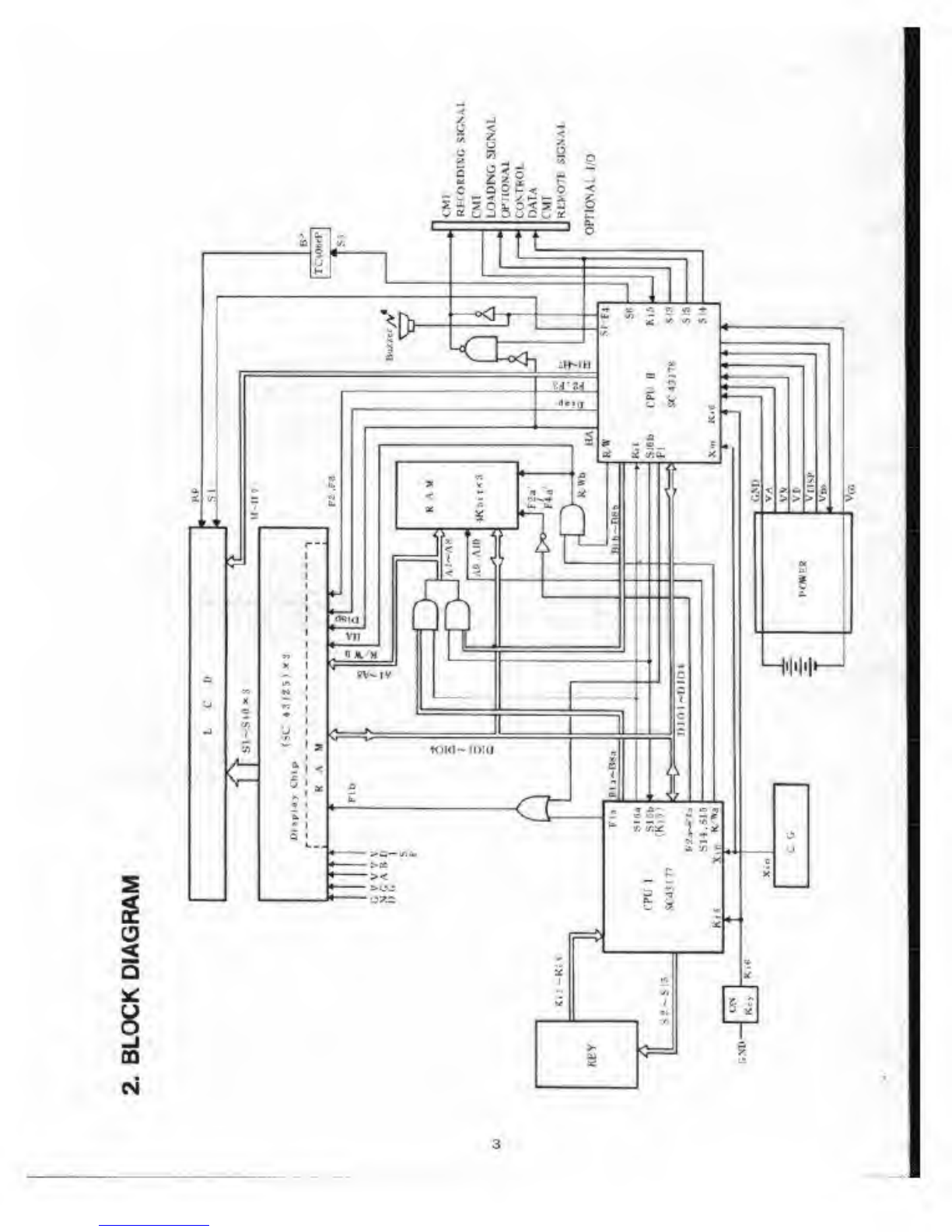
System configuration (see the s/stem block diagram)
The system consists of (he following components:
1. CPUI(SC43I77)« I
2. CPUU(SC43l7S)x I
3. 4K-bltRAM(rOM4)*x3)
4. Display chip (SC43I23 «3. with Duilt-in RAN)
5. 2ANDga(e<TC4011UrJP*l)
6. 2AMJ20H(K4yivUCx I)
7. lnvwter(TC4069BPx I)
S. Quard Analog Switch Miiltiplover (TCdOAtBP)
o. ITD(34-di8it FhMdot LCD)
10. Key
11. Crystal (CSB2560)
Brief overview of CPU Iand CPU II
The CPUs are provided with internal ROM.and the CPUs have ihe following assignments
CPU I
Key input rostine
Acknowledgement of the remaining
program
One instruction to one program step
additional incoiporatton
Interpreter:
Pio&aiii execute italciiuul
CdSSCtlt tuillfol MdUlUClil
Cummand ilateimnt
Pointer control (leserved)
v-irii'i lit mrinutl opentnn
Piw.resumt control
Clouk Hup centred
CPU
Display proceHing routine
Input buffer
Cunipuiaiional result
trr'T
Ai >Uim>tit H'jlirc
Character geritiatoi
(arctic routine
Print tontine
Qj,uei
Rprngnitlor: nf printer (reserved)
I'oiver "t I
Clojk nop
•The CPU Iiu.ii;;i, ia read key-ii data ur read (tie instruction to be execute*] fiom the RAM, and decides what is to be
don* (or Iho loiuitl of aritlunebco': operation* (i.e., control of arithmetic sequence, memorieingof arithmetical Jots, and its
-i I '.or interpret the cyntnx of the BASIC instruction for deciding what is to be executed, or determine* and prepare*
the information lo be displayed, but CPU" Idoei not perfiwm any execution By itself. Il only arranges ihedata and inlorma-
tlon in proper sequence and acts to provide instruction codelo the fPL II via the buffer. On Uteothet hind. CPU Dconstant-
ly receives execution instructions from CPU Ivia the transfer buffer and executes operations pei each infraction or ex-
changes data, depending on the situation. Although it shares eA«.uiio>! fum-lions and tieifoiai* some auxiliary CPU rolcs.it
does net perform any decision by itself.
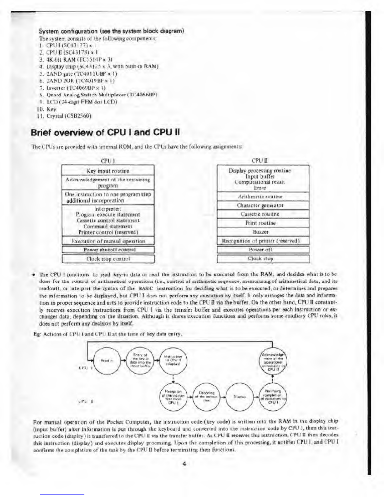
Eg- Actions of CPUIand tPU Uat the lime of key data entry.
irt
kvv u
For ni ui'. il operation of ihe Pocket Computet, the uislructlon code (key code) awritten (mo the RAM in the display chip
(Input buffer) after Information is put through the kcybwitd and converted into the instruction code by CPU I, then this inst-
ruction code (display! is transferred to thoCPt-111 vis the transfer butler. As CPU Disceivei this inctmciion. CPU II ther decodes
this imtmction <display) and executes dlisplay processing Upon the completion of this processing, it notitlei CPU I, and CPU I
confirms the completion of the vak hy ihe CPU 11 before lermimtirg their function!.