manuals.online logo
Brands
  1. Home
  2. •
  3. Brands
  4. •
  5. Radio Shack
  6. •
  7. Desktop
  8. •
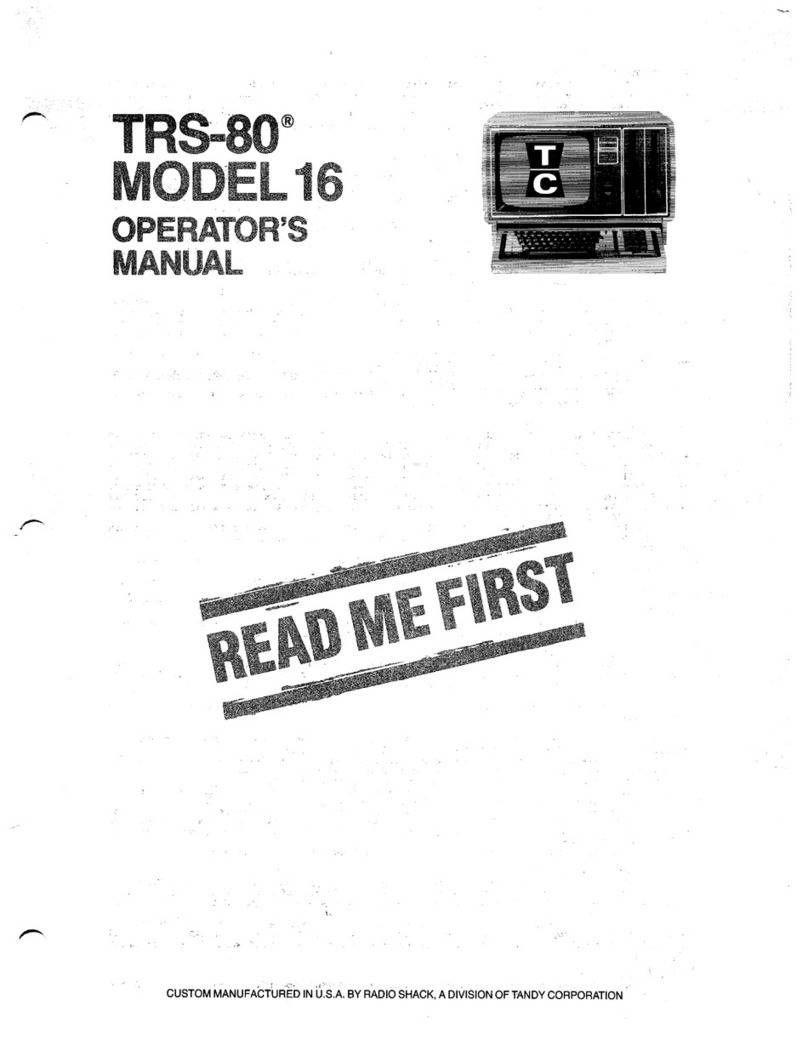
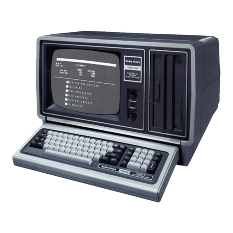
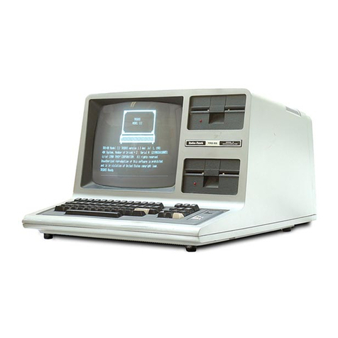
  9. Radio Shack TRS-80 Model 16 User manual

Radio Shack TRS-80 Model 16 User manual

•
ervlce
CUSTOM MANUFACTURED
IN
U.S.A. BY RADIO SHACK. ADIVISION OF TANDY CORPORATION
•
----------TRS-SO
@
TRS-S'-
Model
16
Service
Manuai
Copyright.
1982
Tandy
Corporation
AlI
Rigbts
Reserved
Reproduction
or
use,
without
express
written
permission
from
Tandy
Corporation,
of
any
portion
of
this
manual
i5
prohibited.
Whi~e
reasonable
efforts
have
been
ta
ken
in
the
preparation
of
this
manual
ta
assure
its
accuracy,
Tandy
Corporation
assumes
no
liability
resulting
from
any
errors
or
omissions
in
this
manuaI,
or
from
the
use
of
the
information
obtained
herein.
--------Itadlelllaell--------
•
•
•
•
Model
16
----------TRS-SO
'"
Service
llanual
COntents
Introduction
5
3/Troubleshooting
.....
...................................
...................................
Operation.
.11
.37
•••••
7
.....................................
of
2/Theory
l/Specifications
4/Prin
ted
Circui
t
Boards
41
5/parts
List.
..........................................
..
.
61
6/Schematics.
...........................................
...
75
•
i
•
1tadle1Mell--------
3
•
Model 16
_____________
TR5-BO
e
s_e_r
__
v..:i..:c::e~
...
=Dual::::~_
•
•
i
ltadlellllleli------
•
- 4 -
----------TRS-ao.,
----------
•
Model
16
Service
MaIlual
•
•
Introduction
The
TRS-Sg
Model
16
cantains
two
microprocessors
--
the
MC68~~~
and
the
Z-8~A.
This
allows
both
8-bit
and
16-bit
selectable
operation.
This
manuai
will
provide
information
primarily
on
the
6a",
aide
of
the
Model
16.
For
Z-ag
information
that
has
not
been
included,
refer
ta
the
Model
II
Technical
Reference
Manual
or
the
Model
II
Service
ManuaI.
---.......:'-----ItadIeIllaell--------
- 5 -
----------TR5-S0.,
---------
•
Mode1
16
Service
Manual •
---------ItlIdIeIllaeli---------
- 6 - •
----------TR5-BO
..
---------
•Model
16
Service
Manual
•
•
•
•
1/
Technical
Specifications
Proce8S0r
Module.
The
TRS-8~.
Model
16
ia
a
dual
processor
system.
One
proce~sor
i5
dedicated
ta
Input/Output
tasks,
while
the
other
ia
dedicated
ta
high-level
language
tasks.
MC68",
CPO
Board
The
MC68
•••
CPU
Board:
Provides
16-bit
operation
for
high-level
language
tasks
.
Supports
direct
access
for
up
ta
7
megabytes
of
memory •
Supports
8
levels
of
vectored
interrupts.
Supports
4
levels
of
fixed
priority
bus
arbitration.
Supports
a
Zsg
ta
MC68ggg memory
interface
controller.
The
major
components
of
the
MC68ggg
CPU
Board
include
the:
MC68
•••
CPU.
AM9519A
Interrupt
Controller.
128K/256K-Byte
Meaory
Board
,
The
128K-byte
Memory
Board
provides:
Space
where
an
optional
128K-bytes
of
memory
cao
be
installed.
Optional
byte
parity
checking
and
detection
logic
•
option
selecting
ta
map memory
on
AnY
256K
boundary
within
7-Meg memory
space
•
--------ItadIe.n.aeIÏ--------
- 7 -
----------TRs.ao
<Il
_
za,
CPU
Board
•
Model
16
Service
Manual •
The
za~
CPU
Board:
•
•
•
Provides
primary
DMA
channel
--
memory
ta
memory,
1/0'
ta
memory,
or
memory
ta
1/0.
Supports
Z8~
Mode 2
vectored
interrupts.
Supports
dual
RS-232
Interfaces.
Supports
bath
asynchronous
and
synchronous
communication
schemes.
Provides
boot-strap
firmware
which
resides
in
the
lower
2K
of
the
64K
address
space.
(Boot-strap
firmware
15
switched
out
of
the
address
space
after
bootup
la
complete.
)
The
major
components
of
the
CPU
Board
include:
•
•
za~-A
CPU.
Z8~-A
eTC.
za~-A
DMA.
za~-A
SIO.
•
•
•
Ploppy
Diak
Controller/printer
Interface
Board
The
Floppy
Disk
Controller
(FOC)
Board
provides:
Software-selectable
double-
or
single-density
operation.
TwO
independent
drive
interfaces,
one
for
the
interna!
drives
and
one
for
the
external
drives.
Adjustable
write
pre-compensation
from
i
ns
to
35~
ns.
Fast
parallel
printer
interface,
capable
of
generating
an
interrupt
when
the
prioter
can
accept
another
character.
'
The
major
compone~ts
of
the
FOC
Board
include:
•
•
za~-A
PlO.
WD1791.
WD1691.
WD2143.
•
--------ItadIeIllllell--------
- a -
64K-byte
Memory
Board
----------
TRS-Sa"
---------
•
Model
16
Service
MaDu.l
•
The
64K-byte
Memory
Board
provides
jumper
option
selection
for
one
of
15
memory
pages.
Its
major
components
are
4116
16K x 1
dynamic
RAMs.
Video/Key
board
Interface
Board
The
Video/Key
board
Interface
Board
provides:
24
lines
of
either
89
or
4g
characters.
Programmable
timing
parameters.
seriaI
bit
stream,
processor
interrupt.
Its
major
components
are
an
MC6845
CRT
controller
and
2114
static
RAMs.
Motherboard
18-s1ot)
The
8-slot
Motherhoard
provides
89
conductor
paths
which
distribute
regulated
power
and
provide
signal
inter-
connection
for
the
system
boards.
Option.l
Boards
Optional
boards
include
the
following:
Hard
Disk
Interface
Board
--
16K
RAM,
bank-selectable.
Interfaces
te
intelligent
high-speed
eontroller.
l
to
4
hard
disk
drives
supported.
Major
eomponents
inelude
4116
16K-by-l
dynamic
RAMa,
Z8~-A
CTC.
High-Re~olution
Graphies
Board
--
64g
x
24g-pixel
resolution.
Direct
overlay
of
alphanumeries
and
auto
reverse.
Options:
Register
user-programmable
for
blanking
graphies,
seleeting
wait
states,
and
contro11ing
the
X
and
y
address
pointers.
Option:
Control
and
Data
Registers
are
port
mapped.
Address
pointers
increment
or
decrement
automatica11y
after
a
read
or
write
of
memory.
Major
eomponents
inelude
4116
16K-by-1
dynamic
RAMs.
--------IIlIdIeIllaeli---------
••
Arenet
Interface
Board
--"Local
Area
Network
supports
up
to
255
users
on
the
same
network
with
a
transmission
capability
of
up
to
2~~9
feet
and
a
data
rate
of
2.5
- 9 -
K-bits.
Butter
Memory
ia
segmented
ioto
four
pages
of
256
bytes
each.
Its
major
components
include
a
eus
tom
151
device
and
2114
static
RAMa.
•
Model
16
----------TRs-ao
..
Service
llaDual •
128K/256K
Memory
Board
--
128R
or
256K-bytes
of
dynamic.
RAM,
depending
upon
whether
one
or
two
RAM
banka
have
been
installed.
Byte
parity
checking
and
detection
logic
ls
also
provided
as
an
option.
The 128X/256K
Memory
soard's
major
components
include
MCM6665
64X-by-l
dynamic
RAMa.
CRT
Display
Module
The
CRT
display
module
has
basically
the
same
specifications
as
the
Model
II
video
monitor:
however,
increased
bandwidth
(22
MHz)
is
provided
for
a
sharper
display.
Resolution
la
typically
9gg
lines
at
center
sereen
and
75g
lines
in
the
corners.
A
green
P5
phosphor
CRT
ls
provided.
Ploppy
Disk
Drives
The Model
16
can
have
one
or
two
Tandon
Thin-Line
drives,
double-
or
single-sided
media,
single-
or
double-density,
built
into
the
Computer.
Power
Supply
The
power
suppl
Y
requirements
are:
•
•
•
+5v
@
13.36
A•
+l2v
@
2.5
A.
-12v
@
2f1f1
MA
•
+24v
@
1.
7 A• •
---------ltadlelllaeli---------
-
lf1
-
----------
TRS-BO"
---------
•Model 16
Service
Manuai
2/
Theory
of
Operation
Model
16
CPU
Board
Theory
of
Operation
The
theory
of
operation
for
the
CPU
board
has
been
broken
up
ioto
severa!
major
sections,
each
correspondinq
ta
a
109ical
unit
of
LB!,
MSr,
and
55!
parts
on
the
CPU
board.
They
are
as
follows:
•
•
•
•
•
•
Section
1.0
Section
2.0
Section
3.0
Section
4.0
Section
5.0
Section
6.0
Section
7.0
Section
8.0
Section
9.0
Section
10.0
Central
Proceaaing
Unit
(CPUl
Interrupt
Logic
Z80
to
68000 Memory
Interface
Circuitry
Memory Management
Circuitry
Bus
Arbitration
Logic
Data
TcaDsfer
Acknovledge
Loqic
68000
1/0
Decoding
and
Strobes
Clock
Logic
Refresh
Logic
Bus
Errer
Loqic
•
Note:
The
terms
"assertion"
and
·negation"
are
used
ta
avold
confusion
when
talking
about
active-high
or
active-low
signaIs.
"Assert"
or
"assertion"
iB
used
ta
indicate
a
teue
or
active
state,
regardles8
of
its
high
or
low
potential.
"Negate"
o~
"negatioo"
indicates
a
faise
or
inactive
state.
Section
1.0'
Central
Processing
Unit
(CPO)
The
Model
16
board
uses
the
Motorola
MC68000
chip
which
contains
16
data
lines,
23
address
lines,
and
20
control
lines.
The
data
lines
(KOO-K01S)
are
interfaced
ta
the
bus
via
tranceivers
U1S
and
U16
(AMO
8303'5).
When
high,
the
CO
control
line
(pin
9)
on
the
transceivers
tri-states
the
data
bus.
This
signal
is
driven
by
Bus
Grant
Acknowledge
(BGACK),
which
indicates
that
a
device
other
than
the
68000
CPU
is
bus
master.
--------ItadIeIllaelÎ--------
-
11
-
----------TRS-SO"
----------
The
TR
control
line
(pin
lIon
the
83~3IS)
contraIs
the
direction
the
transceiver
is
painting
and
i5
driven
by
Data
Bus
Transmit/Receive
(DBTR).
(See
the
upper
left-hand
corner
of
Sheet
3
of
the
CPU
schematic.)
The
active-low
output
DBTR
from
U49
pin
19
enables
the
data
receivers
during
an
off-board
interrupt
acknowledge
sequence
(INTAKL6*)
or
during
a
cead
frorn
externa1
memory.
•
Model
16
Service
Manual •
The
active-high
state
of
DBTR
enables
the
data
drivers.
It,
therefore,
follows
that
the
data
receivers
are
disabled
when:
A
cead
or
weite
is
in
progress
from
the
Interrupt
Controller
chip
(INTCS*).
A
board
interrupt
acknowledge
sequence
iB
in
progres5
(PRIORINTAK*)
•
A
weite
ta
externa1
memory (R/W*)
occurs.
It
should
he
noted
that
the
CO
control
line
overrides
the
TR
control
line,
and
that
both
drivers
and
receivers
are
disabled
(tri-stated)
if
BGACK
is
asserted.
Address
Linea
The
68~~~
address
Iines
are
interfaced
to
the
address
bus
via
tranceivers
U14, U33,
and
U44,
which
are
the
same
type
used
for
the
data
lines.
The
CO
control
line
is
connected
directly
to
ground
which
always
enables
address
Iines
KAI-KAll,
EAl2-EAI9,
and
KA2~-KA23
to
the
address
bus.
The
direction
control
line
(TR)
is
switched
by
BGACK*
which
indicates
who
has
bus
mastership.
If
the
68~~~
CPU
is
bus
master,
th
en
BGAC~*
is
negated
and
the
address
lines
are
driven
onto
the
bus.
If
an
external
device
is
bus
master,
BGACK*
will
he
ass~rted
and
the
address
contained
on
the
bus
will
he
gated
onto~:
the
CPU
address
lines.
The
control
lines
are
contained
in
six
major
groups.
These
are:
•
--------ltadlOlIIaeIÎ--------
•
Memory
Access
control
Lines.
Bus
Arbitration
Lines.
Interrupt
priority
Lines.
Function
code
Lines
•
68S~
peripheral
Interface
Lines.
system
control
Lines.
•
-
12
-
Model
16
Service
Manual
•
•
----------TR5-S0.,
----------
Memory
Access
control
Lines
The memory
access
control
lines
include
Address
Strobe
CAS-),
Lower
Data
Strobe
(LOS·),
Upper
Data
Strobe
(U05*),
Read/Write
(R/W·),
and
Data
Transfer
Acknowledge
(DTACK*).
AS·
indicates
there
ia
a
valid
address
on
the
address
lines
of
the
6Sggg
CPU
and
it
i5
connected
directIy
ta
the
68ggg
subsystern
devices.
The
Bus
AS·
(BAS~)
depends
upon
the
state
of
the
68Sgg CPU.
when
the
processor
ia
in
the
user
state,
a
delayed
AS-
ia
required
ta
allow
the
extra
time
needed
for
address
checking
of
the
memory
management
unit.
The
logic
described
on
Sheet
3
of
the
CPU
schematic
(lower
left-hand
corner)
steers
AS-
or
MAS
(the
delayed
AS-
for
user
state)
ta
GAS·
which
ia
interfaced
to
the
bus
by U18.
LOS*,
UOS*,
and
R/W*
are
directly
interfaced
to
the
bus
using
a
non-inverting
tranceiver
--
U18
(AMO
8l~4).
The
control
lines
are
the
same
as
described
for
the
AMO
83g3
(the
address
and
data
transceivers).
The
TR
input
for
U18
is
pu11ed
up
which
always
enab1es
the
drivers,
while
the
CO
input
is
control1ed
by
BGACK
which
will
disable
(tri-state)
the
drivers
when an
external
device
is
bus
master
•
LOS*
indicates
that
data
bits
BO~-B07
are
being
accessed,
and
UOS*
indicates
that
data
bits
B08-BOIS
are
being
accessed.
If
bath
are
asserted
at
the
same
time,
aIl
16
data
bits
are
accessed.
R/W*
indicates
whether
the
data
bus
transfer
is
a
read
or
write
cycle.
An
active
high
indicates
a
read
cycle
and
an
active
low
indicates
a
write.
Data
Transfer
Acknowledge
(OTACK*)
is
the
asynchronous
handshake
signal
used
by memory
and
peripheral
devices
to
indicate
that
a
bus
cycle
has
been
completed.
DTACK*
is
connected
directly
to
the
bus
and
becomes
BDTACK*.
For
more
details,
see
Section
6.'
Data
Transfer
Acknowledge
Loqic.
,
Bus
Arbitration
Lines
The
bus
arbitration
lines
consist
of
Bus
Request
(BR*),
Bus
Grant
(BG*),
and
Bus
Grant
Acknowledge
(BGACK*).
BR*
and
BGACK*
are
inputs
to
the
68ggg
CPU
and
BG*
ie
an
output.
These
signaIs
are
used
to
determine
which
device
will
he
the
next
bus
master.
AlI
three
signaIs
connect
with
the
bus
arbitration
controller
chip
(U12).
This
chip
interfaces
with
the
bus
to
--------ItadIOIIIlIeIl--------
-
13
-
----------
TRS-SC"
---------
provide
four
levels
of
bus
requests
and
grants.
For
more
details,
see
section
5.'
Bus
Arbitration
Loqic.
,
Model
16
Service
Manual •
IDterrupt
Priority
LineB
The
Interrupt
Priority
Lines
CIPLS*-IPL2*)
are
CPU
inputs
which
indicate
the
encoded
priority
of
the
interrupt-
requesting
device.
The
highest
priority
is
Level
7;
Level
S
indicates
that
interrupts
are
not
requested.
IPL'*-IPL2*
are
connected
ta
the
outputs
of
an
8-to-)
1ioe
priority
encoder
(U21)
whose
inputs
are
the
interrupt
sources
--
either
GINT*
or
MIIINT*.
U21
15
al
ways
enabled
with
pin
5
(El)
grounded.
Level
5
interrupt
i5
the
ooly
level
currently
used.
Jumpers
E19
and
E16
are
connected
ta
accomplish
this.
For
more
details
on
interrupt
operation,
see
Section
2.'
Interrupt
Logic.
Punction
Code
Linea
Function
Code
lines
(FC~,
Fcl,
and
FC2)
are
outputs
from
the
processor
chip
which
feed
a
3-to-S
decoder
(U6).
U6
is
used
to
detect
accesses
to
User
Space
(either
code
or
data)
or
to
'decode
the
Interrupt
Acknowledge
sequence
(INTAK*).
Bus
grant
acknowledge
(BGACK)
disables
the
decoder
to
prevent
the
memory
management
unit
from
providing
the
memory
protect
function
during
bus
cycles
under
external
control
(i.e.,
ZS~,
CPU,
or
OMA
transfers).
68"
Peripheral
Interface
Lines
"
The
6S9~
peripheral
Interface
Lines
(E,
VMA*,
and
VPA*)
allow
the
CPU
to
inte~face
easily
to
6SSS-type
devices.
The
outputs
(E
and
VMA*)
are
interfaced
to
the
6SSS
bus
with
a
bidirectienal
transceiver
(UlS).
UlS's
enable
is
controlled
by
the
BGACK
signal.
The
direction
of
the
transceiver
is
fixed
to
transmit
te
the
bus.
If
BGACK
is
active,
the
transceiver
is
disabled
and
the
outputs
are
tri-stated.
Another
device
is
then
allowed
to
drive
the
bus
control
lines
(i.e.,
ZS~,
CPU,
or
OMA).
The
6S~~
Peripheral
Interface
lines
are
not
currently
implemented
in
the
Model
16
operation.
--------lIadIelllaell--------
-
14
-
----------
TRS-aD"
---------
•
Model
16
Service
MaDual
•
•
System
Control
Lines
The
System
Clock
input
(CLK)
to
the
68PPP
CPU
is
driven
by
the
6-MHz
output
of
the
clock
loqic
(PCLOCK).
The
RESET*,
HALT*,
and
BERR-
lines
are
connected
directIy
ta
the
68g99
bus.
These
lines
are
driven
in
a
wire-or
fashion
by
open
collecter
inverters
(U59).
RESET*
and
HALT-
are
directIy
controlled
by
the
Zag CPO.
This
ia
done
by
setting
or
resetting
latched
bits
in
a
special
zag
r/o
port.
RESET*
is
a
bidirectional
signal
allowing
the
zag
1/0
port
latch
or
the
68P~~
CPU
to
reset
the
68PPP
subsystem.
For
the
68ggg
CPU
ta
recognize
the
assertion
of
RESET*,
HALT-
must
be
asserted
at
the
same
time.
SALT-
iB
aise
a
bidirectional
signal.
When
the
zag
r/o
port
latch
asserts
HALT*,
the
68ggg
CPU
will
stop
at
the
end
of
the
current
bus
cycle.
If
HALT-
is
asserted
by
the
68S~S
CPU,
it
indicates
the
processor
has
stopped,
as
iD
the
case
of
a
double
bus
fault.
See
Section
3.P
za.
to
68
•••
Meaory
Interface
Circuitry
for
more
information.
Assertion
of
Bus
Error
(BERR*)
to
the
68gg~
CPU
indicates
that
a
major
error
has
occurred
during
the
current
bus
cycle.
Errors
can
he
a
result
of:
A
device
that
does
not
respond
with
BDTACK*.
An
attempt
by
the
user
to
access
memory
outside
the
extents
defined
by
the
memory
management
unit.
NO
interrupt
vector
received
during
an
interrupt
acknowledge
sequence.
See
Section
1.·
••
Bua
Error
Loqic
for
more
information.
Section
2.p
Interrupt
Loqic
The
Interrupt
Control
fun
ct
ion
for
the
68Sgg
subsystem
is
implemented
with
an
AM9519
interrupt
controller.
A
single
AM95l9
manages
up
to
eight
maskable
interrupt
request
inputs,
resolves
priorities,
and
supplies
the
vector
number
response
to
the
68g~9
CPU
at
interrupt
acknowledge
time.
When
the
AM95l9
control
1er
receives
an
unmasked
interrupt
request,
it
issues
a
group
interrupt
request
to
the
68g99
CPU.
When
the
interrupt
is
acknowledged,
the
controller
--------Itadlelllllell--------
-
15
-
----------TRs-eo
$
---------
outputs
the
pre-programmed
vector
number
corresponding
ta
the
highest-priority
unmasked
interrupt
request.
•
Model
16
Service
Manual •
Operatinq
Mode
Reqister
•
•
•
••
Table
1
lists,
in
order
from
highest
to
lowest
priority,
the
interrupt
inputs
implemented
in
the
68000
subsystem.
For
more
information,
see
the
AM95l9
data
sheet
section
ln
the
AM9500
Peripheral
Products
Guide
published
by Advanced
Micro
Devices.
Interrupt
Request
Inputs
The
mode
register
in
the
AM9519
specifies
the
various
combinations
of
operating
options
that
the
programmer
May
use.
The
following.
ia
a
list
of
the
operating
options
used
by
the
system.
Priority
Mode,
selected
by mode
bit
o.
Vector
Selection,
selected
by
mode
bit
1.
Interrupt
Mode,
selected
by
mode
bit
2.
GINT"
Polarity,
selected
by
mode
bit
3.
IREQ
Polarity,
selected
by
mode
bit
4.
Mode
bits
5
and
6
select
which
internaI
reqister
ta
be
read
on
a
subsequent
read
operation.
Mode
bit
7
ia
the
mas
ter
mask
bit
which
enables
or
disables
aIl
interrupts
without
modifying
the
interrupt
mask
reqister.
Section
3.0
Z80
ta
68000 Memory
Interface
Circuitry
Communication
between
the
two
CPU's
is
accomplished
with
the
Z80
CPU
initiatinq
interrupts
to
the
68000,
indicatinq
l/O
completion,
etc.
The
Z80
CPU
can
periodically
poIl
a
68000
memory
location
to
recognize
requests
for
service
from
the
68000.
Optionally,
the
68000
can
qenerate
an
interrupt
to
the
Z80
by
accessinq
a
decoded
68000
memory
location
(not
available
on
Model
ll/l6
upqradesJ.
Once
a
request
for
service
has
been
recoqnized
by
the
Z80 CPU, a
descriptor
black
is
read
into
Z80 memory
from
68000
memory
to
determine
the
specifie
service
required.
---------ltadle/baell---------
-16 -
----------
TRs-eo"
---------
•
Model
16
Service
Manual
=========~=======~====================================
======
•
Interrupt
CONT4*
CONTS·
CONT6*
ADERR*
TIMERRI*
TMERRE*
IPER*
EPER*
Description
Initiated
by
the
Z8~.
Initiated
by
the
Z8~.
Initiated
by
the
Z8~.
Address
error,
generated
by
the
memory
management
unit
when
a
user
attempts
memory
access
outside
the
defined
range.
Time-out
error,
generated
when
no
DTACK
is
received
with
the
68~~~
as
the
bus
master.
Time-out
error,
generated
when
no
DTACK
i5
received
and
the
68~~~
is
not
the
bus
mas
ter
•
parity
error,
generated
on
amemory
parity
error
when
the
68~~~
is
the
bus
master.
Parity
error,
generated
OQ
amemory
parity
error
when
the
68999
is
not
the
bus
master.
vector
Locat~on
234H
238H
23CH
24~H
244H
248H
24CH
25~H
•
•
============================================================
Table
1.
Interrupt
Inputs
--------ItadIOIIIaeIl--------
-
17
-
----------
TRS-SC"
---------
•Model
16
Service
Manual
•
Prior
ta
attempting
amemory
transfer
by
the
zag
subsystem
ta
or
from
the
68ggg
memory,
aIl
zag
memory
pages
must
he
deselected
by
resetting
the
lower
nibble
of
port
SPFH.
This
implies
that
certain
precautions
must
be
observed.
The
stack
and
control
program
must
be
located
in
the
lower
32K
of
the
Zag
address
space,
ainee
page
zero
cannat
he
disabled.
Additionally,
two
control
ports
must
he
initialized
ta
determine
the
addresses
involved
and
the
mode
of
the
transfer.
The two
ports
are
described
in
the
tables
and
text
below.
Upper
Addres8
LBtch
(port
'DI'II)
Description:
Output
ooly,
latches
the
upper
address
bits
(A22-AlSJ
for
a
zag
transfer
ta
or
trom
68ggg
memory.
=====================
Data
Bit
7
6
5
4
3
2
l
•
FunctioD
A22
1.21
1.2'
AH
A18
1.17
A16
A15
•
=====================
TraDsfer
Control
Latcb
(port
.DEB)
•
Description:
Output
ooly,
latches
one
address
bit
and
seven
control
outputs.
--------ltadlelllllell--------
-
18
-•
----------
TRS-BD
@
---------
•Model
16
=====================
Service
Manual
Data
Bit
7
6
5
4
3
2
l
/J
Function
A14
CONT6
CONT5
CONN
RESET
HALT
CONTI
CONT/J
•
•
=====================
Details
of
Control
Outputs
(port
/JDER)
CONT/J
/J
=
If
Z81J
A/J
=
/J
asserts
uns*.
If
Z81J
A/J
=l
asserts
LOS·.
l=
If
z81J
A/J
~
/J
asserts
LOS·
.
If
Z8/J
A/J
=l
asserts
uns·.
CONTI
9=
Enables
ZS9
ta
initiate
memory
transfers
te
or
fram
68/J1J/J
memory
space.
1=
Transfera
by
z89
disabled.
HALT
/J
=
681J/J1J
processor
not
halted.
l=
Halts
681J/J/J
processor.
RESET
/J
=
RESET
negated.
1=
Asserts
RESET
ta
68Sgg
processor.
CONT4
~
Interrupt
te
68999
processor.
Transition
generates
interrupt.
CONT5
Interrupt
te
68'"
processor.
Transition
generates
interrupt.
CONT6
Interrupt
ta
68'"
processor.
Transition
generates
interrupt.
--------ltadlelllllell--------
-
19
-
•
Model
16
----------TRs·eo
.,
Section
4..
Me.ory
Management
Circuitry
Service
Manual •
A
fast
memory
management
scheme
provides
two
sets
of
offset
and
limit
registers.
The
offset
and
limit
registers
defiqe
the
relocation
base
address
and
the
abso!ute
limit
address
allowed
by
the
current
user
program.
Providing
two
sets
of
limit
and
offset
registers
a!lows
aIl
user
programs
ta
access
acommon
kernel
of
the
operating
system
or
the
run-
time
package.
Memory
is
allocated
in
4K-byte
increments
and
relocation
i5
done
on
4K-byte
boundaries.
Memory
management
is
not
active
in
system
mode
or
during
memory
transfers
initiated
by
bus
masters
other
than
the
68ggg
CPU.
Write
protection
for
the
memory
outside
a
user's
partition
i5
provided.
Accesses
outside
of
the
user's
defined
partition
result
in
the
generation
of
a
bus
error
exception.
An
interrupt
can
also
he
generated
if
the
interrupt
controller
is
properly
initialized.
There
are
two
things
that
cause
the
generation
of
a
'bus
error:
The
user
addresses
outside
his
partition.
A
bus
time-out
occurs.
A
bus
time-out
results
when
nonexistent
rnemory
or
1/0
accesses
are
atternpted.
The
source
of
the
bus
error
can
he
determined
by
reading
the
status
register
of
the
interrupt
controller.
The
hardware
which
accomplishes
the
memory
management
function
works
as
described
in
the
following
paragraphs.
68~gg
processor
address
bits
Al2
through
Al9
are
added
to
the
8-bit
value
which
is
stored
in
the
active
offset
register.
The
result
of
this
addition
is
the
effective
address
which
is
presented
to
the
address
bus.
The
effective
address
is
compared
to
the
8-bit
value
which
ia
stored
in
the
active
limit
register.
If
the
effective
address
ia
larger
than
the
contents
of
the
active
limit
register,
or
if
the
addition
results
in
a
carry
overflow
from
the
adder,
a
bus
error
is
generated.
6sggg
processor
address
A23
determines
which
set
of
offset
and
limit
registers
are
used.
If
A23
is
high,
then
offset
---------ltad-elllaell---------
-
211
-
•
•

Other manuals for TRS-80 Model 16

2

Other Radio Shack Desktop manuals

Radio Shack TRS-80 User manual

Radio Shack

Radio Shack TRS-80 User manual

Radio Shack TRS-80 Model 16 User manual

Radio Shack

Radio Shack TRS-80 Model 16 User manual

Radio Shack TRS-80 III User manual

Radio Shack

Radio Shack TRS-80 III User manual

Radio Shack TRS-8O User manual

Radio Shack

Radio Shack TRS-8O User manual

Radio Shack TRS-80 User manual

Radio Shack

Radio Shack TRS-80 User manual

Radio Shack TRS-80 III User manual

Radio Shack

Radio Shack TRS-80 III User manual

Radio Shack TRS-80 Model 16B User manual

Radio Shack

Radio Shack TRS-80 Model 16B User manual

Radio Shack TRS-80 Model 3 User manual

Radio Shack

Radio Shack TRS-80 Model 3 User manual

Radio Shack TRS-80 User manual

Radio Shack

Radio Shack TRS-80 User manual

Radio Shack TRS-80 User manual

Radio Shack

Radio Shack TRS-80 User manual

Radio Shack TRS-80 Model 4 Product manual

Radio Shack

Radio Shack TRS-80 Model 4 Product manual

Radio Shack TRS-80 User manual

Radio Shack

Radio Shack TRS-80 User manual

Radio Shack 1750L User manual

Radio Shack

Radio Shack 1750L User manual

Radio Shack TRS-80 Service manual

Radio Shack

Radio Shack TRS-80 Service manual

Radio Shack 1850 User manual

Radio Shack

Radio Shack 1850 User manual

Radio Shack TRS-80 VIDEOTEX User manual

Radio Shack

Radio Shack TRS-80 VIDEOTEX User manual

Radio Shack TRS-80 User manual

Radio Shack

Radio Shack TRS-80 User manual

Radio Shack TRS-80 User manual

Radio Shack

Radio Shack TRS-80 User manual

Radio Shack TRS-80 PC-4 User manual

Radio Shack

Radio Shack TRS-80 PC-4 User manual

Radio Shack TRS-80 User manual

Radio Shack

Radio Shack TRS-80 User manual

Radio Shack TRS-80 Model 4 Reference manual

Radio Shack

Radio Shack TRS-80 Model 4 Reference manual

Radio Shack TRS-80 Product manual

Radio Shack

Radio Shack TRS-80 Product manual

Radio Shack 32K InvestoGraph User manual

Radio Shack

Radio Shack 32K InvestoGraph User manual

Radio Shack 16B User guide

Radio Shack

Radio Shack 16B User guide

Popular Desktop manuals by other brands

Dell Inspiron 20 quick start guide

Dell

Dell Inspiron 20 quick start guide

Dell Latitude 5175 user guide

Dell

Dell Latitude 5175 user guide

Alienware Aurora R12 Service manual

Alienware

Alienware Aurora R12 Service manual

Asus EB1030 user manual

Asus

Asus EB1030 user manual

HP Pavilion All-in-One MS200 - Desktop PC Getting started guide

HP

HP Pavilion All-in-One MS200 - Desktop PC Getting started guide

Asus BP1AE Product specification

Asus

Asus BP1AE Product specification

Dell Inspiron One 2330 owner's manual

Dell

Dell Inspiron One 2330 owner's manual

Toshiba Satellite Pro R50-E Series user manual

Toshiba

Toshiba Satellite Pro R50-E Series user manual

HP SignagePlayer mp8000r Maintenance and service guide

HP

HP SignagePlayer mp8000r Maintenance and service guide

DFI GM831-CSF user manual

DFI

DFI GM831-CSF user manual

Lenovo H105 Limited warranty

Lenovo

Lenovo H105 Limited warranty

Giada F110D Series Assembly guide

Giada

Giada F110D Series Assembly guide

Sony VAIO PCV-RX670 Specifications

Sony

Sony VAIO PCV-RX670 Specifications

Avigilon RM6-WKS-4MN user guide

Avigilon

Avigilon RM6-WKS-4MN user guide

Sony VAIO PCG31112L user guide

Sony

Sony VAIO PCG31112L user guide

Compaq Presario 6000 Series manual

Compaq

Compaq Presario 6000 Series manual

YOGGIE GATEKEEPER CARD PRO user guide

YOGGIE

YOGGIE GATEKEEPER CARD PRO user guide

Intergraph TDZ 2000 GL2 Workstation System reference guide

Intergraph

Intergraph TDZ 2000 GL2 Workstation System reference guide

manuals.online logo
manuals.online logoBrands
  • About & Mission
  • Contact us
  • Privacy Policy
  • Terms and Conditions

Copyright 2025 Manuals.Online. All Rights Reserved.