Radiocrafts RIIoT User manual

User Manual
RIIoT Development Kit

Page 2of 22
USER MANUAL RIIOT DEVELOPMENT KIT
2018 Radiocrafts AS
User Manual RIIoT Development Kit Rev. 1.00
RIIoT Development Kit
Table of contents
RIIOT DEVELOPMENT KIT.................................................................................................................................2
TABLE OF CONTENTS........................................................................................................................................2
RIIOT NETWORK.................................................................................................................................................3
DEVELOPMENT KIT INTRODUCTION ...............................................................................................................4
QUICK START......................................................................................................................................................5
FURTHER DEVELOPMENT ................................................................................................................................5
DEVELOPMENT BOARD INTRODUCTION........................................................................................................6
Block Diagram ...................................................................................................................................................7
I/O connection....................................................................................................................................................8
SENSOR BOARD INTRODUCTION....................................................................................................................9
Block Diagram Sensor Board ..........................................................................................................................10
Powering the Sensor Board.............................................................................................................................11
Controlling and Configuring Sensor Board......................................................................................................11
I/O Connection.................................................................................................................................................12
I/O Silkscreen ..................................................................................................................................................13
SHT35 Temperature and Humidity Sensor .....................................................................................................14
HDC2010 Low Power Temperature and Humidity Sensor..............................................................................14
BME680 Environmental sensor.......................................................................................................................14
ALS-PT-315C, Analogue Light Sensor............................................................................................................14
SL353LT Hall Detector ....................................................................................................................................15
LIS3DE Accelerometer....................................................................................................................................15
Blue LED..........................................................................................................................................................15
Prototyping with the Sensor Board..................................................................................................................16
Sensor Board PCB and Assembly Layout.......................................................................................................17
Sensor Board Circuit Diagram.........................................................................................................................17
Sensor Board Bill of Materials .........................................................................................................................20
REFERENCES ...................................................................................................................................................22
DOCUMENT REVISION HISTORY....................................................................................................................22
DISCLAIMER......................................................................................................................................................22
TRADEMARKS...................................................................................................................................................22
LIFE SUPPORT POLICY....................................................................................................................................22
CONTACT INFORMATION................................................................................................................................22

Page 3of 22
USER MANUAL RIIOT DEVELOPMENT KIT
2018 Radiocrafts AS
User Manual RIIoT Development Kit Rev. 1.00
RIIoT network
The RIIoT network consists of some key elements
- The RC1880-SPR module
oThe module that can be programmed with user application through the SPR Software
Development Kit (SDK)
- The SPR SDK
oSoftware development kit with Application framework and tool for building and uploading end
application to the RC1880-SPR module
- The RC1880-GPR module for use in the gateway/concentrator
oSupport the concentrator of the gateway. Normally connected to a Linux gateway, but can
also be controlled by MCU through a UART protocol
- The RIIoT Net Controller Linux middleware
oA middleware SW that can be used on a Linux gateway. Interfaces the RC1880-GPR module
and supply user application a socket interface for controlling and sending/receiving data
through the wireless network.
Below is an illustration of the different element and the documentation available
Figure 1. RIIoT network –system and documentation overview
Linux gateway
RIIOT Net
Controller
UART / USB
Socket
User application
-
Coap Server
-
MQTT client
Dashboard
(example code)
Fog computing
RC1880-GPR
RC1880-SPR
RC1880-GPR
RC1880-SPR
RC1880-GPR
RC1880-SPR
RC1880-SPR Data sheet
SPR SDK
SPR SDK User Manual
SPR SDK Quick Start Guide
SPR SDK API reference
RC1880-GPR Data sheet
RC1880-GPR User Manual
RIIoT Net Controller Quick Start Guide
RIIoT Net Controller Socket API Reference
Sub 1 GHz
IEEE
802.15.4g/e
RC1880-GPR
RC1880-GPR

Page 4of 22
USER MANUAL RIIOT DEVELOPMENT KIT
2018 Radiocrafts AS
User Manual RIIoT Development Kit Rev. 1.00
Development Kit Introduction
The Development Kit (DK) is designed to make it easy for the user to evaluate the RIIoT network and to run
preloaded application or to make a user specific application with minimal time and effort.
This document covers the following kits.
Your Development Kit contains the following items:
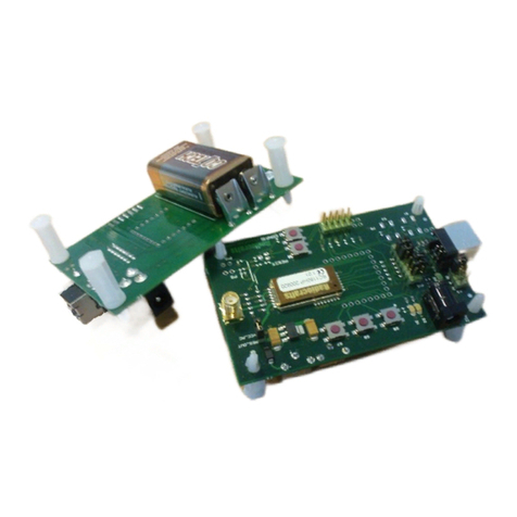
Figure 2. Sensor board(left) and development board(right)
Kit contents
Item
Number of articles
Sensor board w/RC1880-SPR module
2
Development board w/RC1880-GPR module
Antenna, 50quarter-wave monopole, SMA male connector
1
3
USB cable (micro)
3
This User Manual describes how to use the Development Kit and provides detailed documentation for the Sensor
board and Development board
The development board is connected to the gateway through USB. Your gateway may be an embedded
system or a Linux mini-computer. But for the purpose of demonstrating a quick setup, this guide will use a PC
as the gateway.

Page 5of 22
USER MANUAL RIIOT DEVELOPMENT KIT
2018 Radiocrafts AS
User Manual RIIoT Development Kit Rev. 1.00
Quick Start
When setting up the development kit, the main task is setting up the gateway. With the development kit the
quickest way to do this is to use a PC as the gateway and use the RIIoT Net Controller on Linux-PC or Linux
on a VirtualBox.
- Setup RIIoT Net Controller on the PC(gateway) RIIoT Net Controller Quick Start
- Start the example client application for the development kit. (details in above mentioned Quick start)
Once the RIIoT Net Controller is up and running, the Sensor boards can be powered up through USB and the
joining information and temperature/humidity readings will automatically start to appear on the gateway.
- Power up the 2 sensors board (demo application is pre-loaded out-of-box)
oApplication auto joins the network
oApplication read the on board SHT35 sensor and report humidity and temperature every 10
seconds.
oSee data being reported on the PC/gateway
The RIIoT network is now up and running.
Further development
Start making your own custom application
oRead a different sensor
oUse other channels or output power level
oAdd new timer events
oMake events based on button
oMake smart solution by adding intelligence processing on SPR module
oSend downlink messages from gateway to end node
oEvaluate range and different data rates.
The possibilities are infinite. Details for making your own application can be found in SPR SDK Quick Start,
User Manual and API reference.

Page 6of 22
USER MANUAL RIIOT DEVELOPMENT KIT
2018 Radiocrafts AS
User Manual RIIoT Development Kit Rev. 1.00
Development Board Introduction
The development board contains an USB connector, USB to serial converter, LEDs, voltage regulator, power
switch and programming/debug connector. All I/O signals are routed to holes at the edge suitable for 2.54 mm
pitch pin headers.
Figure 3: RC188x Development Board
Antenna connector
sub 1GHz
Module article
number
USB power LED
User LEDs
P1: USB micro
connector
RESET button
Power switch
PIFA PCB Antenna
2.4 GHz

Page 7of 22
USER MANUAL RIIOT DEVELOPMENT KIT
2018 Radiocrafts AS
User Manual RIIoT Development Kit Rev. 1.00
Block Diagram
RC1885DB only
JTAG/
cJTAG
USB to UA
RT
Regulator
3.3V / 50 mA
P3
SMA
P1
USB
Buttons:
RESET
P8: JTAG
Programming
Connector
USB
VBUS (5V/100mA)
USB
LEDs
RF
Sub
1G
Hz
3V3OUT
Radiocrafts
Module
UART
P4-P7: 4*10 pins I/O connection, pitch 2.54mm
I/O
LEDs
Power
on
switch
Figure 4. Block schematic RC188xDB
RF
2.4
GHz
PIFA
antenna

Page 8of 22
USER MANUAL RIIOT DEVELOPMENT KIT
2018 Radiocrafts AS
User Manual RIIoT Development Kit Rev. 1.00
I/O connection
All pins to the module are available through standard pin rows using a pitch distance of 100 mil (2.54 mm).
These pins are connected to 4 x 10 pins holes named P4 to P7. The table below gives an overview of the
edge connectors and their logical signals. Details on the RC188x pinning can be found in [7].
I/O connection
Connector
PIN
Signal
RC188x PIN
Note
P4
1
GND
2
RX/TX
25
Not used
3
RESET
26
4
DIO_1
30
5
DIO_2
31
6
DIO_3
32
7
DIO_4
33
8
DIO_5
34
9
DIO_6
35
10
DIO_7
36
P5
1
DIO_8
37
2
DIO_9
38
3
DIO_10
39
4
DIO_11
40
5
DIO_12
41
6
DIO_13
42
7
DIO_14
2
8
DIO_15
3
9
DIO_18
4
10
GND
P6
1
GND
2
DIO_19
5
TXD output (Connected to USB FTDI chip)
3
DIO_20
6
RXD input (Connected to USB FTDI chip)
4
VCC_EXTERN
27
Via EMI bead to RC1880
5
DIO_21
8
6
DIO_22
9
7
DIO_23
10
8
DIO_24
11
9
TMSC
12
10
TCKC
13
P7
1
DIO_16/TDO
14
2
DIO_17/TDI
15
3
DIO_25
16
4
DIO_26
17
5
DIO_27
18
6
DIO_28
19
Not connected for RC1885. Module pin 19-21 are RF port
for 2.4 GHz.
7
DIO_29
20
8
DIO_30
21
9
Not connected
10
GND

Page 9of 22
USER MANUAL RIIOT DEVELOPMENT KIT
2018 Radiocrafts AS
User Manual RIIoT Development Kit Rev. 1.00
Sensor Board Introduction
The Sensor Board includes the module to be evaluated. In addition it contains other circuitry needed for powering
and communication to the module. All I/O signals are routed to holes at the edge suitable for 2.54 mm pitch pin
headers for easy monitoring and control externally.
The board includes 6 different sensors and a controllable LED to demonstrate GPIO control options.
Sensor
Manufacturer
Sensor Type
SHT35
Sensirion
Precision Temperature and Humidity Sensor
HDC2010
Texas Instruments
Low Power Temperature and Humidity Sensor
BME680
Bosch Sensortech
Environmental sensor
ALS-PT-315C
Everlight
Analogue Light Sensor
SL353LT
Honeywell
Hall detector
LIS3DE
ST
Accelerometer
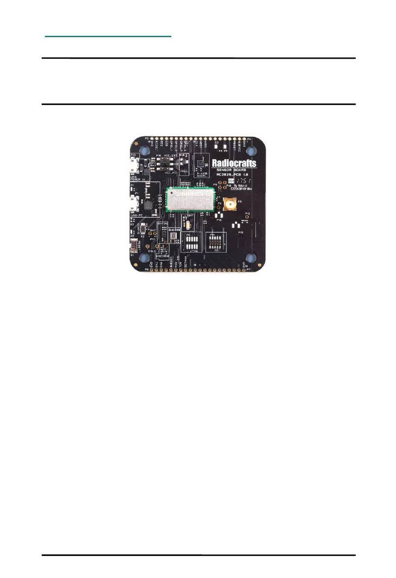
Figure 5: Sensor Board
Antenna connector
sub 1GHz
Radiocrafts
Module
Power LED
LED/GPIO
P1: USB TO PC
RESET
BUTTON
Connector holes
P4/P5
Connector holes
P6/P7
Power selection
PIFA PCB Antenna
2.4 GHz (not used)
P13: USB power

Page 10 of 22
USER MANUAL RIIOT DEVELOPMENT KIT
2018 Radiocrafts AS
User Manual RIIoT Development Kit Rev. 1.00
Block Diagram Sensor Board
USB to UA
RT
Regulator
3.3V / 50 mA
P3
SMA
P1
USB
Buttons:
RESET
P14 :Programming
Connector
USB
VBUS (5V/100mA)
POWER
LED
RF Sub
1GHz
3V3OUT
Radiocrafts
Module
UART
P4-P7: 4*10 pins I/O connection, pitch 2.54mm
I/O
LEDs
Power
Selector
Figure 6. Block schematic Sensor board
P1 USB
Power
LDO
HDC2010
SHT35
BME680
I2C
Light
sensor
ADC
LIS3DE
SPI
HALL
Sensor
I/O

Page 11 of 22
USER MANUAL RIIOT DEVELOPMENT KIT
2018 Radiocrafts AS
User Manual RIIoT Development Kit Rev. 1.00
Powering the Sensor Board
The sensor board can be power in several different ways, thus giving flexibility and ease of use.
Power source
Jumper position/RED
Comment
USB power 1A
VCC - VCC_EXT
Make sure to use a USB power source
capable of 1 A. A PC does normally not offer
that high current
Extern Volt 4-11 V
/9V battery
VCC - VCC_EXT
Connect through pin holes at edge. Here a
9V battery can also be connected.
NB: Using VCC > 6V, continuous
transmission test mode cannot be used.
Battery 3.0/3.6V
VCC - OFF/BAT
Battery can be connected
USB PC
VCC –VCC_PC
Only for RC1180MSM. The others draw too
high current
The sensor board is setup with a green power on LED, D1. This draws 2 mA and is always on. In case of
using the sensor board for battery operated proof of concept, this LED need to be removed to ensure low
power consumption
Controlling and Configuring Sensor Board
The sensor module can be controlled and configured through UART. For ease of use the UART is connected
through a UART-to-USB bridge from FTDI and to a micro USB contact.
By connecting a computer to this USB connector on the sensor board, a terminal emulator program can be
used to communication with the module. There is also a config button on the board to easily put the module in
configuration mode. See datasheets [6] and user manual for details on communication via UART.

Page 12 of 22
USER MANUAL RIIOT DEVELOPMENT KIT
2018 Radiocrafts AS
User Manual RIIoT Development Kit Rev. 1.00
I/O Connection
All pins to the module are available through standard pin rows using a pitch distance of 100 mils (2.54 mm).
These pins are connected to 4 x 10 pins holes named P4 to P7. The table below gives an overview of the
edge connectors and their logical signals. Details on the pinning can be found in module datasheet.
I/O connection
Connector
PIN
Signal
Module (Sensor
board)
Module
PIN
Note
P4
1
GND
2
VCC
Not used
3
RESET
4
Not used
Internally connected –Do not use
5
GPIO8
34
6
GPIO7
35
7
GPIO6
36
8
GPIO5
37
9
SPI_MISO
31
10
SPI_MOSI
32
P5
1
SPI_CLK
33
2
GPIO4
38
3
GPIO3 (SPI_CS)
39
4
GPIO2 (HALL_OUT)
40
5
GPIO1 (DRDY)
41
6
GPIO0 (LED_1)
42
7
CTS
2
8
RTS
3
9
VCC_4_11V
Not connected to module
10
GND
P6
1
GND
2
BSL
4
3
TXD
5
TXD output (Connected to USB FTDI
chip)
4
RXD
6
RXD input (Connected to USB FTDI
chip)
5
VCC
27
Via EMI bead to module
6
SDA
8
7
SCL
9
8
ADC0
(LIGHT_OUT_ANALOG)
10
9
ADC1
11
10
TMSC
12
JTAG programming interface. Do not
use.
P7
1
TCKC
13
2
TDO
14
3
TDI
15
4
SENS_1
16
Reserved for future use.
5
SENS_2
17
6
SENS_3
18
7
PA_CTR
19
8
PA_CTR
20
9
PA_CTR
21

Page 13 of 22
USER MANUAL RIIOT DEVELOPMENT KIT
2018 Radiocrafts AS
User Manual RIIoT Development Kit Rev. 1.00
I/O connection
Connector
PIN
Signal
Module (Sensor
board)
Module
PIN
Note
10
GND
I/O Silkscreen
On revision 1.0 of the sensor board there are some inaccuracies in the silkscreen print.
GPIO numbering is wrong and ADC1 marking is missing. Marking of RXD/TXD are offset.
See below
ADC1
ADC0
0
1
2

Page 14 of 22
USER MANUAL RIIOT DEVELOPMENT KIT
2018 Radiocrafts AS
User Manual RIIoT Development Kit Rev. 1.00
SHT35 Temperature and Humidity Sensor
SHT35 is the next generation of Sensirion’s temperature and humidity sensors. It has a typical accuracy of ±
1.5 %RH and ± 0.1 °C. It connected to sensor module by I2C and is setup with I2C address 0x44.
HDC2010 Low Power Temperature and Humidity Sensor
The HDC2010 is an integrated humidity and temperature sensor from Texas Instruments, with very low power
consumption and in an ultra-compact package. I has an accuracy of ± 2 %RH and ± 0.2 °C. It connected to
sensor module by I2C and is setup with I2C address 0x40.
The data ready pin is connected to the GPIO-2 of the sensor module.
BME680 Environmental sensor
BME680 is an integrated environmental sensor developed specifically for mobile applications and wearables
where size and low power consumption are key requirements. The sensor reads is a 4-in-1 sensor that
measure gas, humidity, pressure and temperature. It connected to sensor module by I2C and is setup with I2C
address 0x76.
ALS-PT-315C, Analogue Light Sensor
The ALS-PT-315C is light sensor that gives an analogue output based on the illuminance (Lux). The output is
connected to the analogue input of the sensor module. On the sensor board this sensor is always on.

Page 15 of 22
USER MANUAL RIIOT DEVELOPMENT KIT
2018 Radiocrafts AS
User Manual RIIoT Development Kit Rev. 1.00
SL353LT Hall Detector
The SL353LT is a state-of-the art hall detector that enable magnetic detection. It has a very low power
consumption of 1.8 uA in average for 2.8V operation. The output of the hall detector is connected to GPIO-3
on the sensor module.
LIS3DE Accelerometer
The LIS3DE is an ultra-low-power high-performance 3-axis linear accelerometer belonging to the “nano”
family, with digital I2C/SPI serial interface standard output. The device features ultra-low-power
operational modes that allow advanced power saving and smart embedded functions.
It is connected to the sensor module via the SPI and GPIO-4 is the chip select pin.
Blue LED
There is a blue LED on the board (D2) that is connected to GPIO-1 of the sensor module. This is used to
demonstrate the GPIO output control capabilities of the sensor module.

Page 16 of 22
USER MANUAL RIIOT DEVELOPMENT KIT
2018 Radiocrafts AS
User Manual RIIoT Development Kit Rev. 1.00
Prototyping with the Sensor Board
The sensor board is well suited for prototyping/bread boarding. With all I/O pins easily accessible at the edge,
connection to external boards can be made through board stacking with standard pin headers or cabled with
standard 2.54 mm pitch cable.
With angled header mounted on I/O connector, the sensor board can also be mounted vertically to other boards
with 2.54mm pitch connectors.
The idea is that an external application specific circuitry/sensors etc. easily can be connected to the sensor
board as a proof of concept for the final product.
The sensor board is built to fit a commercially off the shelf enclosure named Router Cube from New Age
Enclosure. Available at Mouser. The sensor board is not delivered with enclosure. Machining for
connectors/antenna is required.
Figure 7 Optional enclosure from New Age Enclosures

Page 17 of 22
USER MANUAL RIIOT DEVELOPMENT KIT
2018 Radiocrafts AS
User Manual RIIoT Development Kit Rev. 1.00
Sensor Board PCB and Assembly Layout
The PCB is a simple 4-layer board where Layer 2 is used as ground plane. The laminate used is standard FR-
4 board material. The PCB is 1.6mm thick. Full resolution layout and assembly drawing are found in [8].
Figure 8. Sensor Board PCB component placement, top side
Sensor Board Circuit Diagram
The circuit diagram of RC1xxx-xSM-SB is in figure 6. For better quality please see PDF in [8].

Page 18 of 22
USER MANUAL RIIOT DEVELOPMENT KIT
2018 Radiocrafts AS
User Manual RIIoT Development Kit Rev. 1.00
Figure 9: RC1xxx-xSM-SB Circuit diagram, page 1

Page 19 of 22
USER MANUAL RIIOT DEVELOPMENT KIT
2018 Radiocrafts AS
User Manual RIIoT Development Kit Rev. 1.00
Figure 10: RC1xxx-xSM-SB Circuit diagram, page 2

Page 20 of 22
USER MANUAL RIIOT DEVELOPMENT KIT
2018 Radiocrafts AS
User Manual RIIoT Development Kit Rev. 1.00
Sensor Board Bill of Materials
The circuit diagram includes all components of RC1xxx-xSM-SB, but the Bill of Material describes which
components are mounted. Details are listed in the following table. Components not mounted are marked DNM
(Do Not Mount) in the ‘Quantity/# column.
Bill of materials for Sensor board
Reference
Quantity
Part number
Description
L2-7
6
BLM18HE102SN1
EMI filter bead, 1000ohm@1GHz
U6
1
BME680
Environmental sensor
P14
1
CONN_2X5_SMT_1.27MM
Connector 2x5 SMT with 1.27 mm spacing
P8
DNM
CONN_2X5_SMT_1.27MM
Connector 2x5 SMT with 1.27 mm spacing
P1;P13
2
CONN_USB_MICRO_SMT
USB micro connector SMT
P4-7
DNM
CON_10_TH
Connector, 0.9mm pin
P11-12;P19
DNM
CON_1_TH
Connector, 0.9 mm pin
P18
1
CON_2X3_SMD
Connector, 2x3 pins, SMD, pitch 2.54mm
P9-10;P17
DNM
CON_2_TH
Connector, 0.9 mm pin
P2
DNM
CR2032_HOLDER
HOLDER for coin cell
C6-7;
C9;C25;C26
DNM
C_0402
Capacitor, 0402, general
C14-17;C19;
C21;C23-24
8
C_100N_0402_X5R_K_10
Capacitor, 0402
C3-5;C12-13
5
C_100N_0603_X7R_K_50
Capacitor, 0603
C22
1
C_10U_0402_X5R_K_6.3
Capacitor, 0402
C18
1
C_220U_1206_X5R_M_6.3
Capacitor, 1206
C8
DNM
C_1206
Capacitor, 1206
C1-2;C10-11
4
C_22U_0603_X5R_M_6.3
Capacitor, 0603
C20
DNM
C_VSCM_005R4_155A
EDLC capacitor, 1.5F, 5,4V
D4-5
2
D_SCHOTTKY_PMEG2010ER
Schottky diode, low Vf =.24V @ 200mA
U1
1
FT230XQ
FTDI USB to UART
U5
1
HALL_SL353LT
Hall sensor, low duty cycle, SOT23
U4
1
HDC2010
Temp and humidity sensor
U3
1
LDO_LP38690
Low drop regulator, 3.3V, 1 A, 3x3mm
WSON
D2
1
LED_BLUE_0603_2MA
LED 0603 Blue 2mA If
D1
1
LED_GREEN_0603_2MA
LED 0603 Green 2mA If
D3
DNM
LED_YELLOW_0603_2MA
LED 0603 Yellow 2mA If
U7
1
LIS3DE
3 axis accelerometer
S1
1
PUSH_BUTTON_RA
Push button, SMD, Right angled
S2
1
PUSH_BUTTON_SMALL_ELEVATED
Push button, SMD
S3
DNM
PUSH_BUTTON_SMALL_ELEVATED
Push button, SMD
M1
1
RF module, depend on variant of board
RC1682-SSM
RC1692HP-SSM
RC1180-MSM
RC1701HP-MSM
Sensor module
R3-5 ;R11-14
;R16;R18;R20;
R25-27; R32;
22
R_0402
Resistor, 0402, general
Table of contents
Other Radiocrafts Microcontroller manuals
Popular Microcontroller manuals by other brands

ARM
ARM KEIL Infineon XMC4500 Relax Lite Board quick start guide

mikroElektronika
mikroElektronika ROTARY R click quick start guide

NXP Semiconductors
NXP Semiconductors FRDM665SPIEVB user manual

ST
ST SPIRIT1 user manual

Espressif Systems
Espressif Systems ESP8266 SDK AT Instruction Set

Telit Wireless Solutions
Telit Wireless Solutions LM940 1.0 Design guide

D3
D3 DesignCore RVP-TDA4V Series quick start guide

Freescale Semiconductor
Freescale Semiconductor MPC5604B quick start

ST
ST STM32F401 Discovery user manual

Equinox Systems
Equinox Systems EPSILON5 MKII user guide

Texas Instruments
Texas Instruments LP-EM-CC1354P10-1 Hardware setup

Equinox Systems
Equinox Systems Flash 8051 Getting started