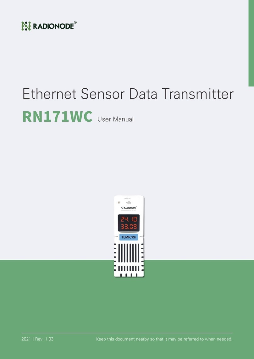
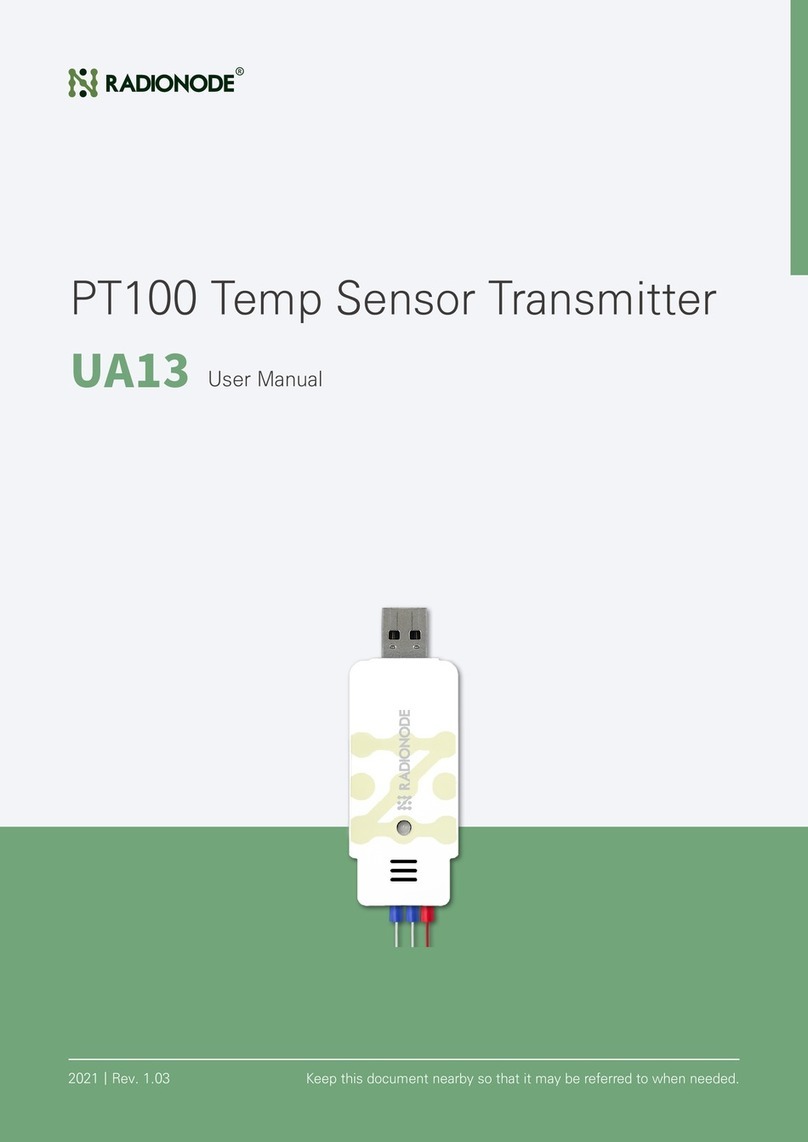
Radionode RN171 User manual

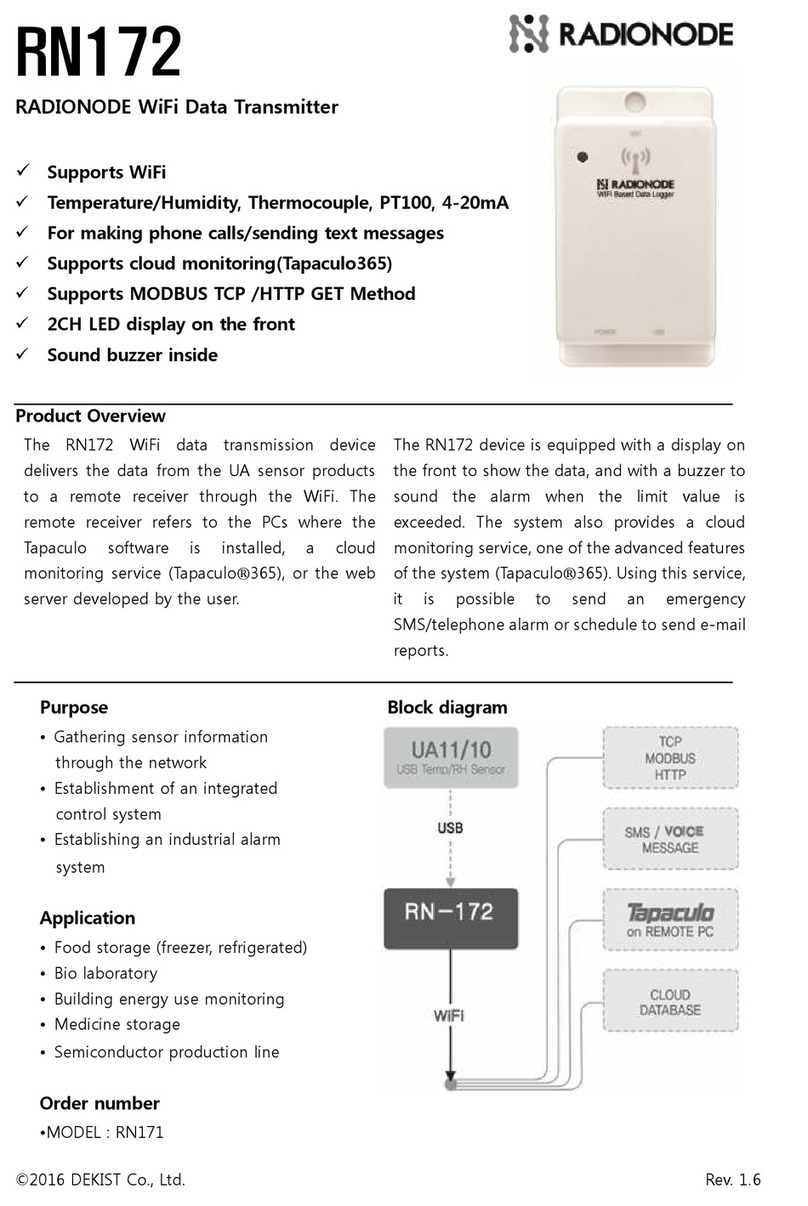
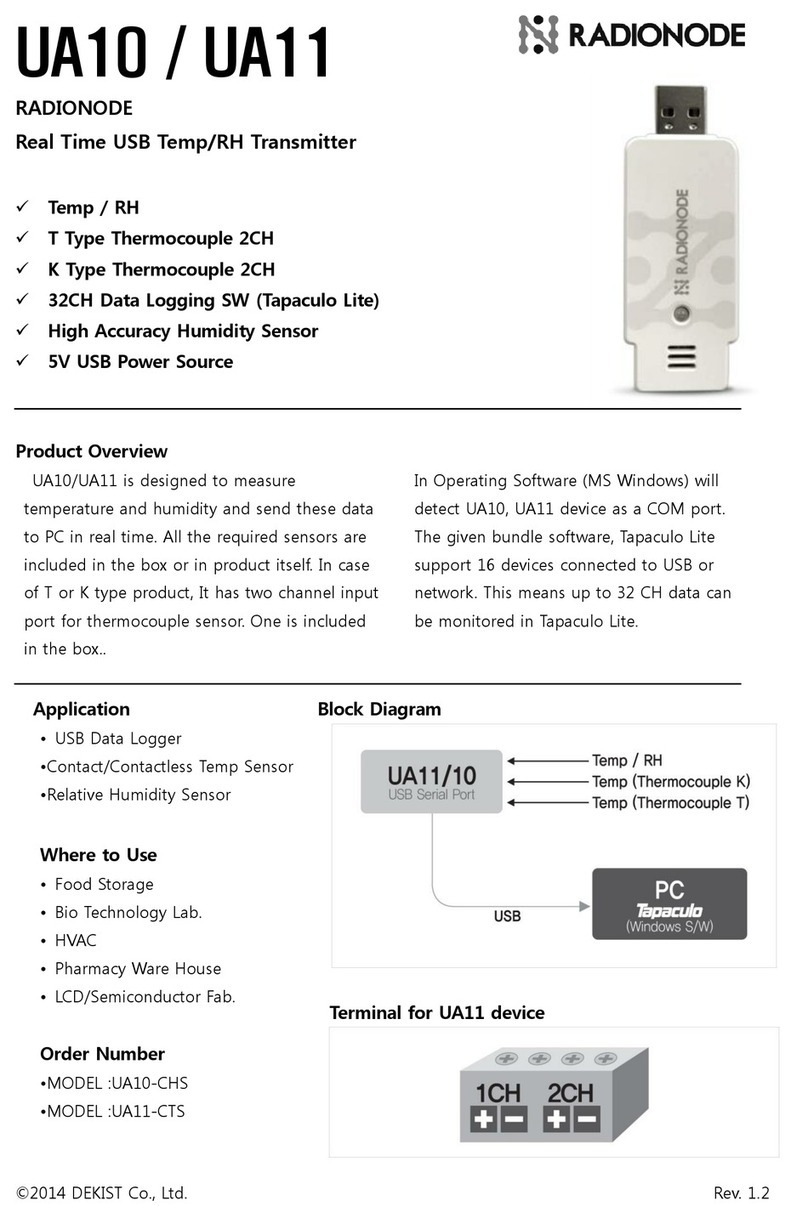
RN171
RADIONODE Sensor Data Transmitter Device
(via Ethernet)
✓POE(Power Over Ethernet)-supported
✓Temperature/Humidity, Thermocouple(T/K
Type), PT100, 4-20mA, Gas
✓For making phone calls alert/sending SMS
alert
✓Supports cloud monitoring(Tapaculo365)
✓Supports MODBUS TCP/HTTP data
transmission
✓2CH LED display on the front
✓Sound buzzer inside
Product Overview
The RN171 Ethernet data transmission device delivers
the data from the UA sensor products to a remote
receiver through the Ethernet.
The remote receiver refers to the PCs where the
Tapaculo software is installed, a cloud monitoring
service (Tapaculo®365), or the web server developed
by the user.
The RN171 device is equipped with a display
on the front to show the data, and with a buzzer
to sound the alarm when the limit value is
exceeded.
The system also provides a cloud monitoring
service, which is one of the advanced features
of the system (Tapaculo®365).
Using this service, it is possible to send an
emergency SMS/telephone alarm or schedule
to send e-mail reports.
Purpose
• Gathering sensor information
through the network
• Establishment of an integrated
control system
• Establishing an industrial alarm
system
Application
•Food storage (freezer, refrigerated)
• Bio laboratory
• Building energy use monitoring
• Medicine storage
• Semiconductor production line
©2019 DEKIST Co., Ltd. www.radionode365.com Rev. 1.9

Order number Block diagram
• Model : RN171
1.Specification
RN171 Product Specifications
Size
H25 * W50 * D70 (mm)
Communication
protocol
Ethernet 100Mbps
Power
consumption
POE 48V, IEEE802.3af/at,
DC6V, 1.9W
HTTP
transmission protocol
RADIONODE PROTOCOL
HTTP GET
Buzzer
Threshold alarm
MODBUS TCP
PORT 502 ,
HOLDING REGISTER
FUNCTIONCODE 03,
CH1,CH2 Data
LED
Two color(red/green LED)
SMS transmission
Supported,
TAPACULO365.COM
USB Port
For connecting to the PC for
setting or connecting with the
UA series product
Making phone calls
Supported,
TAPACULO365.COM
Compatible
USB sensors
RADIONODE UA series
Cloud monitoring
S2.TAPACULO365.COM
LOGIN
Display
LED display on the front for
displaying Data or IP Addr.
Data transmission
frequency
Can be configured every
minute (minimum)
Mounting
Direct attachment through
bolts
Telnet/
Broadcasting
TCP Port 23
UDP Port 50000 (device
detection)
©2019 DEKIST Co., Ltd. www.radionode365.com Rev. 1.9

2. Components
Model
Components
RN171-W
RN171W(1EA), USB Extension Cable(1EA), USB gender(1EA)
3. Products Caution
Warning
1. In case of use on a device that impacts human life or property, be sure to attach a safety device in
double. It can result in serious loss such as fire, personal injury or property damage.
2. This product is not an explosion[proof structure and should not be used for flammable gas.
There is a risk of explosion.
Caution
1. Avoid excessive environmental exposure and do not use it outside the supported operating
environment.
It may shorten the life span of the product and cause malfunction
2. Do not use it to exceed the power voltage range.
Otherwise, the product may be damaged.
3. Do not short-circuit the load.
Otherwise, the product may be damaged.
4. Do not miswire the power, such as polarity.
Otherwise, the product may be damaged.
5. Do not twist or apply force to the case of this product.
Otherwise, the product may be damaged.
©2019 DEKIST Co., Ltd. www.radionode365.com Rev. 1.9

4.How to Operate
Connecting to the POE
Connecting with the USB sensor
4.1 Data logging on the local PC
RN171 is a suitable product for establishing an integrated monitoring server through the Ethernet. It
is used to transmit the data gathered by UA 10 or UA11, etc. The image above shows an example of
a configuration of the monitoring server through the intranet, without being connected to the internet.
It is possible to be assigned an IP automatically or to have a fixed IP manually assigned by the user.
The Tapaculo Lite software provided as a part of the package is used to detect a device and make
©2019 DEKIST Co., Ltd. www.radionode365.com Rev. 1.9

requests for the data to the device. The data received from the device is saved in the DB. <See 11.
How to use the Tapaculo Lite PC bundle software>
4.2 Data logging in a remote location
Through the internet, it is possible to use the product to gather information from other devices
located in a remote place. Each RN171 device will do with a private IP from the internet router. No
separate public IP is necessary. Tapaculo365.com supports data gathering. It provides free accounts
with which you can use up to 20 data channels. The registration of the device is completed by
inputting the MAC address indicated on the side of the RN171 unit. <See 10. How to use the
Tapaculo365.com web service>
©2019 DEKIST Co., Ltd. www.radionode365.com Rev. 1.9

5. Console Menu
Using the USB cable, you can access the configuration menu through the PC. While the POE is not powered
on, use the USB cable to connect the RN171 unit to a PC. When power is supplied through the USB cable,
the device automatically operates in the reconfiguration console mode. Then, you can see a new COM port
created on the PC.
Also, you can use a Telnet terminal to access the same console menu. As the system is set to the DHCP
mode by default, you can view the IP address on the LED display when the system is powered up. When you
establish a connection with Telnet, enter the “ATSCON”command to jump to the console menu screen. If
there is no input made for five minutes, the connection will automatically be disengaged.
Use the terminal software to access the COM port or use Telnet to input “radionode114.”Then, you can
access the configuration console menu as shown here. When using the radionode terminals, the COM ports
will be searched for automatically. When it is connected to a COM port, the background will turn green.
©2019 DEKIST Co., Ltd. www.radionode365.com Rev. 1.9

-----------------------------------------
RADIONODE RN171 SERIES SYSTEM INFORMAION
PRODUCT MODEL : RN171W
HTTP INTERVAL : 5 Min.
DATA DESTINATION : TAPACULO365.COM
ETHERNET MAC : D880393E05ED
VIRTUAL MAC : D880393E05ED
CURRENT IP ADDR : 0.0.0.0
MODBUS TCP PORT : 502
BUILD VERSION : Mar 31 2016
NVM PARAM SIZE : 912
HTTP BACKUP DB : 36040, Stored Samples(0)
-----------------------------------------
[Radionode RN170 Config Information.]
1.Network Setup.
2.System Setup.
3.Buzzer/Siren Setup.
4.HTTP Destination Setup.
5.MODBUS TCP Setup.
9.Quit(Back to normal Operation)
5.1 Network setting
[1.NETWORK SETUP MENU.]
A.Set DHCP [OFF]
B.Set IP Address [ 000.000.000.000 ]
C.Set GATEWAY Address [192.168.137.002 ]
D.Set DNS1 Address [192.168.137.002 ]
E.Set DNS2 Address [000.000.000.000 ]
F.Set SUBNET MASK [255.255.255.000]
G.Set VMAC [D880393E05ED]
H.Set UDP Broadcasting Port [50000]
I.Set TELNET Port [23]
Q.Quit.
A. Set DHCP ON/OFF. If you are to use a fixed IP, set it OFF, and if using a router, set it ON.
B. If you are using a fixed IP, input the IP address manually.
If the DHCP mode is OFF, this menu will not appear.
C. Input the gateway IP address manually.
D. Input the address of the DNS1 server.
E. Input the address of the DNS2 server.
F. Input the subnet mask value.
G. The VMAC has the same value as the MAC of the Ethernet. This is mainly used as a unique ID
value. Even when you change the VMAC value, the actual MAC value will not change.
H. Change the port that is used for UDP broadcasting.
I. Change the access port number on Telnet.
J. Change the port number used by the MODBUS TCP.
©2019 DEKIST Co., Ltd. www.radionode365.com Rev. 1.9

5.2 System configuration
[2.SYSTEM SETUP MENU.]
A.Set Device Name [ DEVICE-d880393e05ed]
B.Set Destination of HTTP[ TAPACULO365 ]
C.Set HTTP Update Interval [ 5 Min.]
G.Set FND Display Mode [ CH1&CH2 ON ]
H.Set Debug Print [ OFF ]
Q.Quit.
A. Change the name of the device. The default value is "Device-MAC address."
B. Select the transmission protocol for the data gathered. You can choose from TAPACULO365 and
CUSTOMER SERVER. Use the Customer Server setting in case the server has been developed
by the user.
C. Select the data transmission frequency. It can be configured every minute (minimum).
D. Choose whether to use the LED display on the front or not to. Both CH1/CH2 can be set ON or
OFF.
5.3 Channel alarm setting
[3.BUZZER&SIREN SETUP MENU.]
A.Set Alarm Trigger Mode [ CH1 OR CH2 ]
B.Set Alarm CH1 Min [ 0.00 ]
C.Set Alarm CH1 Max [ 0.00 ]
D.Set Alarm CH2 Min [ 0.00 ]
E.Set Alarm CH2 Max [ 0.00 ]
F.Set BUZZER Alert Enable [ SOUND ON ]
G.Set Remote SIREN DEVICE Enable [ OFF ]
(QLIGHT MODEL:ST56EL-ETNS-2-WS)
H.Set Remote SIREN DEVICE IP [ 192.168.1.111]
I.Set Remote SIREN DEVICE Port [ 2000 ]
Q.Quit.
A. Select the channel to use the alarm. The available channels are NOALRAM, CH1, CH2, CH1 AND
CH2, and CH1 OR CH2.
B. Input the Min value of Channel 1.
C. Input the Max value of Channel 1.
D. Input the Min value of Channel 2.
E. Input the Max value of Channel 2.
F. Choose whether to use the internal buzzer in the RN171 or not to (SOUND ON/OFF).
G. Turn the remote alarm lamps (siren) ON/OFF.
The alarm lamp model supported is ST56EL-ETNS-2-WS by QLIGHT CO. LTD.
H. Input the IP of the remote alarm lamp.
I. Input the port of the remote alarm lamp.
©2019 DEKIST Co., Ltd. www.radionode365.com Rev. 1.9
5.4 HTTP Request setting
[4.HTTP DESTINATION SETUP MENU.]
A.Set HTTP Host URL [ 100.10.10.112 ]
B.Set HTTP Host Port [ 80 ]
C.Set HTTP NMAC [ 0000D880393E05ED ]
D.Set HTTP DATAIN File[/test.jsp]
Q.Quit.
A. Input the URL of the server that receives the information through the HTTP protocol.
B. Input the port number of the server.
C. Input the NMAC to be transmitted to the data server. For an NMAC, add "0000" before the VMAC.
D. Input the name of the page to which the data is to be sent through the GET method. Submit a GET
request to the host on the HTTP protocol. The parameters of the GET request should include the
data values, device IP addresses, and more. For more details, see <8. Definition of the HTTP
protocol>.
5.5 MODBUS TCP setting
From the PLC or the PCs, etc., you may use MODBUS TCP to access the RN172, to find out the
values of CH1 and CH2 inside.
[5.MODBUS TCP SETUP MENU.]
--------------------------------------------------------------
HOLDING REGISTER (16BIT),FUNCTION CODE 3
--------------------------------------------------------------
OFFSET [0] : CH1 FLOATING 32BIT VALUE (16BIT LOW)
OFFSET [1] : CH1 FLOATING 32BIT VALUE (16BIT HIGH)
--------------------------------------------------------------
OFFSET [2] : CH2 FLOATING 32BIT VALUE (16BIT LOW)
OFFSET [3] : CH2 FLOATING 32BIT VALUE (16BIT HIGH)
--------------------------------------------------------------
OFFSET [4] : CH1 INTEGER 16BIT VALUE (16BIT)
--------------------------------------------------------------
OFFSET [5] : CH2 INTEGER 16BIT VALUE (16BIT)
--------------------------------------------------------------
A.Set MODBUS TCP PORT[ 502 ]
B.SetByteReverse [ 0] (1:Reversed,0:None)
Q.Quit.
A. Change the port number used by MODBUS TCP. Normally, the port number is set to 502.
B. Turn Byte Reverse ON/OFF. Select On(1) to change the sequence of the byte.
6. Display
©2019 DEKIST Co., Ltd. www.radionode365.com Rev. 1.9
An RN171 device is equipped with three indicative devices (LED, CH1 DISPLAY, and CH2 DISPLAY). LED
may operate in two colors. In most cases, you will see a green light, which means that the equipment is
functioning normally. When data is transmitted or an alarm is sounded, the lamp will turn red. The CH1/CH2
DISPLAY normally indicates the data value. In the case of the temperature, 29.40 means a 29.40℃
temperature. When the IP is automatically assigned when the device is powered up, it buzzes three times to
inform the user of the current IP address, and the screen will show the last two digits of the IP address.
Normally, an internet router assigns 192.168.0.1 as the IP address, with the last digit varying.
Expression of the data
Expression of the IP address
USB sensor
Most of the data show the current
value.
The example below shows that
the temperature is 19.2℃ and the
humidity is 42.1%.
When the device is powered up
and an IP is assigned
automatically,
the buzzer will sound three times,
showing a part of the IP address
while doing so. If the IP address
is 192.168.0.42, the screen would
look like this:
Appears when the USB sensor
product(UA Series) is not
connected.
19.20
42.10
-000
-042
----
----
Automatic data backup
Automatic data recovery
USB connection (change with
©2019 DEKIST Co., Ltd. www.radionode365.com Rev. 1.9
the detailed settings)
Appears when the data could not
be sent to Tapaculo365.
The numbers below show the
number of samples saved in the
internal memory.
Appears when the data in storage
is retransmitted to Tapaculo365.
Appears when the device is
connected to the PC through the
USB without a separate power
supply. This mode is used to
change the settings.
HoLd
0005
0000
CONF
7. Telnet(command)
While the RN171 device is in operation, the user may access the device through Telnet. After accessing the
©2019 DEKIST Co., Ltd. www.radionode365.com Rev. 1.9
device through Telnet, input the AT command to view or change the settings of the RN171 device. The
default port number is 23.
AT Command
Contents
Answer
DATA
ATDC
Checks the current CH1 and CH2
values.
“ATDC 29.11,
22.11”
S
Y
S
T
E
M
ATSQUIT
Disengages the current connection.
[disconnection]
ATSCON
Enters the console mode. It works the
same way as the USB console
reconfiguration.
[CONSOLE MODE]
ATSRESET
Resets the RN171.
[RESET]
ATSMODEL
Shows the model name of the RN171
product.
“ATSMODEL
RN171-W”
B
U
Z
Z
E
R
ATBSET
Temporarily activates the internal
buzzer of the RN171.
“OK”
ATBAL +
[“OFF”,”CH1”,”CH2”,
“OR”,“AND”]
Chooses the alarm condition.
OFF: Do not use the alarm.
CH1: Alarm activated on Channel 1.
CH2: Alarm activated on Channel 2.
OR: Alarm activated on CH1 or CH2
AND: Alarm activated on CH1 and
CH2
“OK” or “NOT_OK”
ATBMIN1 + [Value]
Input the Min value of Channel 1.
“OK” or “NOT_OK”
ATBMAX1 + [Value]
Input the Max value of Channel 1.
“OK” or “NOT_OK”
ATBMIN2 + [Value]
Input the Min value of Channel 2.
“OK” or “NOT_OK”
ATBMAX2 + [Value]
Input the Max value of Channel 2.
“OK” or “NOT_OK”
OTHER
s
OTHERs
Meaningless command
“NOT_OK”
8. Definition of the HTTP protocol
©2019 DEKIST Co., Ltd. www.radionode365.com Rev. 1.9
RN171 defines and uses the RADIONODE HTTP. It sends HTTP GET requests to the server at regular
intervals. When a request has been made, the data needed as the parameters are sent together.
Rather than using the PULL method, where the server reads in the data, we are using the Push method,
where the data is pushed up to the server, which web developers are more familiar with.
8.1 DATAIN(Data transmission)
A.HTTP Request
http://[SERVER-ADDRESS]/[DATAIN-FILE]
?gwid=0004a316d728&model=RN171&interval=300&ipaddr=192.168.0.31&utc=1459249
259
__device=00000004a316d728&nodeid=00000004a316d728&lqi=255&child=0&nodetype=
2&batt=255&sd1=20.28&sd2=20.29
gwid : Uses the MAC address as the unique ID of the RN171 unit.
The VMAC information is used.
model : The model number of RN-171 (RN171).
interval : The frequency of sending the HTTP signals applicable to RN-171 (seconds).
ipaddr : The IP address currently used by RN-171.
utc : The Unix Timestamp from the default NTP of RN171.
If the RN171 device fails to establish a connection with an external NTP server,
it willprovide incorrect time information. This device connects to pool.ntp.org /
tapaculo365.com to retrieve the time information.
__device : Uses the MAC address as the unique ID of the node from which the
information has been transmitted. The NMAC information is used.
nodeid : The same value as __device is used..
lqi : Shows the wireless signal strength, ranging from 0 to 255.
For RN171, the value is always “255."
child : Shows the number of the child node under the current node.
For RN171, the value is always "0."
nodetype : Defines the type of node. For RN171, the value is always “2."
batt : Shows the battery status of the node. For RN171, the value is always “255."
sd(x) : x means the sequence and means the value of the sensor. The value is shown
up to two decimal digits. Negative values are allowed.
sd1: The data value of Channel 1
sd2: the data value of Channel 2 (temperature and humidity, etc.)
©2019 DEKIST Co., Ltd. www.radionode365.com Rev. 1.9

B. HTTP Response
Normal response
Abnormal response
A normal response will always be ignored.
An abnormal response will always be
ignored.
9. MODBUS TCP Protocol Definition
It is possible to read the currently measured data from RN171 through MODBUS TCP communication. The
data is updated to “HOLDING REGISTER”in real time. The 4 BYTE FLOATING POINT and 2 BYTE
UNSIGNED INT formats are supported. Reading is possible. In the case of 2 BYTE UNSIGNED INT, the
decimal digits are ignored, and only the integers are delivered.
Transaction ID, Protocol ID, and Unit ID are internally ignored. Whatever value you input through them, they
will use 3 as the function code.
READ HOLDING REGISTER, FUNCTION CODE: 3
Channel
Address Index
16Bit
16Bit
(Byte Reverse)
Value
CH1
4 Byte Floating
0
0x3333
0x3333
27.9
1
0x41df
0xdf41
CH2
4 Byte Floating
2
0x999a
0x9a99
29.2
3
0x41e9
0xe941
CH1
2Byte Unsigned INT
4
0x001b
0x1b00
27
CH2
2Byte Unsigned INT
5
0x001d
0x1d00
29
[The byte sequence of the register map inside RN171, and the data bytes]
10. How to Use the Tapaculo365.com Web Service
©2019 DEKIST Co., Ltd. www.radionode365.com Rev. 1.9

If the RN171/172 products can be connected to the internet, the field data can be monitored from a remote
place with ease.
10.1 Installation of the device
Connect the RN171/172 devices to the power source and proceed with the establishment of an internet
connection. You may use either a router or a fixed IP. If the LED lamp on the front blinks in red and green
alternately, the internet connection has been established. If only the green light is on and you don't hear
the melody, there is something wrong with the internet connection.
How to check the status during installation
● Unregistered device : The LED on the front blinks in red and green alternately
once the power is on.
● Registered device: When the power is on, you will hear the melody.
● When there is an error with the internet connection: There is no reaction when
you connect the power. Only the green light will remain on.
10.2 Registering a new device
Access S2.TAPACULO365.COM.
If you are not yet a member, sign up for membership first.
Once you are logged in, go to Device Configuration > New Device. A device that is connected to the
internet will automatically be detected. Basically, it detects the devices that are using the same IP band.
When searching for a device located at places other than those covered by the same network, search
based on the ID of the device (MAC address).
©2019 DEKIST Co., Ltd. www.radionode365.com Rev. 1.9

Press the Add a Device button to open a pop-up window. Then input the descriptive text on the device.
Then press Save to complete the addition of the device. The device will play a melody to indicate that the
registration process has been completed.
10.3 Add a new channel
Once a new device is added, add a data that transmits the actual data. Move to the New Channel menu.
You will find the data channel that is generated by the newly added device detected. If the new channel is
not detected, wait until the next data update or reboot the device so that the channel can be detected.
©2019 DEKIST Co., Ltd. www.radionode365.com Rev. 1.9

Click the Add Channel button. A pop-up window will appear. Input the channel name and select the unit to
complete the registration.
Once the channel name is registered, make proper preparations so that the report, dashboard, or detail
view screen will show the relevant name.
10.4 Use the web service
After completing the channel registration, you may use the various features, such as the report,
dashboard, or alarm setting, of S2.Tapaculo365.com. All the customers who purchased this product may
use these features basically free of charge. If you require advanced features, you may switch to the paid
services.
Ex) Dashboard
©2019 DEKIST Co., Ltd. www.radionode365.com Rev. 1.9

Ex) Reports
11. How to Use the Tapaculo Lite PC Bundle Software
11.1 Install Tapaculo Lite in your PC
Install Tapaculo Lite(www.radionode365.com > Support > Software Download > Tapaculo Lite) on a
Windows-operated PC and launch the program.
Click "Create Project" to create a new project and add the devices.
©2019 DEKIST Co., Ltd. www.radionode365.com Rev. 1.9

11.2 Add a new device to Tapaculo Lite
Access the Create Project menu, and you will see the RN171 devices detected as Broadcasting. Of
these, select the device whose data you wish to save. Select the time interval for saving the data from
among 1 sec, 5 secs, 10 secs, 1 minute, 5 minutes, and 10 minutes. Choose carefully as you cannot
change these settings once the project is created.
If the broadcasting port is blocked by a firewall, the device will not be detected automatically. In this case,
push Manual Add to manually register the device. The system is configured to use the UDP 5000 port for
detecting through Broadcasting, and the TCP 23 port for gathering data.
12. Certification
▷ FCC Class A digital device
NOTE: This equipment has been tested and found to comply with the limits for a Class A digital device, pursuant to part
15 of the FCC Rules.
These limits are designed to pro-vide reasonable protection against harmful interference when the equipment is
operated in a commercial environment.
This equipment generates, uses, and can radiate radio frequency energy and, if not installed and used in accordance
with the instruction manual,
may cause harmful interference to radio communications. Operation of this equipment in a residential area is likely
to cause harmful interference in which case the user will be required to correct the interference at his own expense.
CAUTION: Changes or modifications not expressly approved by the manufacturer responsible for compliance could void the
user’s authority to operate the equipment.
▷ KCC 인증
A급 기기 (업무용 방송통신기자재)
이 기기는 업무용 (A급)전자파적합기기로서 판매자 또는 사용자는 이점을 주의하시기 바라며,가정 외의
지역에서 사용하는 것을 목적으로 합니다.
©2019 DEKIST Co., Ltd. www.radionode365.com Rev. 1.9

13. Question and Service
● Free repair service within one year.
● Paid repair service after one year.
● Company : DEKIST Co., Ltd
● Phone : 070-7529-4359
● Fax : 031-8039-4400
● Email : [email protected]
14. Software Download
You can download the relevant software at www.radionode365.com.
©2019 DEKIST Co., Ltd. www.radionode365.com Rev. 1.9
Table of contents
Other Radionode Transmitter manuals